1
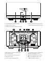
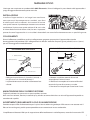
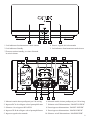
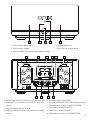
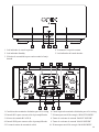
INTEGRATED AMPLIFIER
AMPLIFICATORE INTEGRATO
AMPLIFICATEUR INTÉGRÉ
VOLLVERSTÄRKER
AMPLIFICADOR INTEGRADO
Mod. OA - 102
E
ID
S GU
R'
USE
SO
’U
LE D
NUA
MA
R
U
ATE
ILIS
L'UT
E
D
DE
GUI
RC
SPE
A
R IG
KER
A
HT
X LR
IR I
R
ON
PO
/ S TA
WE
ND
M
R A
P L IF
BO
A
BY
IE R
OA
G
TUN
102
EI
BED
UN
IEN
NL
GSA
A
GUÍ
WE
R
US
B
O
ARI
U
S
LU
DE
O
PO
ST
EO
INDEX
ENGLISH.......................3-23
ITALIANO...........................7
FRANÇAIS........................11
DEUTSCH.........................15
ESPAÑOL.........................20
USER'S GUIDE
Thank you for purchasing ONIX Electronics. With sincere appreciation, we suggest that you should read this User’s
Manual thoroughly before operation and keep the Manual properly for further reference.
INSTALLATION
I n s t a l l t h e u n i t i n a we l l ve nt i l ate d p l a ce a n d n o t
exposed to high temperatures or humidity, nor any heat
sources such as heaters or radiators. Be sure to leave
space around the unit for ventilation to improve heat
radiation (at least 30 cm at top, 10 cm at rear, and 20 cm
at each side). If not enough space is provided between the
unit and walls or other equipment, heat will build up inside, interfering with performance or causing malfunctions.
CONNECTIONS
Before making or changing the connections, switch off the power switch to prevent damaging the product.
To connect the speakers, always check the correct polarity (red +) (black -) to avoid damaging them irreparably.
CONNECTING THE PIN-RCA CORDS
CONNECTING THE SPEAKER CORDS
10mm
1.
1 Left channel
L
3 White plug
Twist the wire core.
3.
2.
2 Right channel
R
1
2
4 Red plug
Connect the white plug 3 to the L (left) channel 1,
1. Strip off the vinyl covering and twist the tip of
and the red plug 4 to the R (right) channel 2.
the wire core.
Be sure to push the plugs securely.
2. Loosen the knob and insert the wire core into
the terminal hole.
3. Tighten the knob to fix the wire core in place.
MAINTENANCE OF EXTERNAL SURFACES
Remove dust and dirt with a clean, dry cloth.
Never use solvents, gasoline, insecticide sprays and other chemicals on or near the equipment because they can
corrode the surfaces.
POWER-CORD CAUTION
Handle the power cord by the plug. Do not pull out the plug by tugging the cord and never touch the power cord
when your hands are wet as this could cause a short circuit or electric shock.
The amplifier is equipped with filters for the suppression of radio interference in accordance with EEC regulation
3
ON / STANDBY
POWER AMPLIFIER
OA1 02
1. Left channel status indicator lamp
4. Remote control receiving window
2. Standby indicator lamp
5. Right channel status indicator lamp
3. Standby touch switch (whole metal strip)
SPEAKER RIGHT
SPEAKER LEFT
RCA
XLR
A
A
IR IN
R
L
MAIN POWER
BOOST POWER
B
B
USE ONLY WITH A 250V FUSE
USE ONLY WITH A 250V FUSE
FUSE
100V - 120V: T10AL
220V - 240V: T6.3AL
MODEL: OA102
POWER CONSUMPTION: <1200W
POWER AMPLIFIER
~ 2 2 0 V 5 0/ H z
SERIAL NO.:
1. Right channel sound box binding post
6. Left channel sound box binding post
2. RCA audio-in port
7.
BOOST POWER
switch
3. RCA/XLR audio-in selector switch
8.
BOOST POWER
4. XLR audio-in port
9.
MAIN POWER
input socket
10.
MAIN POWER
switch
5. Remote control signal input port
input socket
4
Listening
1 The amplifier can only work combined with his pre-amplifier OP 101, otherwise the amplifier can
be damaged beyond repair, and therefore damage the speakers also connected to it.
2. Set the VOLUME control of the pre amplifier OP 101 on the minimum and press the power switch (POWER).
3. Set the INPUT SELECTOR(of the preamplifier) on the source desired to play.
4. By means of the knob(of the preamplifier) you can select the desired playback source.
Inputs
Select the audio input from the preamplifier.
Protection
The device has a sophisticated protection circuit against the short circuits, distinguishing itself with the
simultaneous flashing of all LEDs for a few seconds, in this case must be unplugged the power cord and leave
unplugged for at least 15 minutes.
Troubleshooting
Incorrect operations are often mistaken for trouble and malfunctions. If you think that there is something wrong
with this component, check the points below. Sometimes the trouble may lie in another component. Investigate
the other components and electrical appliances being used.
If the trouble cannot be rectified even after exercising the checks listed below, ask your nearest ONIX authorized
service center or your dealer to carry out repair work.
Symptom
No power
supplied to unit
No sound
No sound from
one speaker
Cause
Power plug is disconnected from outlet
Remedy
Check that power cord and insert the plug
securely into outlet
The connection cables are connected
incorrectly to the speakers.
Check if connections between preamplifier
and the final amplifier are connected correctly.
The position of the input selector of
the preamplifier does not correspond
to the component to be played back.
Check if the LED of the input selector of the
preamplifier corresponds to the input source
that you want to listen.
Connecting cords or speaker cords
are disconnected on the side.
Verify that the cables between amplifier and
speaker are well- connected according to the
different polarity.
Components:
8 pairs of “BIG POWER” Sanken 2SC3264/2SA1295 transistors for each channel, filter capacitors: 4 10.000uF/160V
Nichicon “Super Through” capacitors “; 4 x MUR 8100 Ultra fast rectifier diodes, 2 “Silicon Steel” R-CORE
transformers weighing each 6.5 kg with a power of 1200W; Two stage power supply: MAIN POWER, that delivers
high power fast. The “BOOSTER POWER”, power stage is inserted to compensate for the additional power
demand, thus maintaining stability and low distortion.
5
XLR
RCA
Specifications
FREQUENCY RESPONSE
5Hz-50KHz (-0,5) dB
INPUT SENSIBILITY
430mV/47Kohm
SIGNAL/NOISE RATIO
100dB (A weighted)
CHANNEL SEPARATION
> 90dB
THD
0,005% (3W/8Ohm)
FREQUENCY RESPONSE
3Hz-55KHz (-1) dB
INPUT SENSIBILITY
830mV/47Kohm
SIGNAL/NOISE RATIO
105dB (A weighted)
CHANNEL SEPARATION
> 94dB
THD
0,0002% (3W/8Ohm)
OUTPUT POWER
2 x 300W RMS (8 Ohm) - 2 x 600W RMS (4 Ohm)
DIMENSION
L 480 x P 610 x A 270 mm.
WEIGHT
60 Kg.
POWER CONSUMPTION
1200 W
STANDBY CONSUMPTION
POWER SUPPLY
<1 watt
220V - 240V AC
Every specification and design of the product is subject to change without prior notice
Warranty
For warranty information, please contact your local ONIX distributor. Your purchase receipt is your permanent record
of a valuable purchase. It should be kept in a safe place to be referred to as necessary for insurance purposes or when
corresponding with ONIX. When seeking warranty service, it is responsibility of the consumer to establish proof and
date of purchase. Your purchase receipt or invoice is adequate for such proof.
IMPORTANT
CAUTION
RISK OF ELECTRIC SHOCK
DO NOT OPEN
The lightning flash with arrowhead symbol,
within an equilateral triangle, is intended to alert
the user to the presence of uninsulated
"dangerous voltage" within the product's
enclosure that may be of sufficient magnitude
to constitute a risk of electric shock to persons.
CAUTION:
TO PREVENT THE RISK OF ELECTRIC SHOCK, DO
NOT REMOVE COVER (OR BACK).
NO USER-SERVICEABLE PARTS INSIDE. REFER
SERVICING TO QUALIFIED SERVICE PERSONNEL.
The exclamation point within an equilateral
triangle is intended to alert the user to the
presence of important operating and
maintenance (servicing) instructions in the
literature accompanying the appliance.
This product complies with the Low Voltage Directive
(73/23/EEC), EMC Directives (89/336/EEC, 92/31/EEC) and CE
Marking Directive (93/68/EEC).
6
MANUALE D’USO
Grazie per aver acquistato un prodotto della ONIX Electronics. Prima di collegare la presa elettrica del apparecchio si
prega di leggere attentamente questo manuale.
INSTALLAZIONE
Installare l’apparecchio in un luogo ben ventilato e
non esposto ad alte temperature o umidità, ne a fonti
di calore quali stufe o radiatori. Assicuratevi di lasciare
uno spazio intorno al prodotto per ottenere una corretta
ventilazione (lasciate uno spazio minimo di 30 cm in alto,
di 10 cm dietro l’unità e di 20 cm ai lati). Se non si rispettano
queste distanze l’apparecchio si surriscalderà alterandoil suo normale funzionamento con un possibile guasto.
COLLEGAMENTI
Prima di effettuare o modificare qualsiasi collegamento spegnere sempre prima l’apparecchio evitando
danneggiamenti del prodotto. Per il collegamento hai diffusori verificare sempre la giusta polarità (rosso +) (nero -)
per non danneggiarlo irrimediabilmente.
COLLEGAMENTO DEI CAVI PIN-RCA
COLLEGAMENTO DEI CAVI DEGLI ALTOPARLANTI
10mm
1.
1 Canale sinistro
L
3 Spinotto bianco
Attorcigliate l’anima del cavo.
3.
2.
R
2 Canale destro
1
2
4 Spinotto rosso
Collegare la spina bianca 3 al canale L (sinistro) 1,
e la spina rossa 4 al canale R (destro) 2.
Le Spine devono essere inserite saldamente e ben
a fondo.
1. Mettere a nudo le estremità dei cavi ed
attorcigliarne l’anima di rame.
2. Allentare la manopola ed inserire nel foro del
terminale la parte di cavo messa a nudo.
3. Riavvitare la manopola per fissare bene il cavo.
MANUTENZIONE DELLE SUPERFICI ESTERNE
Togliere la polvere e lo sporco con un panno pulito e asciutto.
Non usare mai solventi, benzina, insetticidi spray ed altre sostanze chimiche su o vicino all’apparecchio perché ne
corrodono le superfici.
AVVERTIMENTO RIGUARDANTE IL FILO DI ALIMENTAZIONE
Prendete sempre il filo di alimentazione per la spina. Non tiratelo mai agendo per il filo stesso e non toccate mai il
filo con le mani bagnati, perchè questo potrebbe causare cortocircuiti o scosse elettriche.
L’amplificatore è dotato di filtri per la soppressione delle interferenze in radiofrequenza, secondo la normativa CEE
7
ON / STANDBY
POWER AMPLIFIER
OA1 02
1. Led indicatore funzionamento canale sinistro
4. Sensore segnale del telecomando
2. Led indicatore Standby
5. Led indicatore funzionamento canale destro
3.Tasto accensione/standby, avviene sfiorando
la striscia dorata.
SPEAKER RIGHT
SPEAKER LEFT
RCA
XLR
A
A
IR IN
R
L
MAIN POWER
BOOST POWER
B
B
USE ONLY WITH A 250V FUSE
USE ONLY WITH A 250V FUSE
FUSE
100V - 120V: T10AL
220V - 240V: T6.3AL
MODEL: OA102
POWER CONSUMPTION: <1200W
POWER AMPLIFIER
~ 2 2 0 V 5 0/ H z
SERIAL NO.:
1. Morsetti canale destro predisposti per il bi-wiring
6. Morsetti canale sinistro predisposti per il bi-wiring
2. Ingresso RCA da collegare solo al preamplificatore
7. Selettore on/off alimentazione “BOOST POWER”
3. Selettore a leva ingresso RCA/XLR
8. Presa ingresso alimentazione “BOOST POWER”
4. Ingresso XLR da collegare solo al preamplificatore
5. Ingresso segnale telecomando
9. Presa ingresso alimentazione “MAIN POWER”
10. Selettore on/off alimentazione “MAINPOWER”
8
Ascolto
1. l’amplificatore può funzionare solamente abbinato col suo preamplificatore OP 101, altrimenti l’apparecchio
può essere danneggito in modo irrimediabile, danneggiando di conseguenza anche i diffussori a esso collegati.
2. Impostare il comando VOLUME del preamplificatore OP 101 sul minimo e premere l’interruttore di accensione
(POWER).
3. Impostare la manopola INPUT SELECTOR (del pre amplificatore) sulla fonte di riproduzione desiderata.
4. Per mezzo della manopola (del preamplificatore) potrete selezionare la fonte di riproduzione desiderata.
Ingressi
Selezionare l’ingresso dal preamlificatore.
Protezione
L’apparecchio possiede un sofisticato circuito di protezione contro i cortocircuiti accidentali, evidenziandosi con
il lampeggiamento simultaneo di tutti i led per alcuni secondi, in questo caso dovrà essere scollegato il cavo di
alimentazione e lasciarlo scollegato per almeno 15 minuti.
Malfunzionamento
Una non corretta utilizzazione dell’apparecchio viene spesso scambiata per errori di funzionamento o per problemi
dovuti a guasti. Se si ritiene che vi siano dei problemi nel funzionamento dell’apparecchio verificare il funzionamento stesso in base alla tabella qui sotto riportata. Se il guasto non può essere riparato anche dopo aver eseguito
le procedure di rimedio sottodescritte, rivolgersi al centro assistenza tecnica autorizzato ONIX che potete trovare
direttamente sul sito del distributore www.pacetech.it affinché la riparazione venga effettuata da esperti.
Sintomo
L’apparecchio non
si accende
Causa probabile
Cavo di alimentazione scollegato
I cavi di connessione sono collegati
in modo errato ai diffusori.
Nessun suono
Un altoparlante
non si sente
La posizione del selettore dell’ingresso
del preamplificatore non corrisponde al
componente da riprodurre.
I cavi di collegamento sono scollegati.
Rimedio
Controllare che la spina sull’apparecchio e la
spina sulla presa elettrica siano inserite a fondo
Controllare che i collegamenti tra il
preamplificatore e il finale siano collegati in
modo corretto.
Controllare che il led illuminato del selettore
del preamplificatore corrisponda alla fonte di
ingresso che si vuole ascoltare.
Verificare che i cavi tra amplificatore e
altoparlante siano ben collegati rispettando
le diverse polarità.
Componenti Utilizzati:
N°8 paia di Transistor “BIG POWER” Sanken 2SC3264/2SA1295 per ogni canale; Banchi condensatori di filtraggio
4 x 10.000uF/160V Nichicon “Super Through”; 4 x MUR Ultra fast rectifier diodes; N°2 Trasformatori Silicon Steel
R-CORE 6.5 Kg ognuno per una potenza di 1200W; Doppio stadio di alimentazione, MAIN POWER, stadio a potenza diretta permette di erogare una alta potenza veloce. BOOSTER POWER, stadio di potenza supplementare
si inserisce per sopperire alla richiesta di potenza mantenendo così una stabilità e bassa distorsione.
9
XLR
RCA
Caratteristiche Tecniche
RISPOSTA IN FREQUENZA
5Hz-50KHz (-0,5) dB
SENSIBILITA’ INGRESSO
430mV/47Kohm
RAPPORTO SEGNALE/RUMORE 100dB (A ponderato)
SEPARAZIONE CANALE
> 90dB
THD
0,005% (3W/8Ohm)
RISPOSTA IN FREQUENZA
3Hz-55KHz (-1) dB
SENSIBILITA’ INGRESSO
830mV/47Kohm
RAPPORTO SEGNALE/RUMORE 105dB (A ponderato)
SEPARAZIONE CANALE
> 94dB
THD
0,0002% (3W/8Ohm)
POTENZA
2 x 300W RMS (8 Ohm) - 2 x 600W RMS (4 Ohm)
DIMENSIONI
L 480 x P 610 x A 270 mm.
PESO
60 Kg.
POTENZA ASSORBITA
1200 W
CONSUMO IN STANDBY
ALIMENTAZIONE
<1 watt
220V - 240V AC
Il prodotto può essere soggetto a modifiche senza alcun preavviso
Garanzia
Tutti i prodotti ONIX possiedono la garanzia ufficiale italiana di 24 mesi (DL 24/02). Pacetech aggiunge 1 anno ulteriore
di garanzia, portandola a 36 mesi, per usufruire dell’anno aggiuntivo, bisognerà far recapitare presso la nostra sede
tutti i dati anagrafici del acquirente con regolare scontrino fiscale entro ed non oltre un mese dall’ acquisto del prodotto,
in caso contrario la garanzia sara di 24 mesi.
Questa garanzia viene riconosciuta se l’apparecchio non viene manipolato o aperto. Pacetech provvederà alla riparazione in garanzia presso i suoi laboratori. Per far valere la propria garanzia bisognerà conservare lo scontrino fiscale o
fattura avuta al momento del acquisto. Questa in originale dovrà accompagnare l’apparecchio in riparazione.
Per avvalersi della garanzia bisognerà contattare Pacetech e far pervenire il prodotto, in imballo originale (conservare
l’imballo originale del prodotto). Le spese di trasporto sono a carico del mittente.
IMPORTANT
CAUTION
RISK OF ELECTRIC SHOCK
DO NOT OPEN
The lightning flash with arrowhead symbol,
within an equilateral triangle, is intended to alert
the user to the presence of uninsulated
"dangerous voltage" within the product's
enclosure that may be of sufficient magnitude
to constitute a risk of electric shock to persons.
CAUTION:
TO PREVENT THE RISK OF ELECTRIC SHOCK, DO
NOT REMOVE COVER (OR BACK).
NO USER-SERVICEABLE PARTS INSIDE. REFER
SERVICING TO QUALIFIED SERVICE PERSONNEL.
The exclamation point within an equilateral
triangle is intended to alert the user to the
presence of important operating and
maintenance (servicing) instructions in the
literature accompanying the appliance.
This product complies with the Low Voltage Directive
(73/23/EEC), EMC Directives (89/336/EEC, 92/31/EEC) and CE
Marking Directive (93/68/EEC).
10
GUIDE DE L'UTILISATEUR
Nous vous remercions d'avoir acheté un produit de ONIX Electronics. Avant de relier l'alimentation à l'unité s'il vous
plaît lisez attentivement ce manuel.
INSTALLATION
Installez l'appareil dans un endroit bien ventilé exposée à des
températures élevées ou à l'humidité, elles sources de chaleur
poêles de type ou un radiateur. Assurez-vous de laisser un
espace autour du produit afin d'obtenir une ventilation correcte
(Laisser un espace d'au moins 30 cm de haut, 10 cm derrière
appareil et 20 cm sur les côtés). Si vous ne remplissez pas ces
distances l'appareil va surchauffer altérer son fonctionnement normal avec une éventuelle panne ou un risque d'incendie.
CONNEXIONS
Avant d'effectuer ou de modifier les raccordements, mettez l'appareil hors tension sans avoir d'abord détériorer le
produit. Pour la connexion aux haut-parleurs toujours vérifier la polarité (rouge +) (noir -) peut l'endommager
irrémédiablement.
CONNEXION DES CORDONS D’ENCEINTES
CONNEXION DES CORDONS PIN-RCA
10mm
1.
1 Canal gauche
L
3 Fiche blanche
Torsader l'âme du câble..
3.
2.
R
2 Canal droit
1
2
4 Fiche rouge
Connectez la fiche blanche au canal L 3 (à gauche) 1,
et le canal rouge 4 à R (droite) 2.
Bouchons doivent être bien en place et bien
à fond.
1. Extrémités dénudées des fils et des
tourner le noyau de cuivre.
2. Desserrer le bouton et l'insérer dans le trou de
extrémité du câble mis à nu.
3. Serrez la molette pour fixer le fil bien.
ENTRETIEN DES SURFACES EXTERIEURES
Enlever la poussière et la saleté avec un chiffon propre et sec.
Ne jamais utiliser de diluants, de benzine, d'insecticide et autres produits chimiques sur ou à proximité de l'appareil
car il corroder les surfaces.
NOTE IMPORTANTE SUR LE CABLE D’ALIMENTATION
toujours saisir le cordon par la fiche. Ne jamais tirer tirant sur le cordon et ne touchez jamais le pouvoir cordon si vos
mains sont mouillées car cela pourrait provoquer un court-circuit ou un choc électrique.
L'amplificateur est équipé de filtres pour la suppression des parasites radioélectriques conformément à la
réglementation ECE
11
ON / STANDBY
POWER AMPLIFIER
OA1 02
1. Led indicateur de canal gauche
4. Récepteur de télécommande
2. Indicateur led Standby
5. Led indicateur de canal droit
3. Bouton Marche/Standby en contact la bande d'or.
SPEAKER RIGHT
SPEAKER LEFT
RCA
XLR
A
A
IR IN
R
L
MAIN POWER
BOOST POWER
B
B
USE ONLY WITH A 250V FUSE
USE ONLY WITH A 250V FUSE
FUSE
100V - 120V: T10AL
220V - 240V: T6.3AL
MODEL: OA102
POWER CONSUMPTION: <1200W
POWER AMPLIFIER
~ 2 2 0 V 5 0/ H z
SERIAL NO.:
1. Terminaux canal droit conçus pour le bi-wiring
6. Terminaux canal gauche conçus pour le bi-wiring
2. Entrée RCA pour relier seulement au préamplificateur
7. Interrupteur on/off de puissance BOOST POWER
3. Sélecteur d'entrée RCA/XLR
8. Prise d'entrée d'alimentation BOOST POWER
4. Entrée XLR pour relier seulement au préamplificateur
9. Prise d'entrée d'alimentation MAIN POWER
5. Entrée de télécommande signal de commande
10. Interrupteur on/off de puissance MAINPOWER
12
Écoute
1. L'amplificateur ne peut fonctionner combiné avec son préamplificateur OP 101, sinon l'amplificateur peut
être endommagé de façon irréparable, et donc endommager les haut-parleurs également connectés.
2. Réglez la commande VOLUME sur le pré amplificateur OP 101 sur le minimum et appuyez sur l'interrupteur
d'alimentation(POWER).
3. Réglez le bouton INPUT SELECTOR(du préamplificateur) pour la source de lecture souhaitée.
4. Au moyen de la molette(du préamplificateur) vous permet de sélectionner la source de lecture souhaitée.
Entrées
Sélectionner l'entrée audio du préamplificateur.
Protection
L'appareil possède un circuit de protection sophistiquée contre les courts-circuits accidentels, qui est mis en
évidence par le clignotement simultané de tous les voyants pendant quelques secondes, dans ce cas, il faut
débrancher le câble tension et laissez-le débranché pendant au moins 15 minutes.
Mauvais fonctionnement
Une utilisation incorrecte de l'appareil est souvent confondu avec des dysfonctionnements ou des problèmes en
raison de défaillances. Si vous croyez qu'il ya des problèmes dans le fonctionnement de l'essai, le même selon le
tableau ci-dessous. Si le défaut ne peut pas être corrigée même après avoir effectué procédures correctives décrites
ci-dessous, contactez votre service d'ONIX vous pouvez trouver www.pacetech.it directement sur le site du
distributeur de sorte que la réparation est effectuée par des experts.
Symptôme
Cause probable
l'unité ne démarre
pas
Débranchez le cordon d'alimentation
Les câbles de connexion sont
connectés mal aux haut-parleurs.
Pas de son
Un haut-parleur
sonne pas
La position du sélecteur d'entrée du
préamplificateur ne correspond pas
à composant pour être joué.
Les câbles de raccordement sont
débranchés
Remède
Vérifiez que la fiche de l'appareil et le prise
sur la douille sont complètement insérée
Vérifiez que les connexions entre le
préamplificateur et l'amplificateur sont
connectés correctement.
Vérifiez que la led sélecteur le
préamplificateur correspondant à la source
de d'entrée que vous souhaitez écouter.
Vérifiez que les câbles entre l'amplificateur et
haut-parleurs sont correctement raccordés
selon la polarité différente.
Composants utilisés:
N° 8 paires de transistors "BIG POWER" Sanken 2SC3264/2SA1295 pour chaque canal; Banchi condensateurs de
filtrage 4 x 10.000uF/160V Nichicon "Super Through"; 4 x MUR Ultra fast rectifier diodes; N°2 Transformers Silicon
Steel R-CORE 6,5 kg chacun avec une puissance de 1200W; alimentation double, MAIN POWER, l'étage de
puissance directe vous permet de fournir un moyen rapide de haute puissance. BOOSTER POWER, l'étage de
puissance supplémentaire est insérée pour compenser la demande de puissance en maintenant ainsi une
distorsion faible etstable.
13
XLR
RCA
Caractéristiques techniques
RÉPONSE EN FRÉQUENCE
5Hz-50KHz (-0,5) dB
SENSIBILITÉ D'ENTRÉE
430mV/47Kohm
RAPPORT SIGNAL/BRUIT
100dB (A pensif)
SÉPARATION DES CANAUX
> 90dB
THD
0,005% (3W/8Ohm)
RÉPONSE EN FRÉQUENCE
3Hz-55KHz (-1) dB
SENSIBILITÉ D'ENTRÉE
830mV/47Kohm
RAPPORT SIGNAL/BRUIT
105dB (A pensif)
SÉPARATION DES CANAUX
> 94dB
THD
0,0002% (3W/8Ohm)
PUISSANCE
2 x 300W RMS (8 Ohm) - 2 x 600W RMS (4 Ohm)
DIMENSION
L 480 x P 610 x A 270 mm.
POIDS
60 Kg.
CONSOMMATION
1200 W
STANDBY CONSOMMATION
ALIMENTATION
<1 watt
220V - 240V AC
Le produit peut faire l'objet de modifications sans préavis
Garantie
Pour informations sur la garantie, s'il vous plaît contacter votre distributeur local ONIX. Votre ticket de caisse est votre
dossier permanent d'un achat précieux. Il doit être conservé dans un endroit sûr pour être appelé si nécessaire à des
fins d'assurance ou lorsque correspondant à ONIX. Lorsque l'on cherche un service de garantie, il est de la
responsabilité du consommateur pour établir la preuve et date d'achat. Votre ticket de caisse ou de la facture est
suffisante pour une telle preuve.
IMPORTANT
CAUTION
RISK OF ELECTRIC SHOCK
DO NOT OPEN
The lightning flash with arrowhead symbol,
within an equilateral triangle, is intended to alert
the user to the presence of uninsulated
"dangerous voltage" within the product's
enclosure that may be of sufficient magnitude
to constitute a risk of electric shock to persons.
CAUTION:
TO PREVENT THE RISK OF ELECTRIC SHOCK, DO
NOT REMOVE COVER (OR BACK).
NO USER-SERVICEABLE PARTS INSIDE. REFER
SERVICING TO QUALIFIED SERVICE PERSONNEL.
The exclamation point within an equilateral
triangle is intended to alert the user to the
presence of important operating and
maintenance (servicing) instructions in the
literature accompanying the appliance.
This product complies with the Low Voltage Directive
(73/23/EEC), EMC Directives (89/336/EEC, 92/31/EEC) and CE
Marking Directive (93/68/EEC).
14
BEDIENUNGSANLEITUNG
Vielen dank für den kauf eines produktes von ONIX Electronics. Vor dem einschalten der energieversorgung an die
einheit bitte lesen sie diese bedienungsanleitung sorgfältig durch.
INSTALLATION
Installieren sie das gerät in einem gut belüfteten die hohen
temperaturen ausgesetzt, feuchtigkeit, hitze typ heizkörpern.
Achten sie darauf, einen raum zu verlassen rund um das
produkt zu erhalten, eine korrekte belüftung (einen abstand
von mindestens 30 cm hoch, 10 cm hinter einheit und 20 cm
an den seiten). Wenn sie nicht erfüllen diese distanzen das
gerät überhitzt veränderung seiner normalen betrieb mit einem möglichen ausfall oder brandgefahr.
CONNECTIONS
Vor dem Herstellen oder Ändern von Verbindungen, schalten Sie das Gerät zunächst ohne das Produkt zu beschädigen.
Für den Anschluss an den Lautsprecher immer auf richtige Polarität prüfen (rot +) (schwarz -) kann es zu irreparablen
Schäden.
ANSCHLUSS DER LAUTSPRECHERKABEL
KABELVERBINDUNGEN PIN-RCA
10mm
1.
1 Linker kanal
L
3 weißer Stecker
Drehen Sie den Kabelkern
3.
2.
2 Rechter kanal
R
1
2
4 Roter stecker
Verbinden Sie den weißen Stecker an die L-Kanal 3
(links) 1, und die roten Kanal 4 bis R (rechts) 2.
Stecker müssen fest sitzen und gut
gründlich.
1. Bare Drahtenden und Drehen Sie den Kupferkern.
2. Schrauben Sie den Knopf und Einsatz in das Loch
Ende des Kabels freigelegt.
3. Ziehen Sie den Knopf, um den Draht auch zu
sichern.
REINIGEN DES GEHÄUSES
Entfernen Sie Staub und Schmutz mit einem sauberen, trockenen Tuch.
Verwenden Sie niemals Verdünner, Benzin, Insektizide und andere Chemikalien auf oder neben das Gerät für Sie
korrodieren die Oberflächen.
WARNUNG FÜR DIE WIRE FEED
Nehmen sie das netzkabel immer am stecker. Ziehen sie niemals am netzkabel und berühren die netzkabel mit nassen
händen, da dies sind, könnte einen kurzschluss verursachen oder einen elektrischen schlag.
Der Verstärker ist mit Filtern zur Unterdrückung von Funkstörungen nach ECE-Regelung ausgestattet
15
ON / STANDBY
POWER AMPLIFIER
OA1 02
1. LED-Anzeige linken Kanal
4. Fernempfang fenster
2. LED-Anzeige Standby
5. LED-Anzeige rechten Kanal
3. Power/Standby-Taste berührt der goldene Streifen.
SPEAKER RIGHT
SPEAKER LEFT
RCA
XLR
A
A
IR IN
R
L
MAIN POWER
BOOST POWER
B
B
USE ONLY WITH A 250V FUSE
USE ONLY WITH A 250V FUSE
FUSE
100V - 120V: T10AL
220V - 240V: T6.3AL
MODEL: OA102
POWER CONSUMPTION: <1200W
POWER AMPLIFIER
~ 2 2 0 V 5 0/ H z
SERIAL NO.:
1. Rechts Kanal-Klemmen für den Bi-Wiring entworfen
5. Fernbedienung Signaleingang
2. Eingang RCA nur mit dem Vorverstärker verbunden
6. Left Kanal-Klemmen für den Bi-Wiring entworfen
werden.
3. Eingangswahlschalter RCA/XLR
4. Eingang XLR nur mit dem Vorverstärker verbunden
werden.
7. Einschalten on/off power “BOOST POWER”
8. Netzbuchse “BOOST POWER”
9. Netzbuchse “MAIN POWER”
10. Einschalten on/off power “MAINPOWER”
16
Hören
1. Der Verstärker kann nur mit Vorverstärker OP 101 kombiniert arbeiten, sonst kann der Verstärker irreparabel
beschädigt werden, und deshalb die Lautsprecher beschädigen auch mit ihm verbunden.
2. Stellen Sie den Regler VOLUME auf dem Vorverstärker OP 101 auf der minimalen und drücken Sie den
Netzschalter.
3. Stellen sie den INPUT SELECTOR(des Vorverstärkers)-regler an die gewünschte wiedergabequelle.
4. Durch den Drehknopf (Vorverstärker), können Sie die gewünschte Wiedergabequelle.
Eingänge
Wählen Sie den Eingang des Vorverstärkers.
Schutz
Das gerät verfügt über eine ausgeklügelte schutzschaltung gegen versehentliche kurzschlüsse, gibt es hinweise
aus das gleichzeitige blinken aller leds für ein paar sekunden, in diesem fall müssen sie das kabel macht und
lassen sie es für mindestens 15 minuten unplugged.
Funktionsstörung
Unsachgemässen gebrauch des gerätes wird oft für störungen oder probleme verwechselt aufgrund von ausfällen.
Enn sie glauben, dass es probleme im betrieb, überprüfen sie die bedienung gemäss der folgenden tabelle. Wenn
die störung nicht selbst nach ausführen behoben werden beschriebenen verfahren abhilfe, wenden sie sich an ihren
autorisierten servicetechniker onix finden sie direkt auf der website des verteilers www.pacetech.it, so kann die
reparatur von fachleuten durchgeführt werden.
Symptom
Wahrscheinliche Ursache
Abhilfe
Kein strom
versorgt
Ziehen sie den netzstecker.
Kein ton
Die Verbindungskabel angeschlossen
sind fälschlicherweise den
Lautsprechern.
Die Position der Eingangswähler
des Vorverstärkers entspricht nicht
Komponente für die Wiedergabe.
Überprüfen Sie, dass die Verbindungen
zwischen den Vorverstärker und Verstärker
verbunden sind richtig.
Überprüfen Sie, dass die LED-Selektor
der Vorverstärker entspricht der Quelle
Eingang, den Sie hören wollen.
Kein ton aus
einen lautsprecher
Die anschlussleitungen sind
abgeklemmt
Überprüfen sie, ob die kabel zwischen
erstärker und lautsprecher richtig gemäss
verbunden die unterschiedliche polarität
Überprüfen sie, ob sie den stecker des gerätes
und der stecker an die steckdose eingesteckt sind
Eingesetzte Komponenten:
N° 8 Paar Transistor "BIG POWER" Sanken 2SC3264/2SA1295 für jeden Kanal; Filterung Kondensatorbatterien
4 x 10.000uF/160V Nichicon "Super Through", 4 x MUR Ultra fast rectifier diodes; Nr. 2 Transformers Silicon Steel
R-CORE 6,5 kg die jeweils mit einer Leistung von 1200W; Dual Netzteil, MAIN POWER, Bühne direkte Macht
ermöglicht es Ihnen, eine hohe Leistung schnell liefern. POWER BOOSTER, zusätzliche Endstufe eingesetzt wird,
um den Leistungsbedarf damit Aufrechterhaltung eines stabilen und geringen Verzerrungen zu kompensieren.
17
XLR
RCA
Technische Daten
FREQUENZGANG
5Hz-50KHz (-0,5) dB
EINGANGSEMPFINDLICHKEIT
430mV/47Kohm
SIGNAL/RAUSCH VERHÄLTNIS 100dB (A gewichteten)
KANALTRENNUNG
> 90dB
THD
0,005% (3W/8Ohm)
FREQUENZGANG
3Hz-55KHz (-1) dB
EINGANGSEMPFINDLICHKEIT
830mV/47Kohm
SIGNAL/RAUSCH VERHÄLTNIS 105dB (A gewichteten)
KANALTRENNUNG
> 94dB
THD
0,0002% (3W/8Ohm)
AUSGANGSLEISTUNG
2 x 300W RMS (8 Ohm) - 2 x 600W RMS (4 Ohm)
GRÖSSE
L 480 x P 610 x A 270 mm.
GEWICHT
60 Kg.
LEISTUNGSAUFNAHME
1200 W
STANDBY-STROMVERBRAUCH
STROMVERSORGUNG
<1 watt
220V - 240V AC
Das produkt kann jederzeit ohne vorherige ankündigung geändert werden
Garantie
Für Garantie-Informationen, kontaktieren Sie bitte Ihren lokalen Händler ONIX. Ihr Kaufbeleg ist Ihr permanente
Aufzeichnung einer wertvollen Kauf. Es sollte an einem sicheren Ort auf wie nötig für die Versicherung genannten
Zwecke werden Or When gehalten werden Entsprechende mit ONIX. Bei der Suche nach Garantie-Service, ist es die
Verantwortung des Verbrauchers, den Nachweis Einrichtung und Kaufdatum. Ihr Kaufbeleg oder Rechnung ist für
einen solchen Nachweis ausreichend.
IMPORTANT
CAUTION
RISK OF ELECTRIC SHOCK
DO NOT OPEN
The lightning flash with arrowhead symbol,
within an equilateral triangle, is intended to alert
the user to the presence of uninsulated
"dangerous voltage" within the product's
enclosure that may be of sufficient magnitude
to constitute a risk of electric shock to persons.
CAUTION:
TO PREVENT THE RISK OF ELECTRIC SHOCK, DO
NOT REMOVE COVER (OR BACK).
NO USER-SERVICEABLE PARTS INSIDE. REFER
SERVICING TO QUALIFIED SERVICE PERSONNEL.
The exclamation point within an equilateral
triangle is intended to alert the user to the
presence of important operating and
maintenance (servicing) instructions in the
literature accompanying the appliance.
This product complies with the Low Voltage Directive
(73/23/EEC), EMC Directives (89/336/EEC, 92/31/EEC) and CE
Marking Directive (93/68/EEC).
18
GUÍA DEL USUARIO
Gracias por comprar un producto de ONIX Electronics. Antes de conectar la fuente de alimentación a la unidad Por
favor, lea atentamente este manual.
INSTALACION
Instale la unidad en un lugar bien ventilado expuesto a
a l t a s te m p e rat u ra s, h u m e d a d, c a l o r c a l e f a c to re s o
radiadores tipo. Asegúrese de dejar un espacio alrededor
del producto para obtener una ventilación correcta (Deje
un espacio de al menos 30 cm de alto, 10 cm detrás unidad
y 20 cm en los laterales). Si usted no cumple con estas
distancias el aparato se sobrecalienta alterar su funcionamiento normal, con un posible fallo o riesgo de incendio.
CONEXIONES
Antes de efectuar o modificar las conexiones, apague el dispositivo por primera vez sin dañar el producto.
Para la conexión a los altavoces siempre la polaridad (rojo +) (negro -) puede dañarlo irremediablemente.
CONEXION DE LOS CABLES DE ALTAVOCES
CONEXION DE CABLES PIN-RCA
10mm
1.
1 Canal izquierdo
L
3 Clavija blanca
Retuerza el núcleo del cable.
3.
2.
R
2 Canal derecho
1
2
4 Clavija roja
Conecte la clavija blanca al canal L 3 (izquierda) 1,
y el canal rojo de 4 a R (derecha) 2.
Los enchufes deben estar firmemente asentado y
bien a fondo.
1. Extremos pelados de cables y girar el núcleo de
cobre.
2. Desatornille la perilla e inserte en el agujero de
extremo del cable al descubierto.
3. Apriete la perilla para asegurar el cable también.
MANTENIMIENTO DE LAS SUPERFICIES EXTERNAS
Elimine el polvo y la suciedad con un paño limpio y seco.
Nunca utilice diluyente, benceno, insecticidas y otros productos químicos sobre o cerca del aparato para usted
corrosión en las superficies.
PRECAUCIONES CONCERNIENTES A LA MANIPULACION DEL CABLE DE ALIMENTACION
Tome siempre el cable de alimentación por la clavija. No tire nunca del cable y nunca toque el cable con las manos
mojadas, ya que esto podría causar un cortocircuito o una descarga eléctrica.
El amplificador está equipado con filtros para la supresión de interferencias de radio de acuerdo con la regulación ECE
19
ON / STANDBY
POWER AMPLIFIER
OA1 02
1. Led indicador de canal izquierdo
4. Ventana de recepción remota
2. Led indicador Standby
5. Led indicador del canal derecho
3. El botón de encendido/espera está tocando la franja
dorada.
SPEAKER RIGHT
SPEAKER LEFT
RCA
XLR
A
A
IR IN
R
L
MAIN POWER
BOOST POWER
B
B
USE ONLY WITH A 250V FUSE
USE ONLY WITH A 250V FUSE
FUSE
100V - 120V: T10AL
220V - 240V: T6.3AL
MODEL: OA102
POWER CONSUMPTION: <1200W
POWER AMPLIFIER
~ 2 2 0 V 5 0/ H z
SERIAL NO.:
1. Canal derecho terminales diseñados para el bi-wiring 6. Canal izquierdo terminales diseñados para el bi-wiring
2. Entrada RCA para conectar sólo al preamplificador
7. El interruptor on/off de energía “BOOST POWER”
3. Selector de entrada RCA/XLR
8. Toma de corriente de entrada “BOOST POWER”
4. Entrada XLR para conectar sólo al preamplificador
5. El control remoto de entrada de señal
9. Toma de corriente de entrada “MAIN POWER”
10. El interruptor on/off de energía “MAINPOWER”
20
Escucha
1. El amplificador sólo puede funcionar en combinación con su preamplificador OP 101, de lo contrario el
amplificador puede sufrir daños irreparables, y por lo tanto dañar los altavoces conectados a él también.
2. Ajuste el control VOLUME del pre amplificador OP 101 en el mínimo y pulse el interruptor de encendido.
3. Ajuste el mando INPUT SELECTOR(del preamplificador) para la fuente de reproducción deseado.
4. Mediante el botón(del preamplificador) se puede seleccionar la fuente de reproducción deseado.
Entradas
Seleccionar la entrada del preamplificador.
Protección
El dispositivo tiene un circuito de protección sofisticada contra cortocircuitos accidentales, hay evidencia de el
parpadeo simultáneo de todos los indicadores led durante unos segundos, en este caso, debe desconectar el cable
corriente y déjelo desenchufado durante al menos 15 minutos.
Funcionamiento defectuoso
El uso inadecuado de la unidad se confunde a menudo con un mal funcionamiento o problemas debido a las fallas.
Si usted cree que hay problemas en la operación, comprobar el funcionamiento de acuerdo con la siguiente tabla.
Si la avería no se puede solucionar después de realizar procedimientos descritos remedio, póngase en contacto con
su Distribuidor Autorizado ONIX servicio que puede encontrar directamente en el sitio de la www.pacetech.it
distribuidor, por lo que la reparación puede llevarse a cabo por expertos.
Síntoma
Causa probable
No hay energía
suministrada a la
unidad
Desconecte el cable de alimentación
No hay sonido
Los cables de conexión están
conectados incorrectamente a los
altavoces.
La posición del selector de entrada del
preamplificador no se corresponde con
componente que desea reproducir.
No hay sonido
un altavoz
Los cables de conexión están
desconectados
Remedio
Compruebe que el enchufe del aparato y la
enchufe en la toma de corriente están
completamente insertados
Compruebe que las conexiones entre el
preamplificador y el amplificador están
conectados correctamente.
Compruebe que el led selector el
preamplificador corresponde a la fuente
de entrada que desee escuchar.
Compruebe que los cables entre el amplificador
y altavoces están conectados correctamente de
acuerdo con la polaridad diferente.
Los componentes utilizados:
N° 8 pares de Transistor "BIG POWER" Sanken 2SC3264/2SA1295 para cada canal; Banchi condensadores de
filtro 4 x 10.000uF/160V Nichicon "Super Through", 4 x MUR Ultra fast rectifier diodes; N°2 Transformers Silicon
Steel R-CORE 6,5 Kg cada uno con una potencia de 1200 W de alimentación; la energía dual ,MAIN POWER,
etapa de potencia directa le permite ofrecer un ayuno de alta potencia. POWER BOOSTER, etapa de potencia
adicional se inserta para compensar la demanda de energía manteniendo así una distorsión baja y estable.
21
XLR
RCA
Especificaciones
RESPUESTA DE FRECUENCIA
5Hz-50KHz (-0,5) dB
SENSIBILIDAD DE ENTRADA
430mV/47Kohm
RELACIÓN SEÑAL/RUIDO
100dB (A pensativo)
SEPARACIÓN DE CANALES
> 90dB
THD
0,005% (3W/8Ohm)
RESPUESTA DE FRECUENCIA
3Hz-55KHz (-1) dB
SENSIBILIDAD DE ENTRADA
830mV/47Kohm
RELACIÓN SEÑAL/RUIDO
105dB (A pensativo)
SEPARACIÓN DE CANALES
> 94dB
THD
0,0002% (3W/8Ohm)
POTENCIA DE SALIDA
2 x 300W RMS (8 Ohm) - 2 x 600W RMS (4 Ohm)
TAMAÑO
L 480 x P 610 x A 270 mm.
PESO
60 Kg.
CONSUMO EN STANDBY
1200 W
STANDBY CONSUMPTION
ALIMENTACIÓN
<1 watt
220V - 240V AC
El producto puede estar sujeto a cambios sin previo aviso
Garantía
Para obtener información sobre la garantía, póngase en contacto con su distribuidor local de ONIX. Su recibo de
compra es su registro permanente de una compra valioso. Se debe tener en un lugar seguro para ser referido como
necesario para fines de seguros o cuando en correspondencia con ONIX. Al solicitar el servicio de garantía, es
responsabilidad del consumidor para establecer la prueba y fecha de compra. El recibo de compra o factura es
suficiente para dicha prueba.
IMPORTANT
CAUTION
RISK OF ELECTRIC SHOCK
DO NOT OPEN
The lightning flash with arrowhead symbol,
within an equilateral triangle, is intended to alert
the user to the presence of uninsulated
"dangerous voltage" within the product's
enclosure that may be of sufficient magnitude
to constitute a risk of electric shock to persons.
CAUTION:
TO PREVENT THE RISK OF ELECTRIC SHOCK, DO
NOT REMOVE COVER (OR BACK).
NO USER-SERVICEABLE PARTS INSIDE. REFER
SERVICING TO QUALIFIED SERVICE PERSONNEL.
The exclamation point within an equilateral
triangle is intended to alert the user to the
presence of important operating and
maintenance (servicing) instructions in the
literature accompanying the appliance.
This product complies with the Low Voltage Directive
(73/23/EEC), EMC Directives (89/336/EEC, 92/31/EEC) and CE
Marking Directive (93/68/EEC).
22
FOR USE IN THE UNITED KINGDOM
The wires in this mains lead are coloured in accordance with the following code : Blue
: Neutral
Brown
: Live
If the plug provided is unsuitable for your socket outlets, the plug must be cut off and a suitable plug fitted.
The cut-off plug should be disposed of and must not be inserted into any 13 amp socket as this can result in
electric shock. The plug or adapter or the distribution panel should be provided with a 5 amp fuse. As the colours
of the wires in the mains lead of this appliance may not correspond with the coloured markings identifying the
terminals in your plug, proceed as follows : The wire which is coloured blue must be connected to the terminal
which is marked with the letter N or coloured black. The wire which is coloured brown must be connected to the
terminal which is marked with the letter L or coloured red. Do not connect either wire to the earth terminal of a
three-pin plug.
NOTE
After replacing or changing a fuse, the fuse cover in the plug must be replaced with a fuse cover which
corresponds to the colour of the insert in the base of the plug or the word that is embossed on the base of the plug,
and the appliance must not be used without a fuse cover. If lost, replacement fuse covers can be obtained from
your dealer.
Only 5 A fuses approved by B.S.I. or A.S.T.A to B.S. - 1362 should be used.
PACETEcH
exclusive european distributor
ONIX ELECTRONICS LTD. ENGLAND
SPE
AKE
EF
R L
T
A
B
IN
ON
L
MA
IN
PO
WE
R
N : <1
2
R
A 10
P T IO
L: O N S U M P LI F IE
DE
MO ER CO ER AM
W
W
PO
PO
US
LY WIT
HA
250
V FUS
E
E ON
L
FU SE : T1 0A L
0V
.3A
- 12
: T6
10 0V - 24 0V
22 0V
~22
0/ H
0V 5
z
LY WIT
HA
250
V FUS
E
SER
IA L
NO
.:
20 0W