Download ControlLogix Digital I/O Modules User Manual

Transcript
User Manual
ControlLogix Digital I/O Modules
Catalog Numbers 1756-IA8D, 1756-IA16, 1756-IA16I, 1756-IA32, 1756-IB16, 1756-IB16D, 1756-IB16I, 1756-IB16IF,
1756-IB32, 1756-IC16, 1756-IG16, 1756-IH16I, 1756-IM16I, 1756-IN16, 1756-IV16, 1756-IV32, 1756-OA8, 1756-OA8D,
1756-OA8E, 1756-OA16, 1756-OA16I, 1756-OB8, 1756-OB8EI, 1756-OB8I, 1756-OB16D, 1756-OB16E, 1756-OB16I,
1756-OB16IEF, 1756-OB16IEFS, 1756-OB16IS, 1756-OB32, 1756-OC8, 1756-OG16, 1756-OH8I, 1756-ON8, 1756-OV16E,
1756-OV32E, 1756-OW16I, 1756-OX81
Important User Information
Read this document and the documents listed in the additional resources section about installation, configuration, and
operation of this equipment before you install, configure, operate, or maintain this product. Users are required to
familiarize themselves with installation and wiring instructions in addition to requirements of all applicable codes, laws,
and standards.
Activities including installation, adjustments, putting into service, use, assembly, disassembly, and maintenance are required
to be carried out by suitably trained personnel in accordance with applicable code of practice.
If this equipment is used in a manner not specified by the manufacturer, the protection provided by the equipment may be
impaired.
In no event will Rockwell Automation, Inc. be responsible or liable for indirect or consequential damages resulting from the
use or application of this equipment.
The examples and diagrams in this manual are included solely for illustrative purposes. Because of the many variables and
requirements associated with any particular installation, Rockwell Automation, Inc. cannot assume responsibility or
liability for actual use based on the examples and diagrams.
No patent liability is assumed by Rockwell Automation, Inc. with respect to use of information, circuits, equipment, or
software described in this manual.
Reproduction of the contents of this manual, in whole or in part, without written permission of Rockwell Automation,
Inc., is prohibited.
Throughout this manual, when necessary, we use notes to make you aware of safety considerations.
WARNING: Identifies information about practices or circumstances that can cause an explosion in a hazardous environment,
which may lead to personal injury or death, property damage, or economic loss.
ATTENTION: Identifies information about practices or circumstances that can lead to personal injury or death, property
damage, or economic loss. Attentions help you identify a hazard, avoid a hazard, and recognize the consequence.
IMPORTANT
Identifies information that is critical for successful application and understanding of the product.
Labels may also be on or inside the equipment to provide specific precautions.
SHOCK HAZARD: Labels may be on or inside the equipment, for example, a drive or motor, to alert people that dangerous
voltage may be present.
BURN HAZARD: Labels may be on or inside the equipment, for example, a drive or motor, to alert people that surfaces may
reach dangerous temperatures.
ARC FLASH HAZARD: Labels may be on or inside the equipment, for example, a motor control center, to alert people to
potential Arc Flash. Arc Flash will cause severe injury or death. Wear proper Personal Protective Equipment (PPE). Follow ALL
Regulatory requirements for safe work practices and for Personal Protective Equipment (PPE).
Allen-Bradley, Rockwell Software, and Rockwell Automation, ControlLogix, Logix5000, Studio 5000, Studio 5000 Logix Designer, Studio 5000 Automation Engineering & Design Environment, Integrated Architecture,
Data Highway Plus, and DH+ are trademarks of Rockwell Automation, Inc.
Trademarks not belonging to Rockwell Automation are property of their respective companies.
Summary of Changes
This manual contains new and updated information. Changes throughout this
revision are marked by change bars, as shown to the right of this paragraph.
Topic
Page
Updated the Electronic Keying section.
40
Updated the Attention text on RIUP support in the Install the Module section.
107
Updated the MainTask tag name in Create a New Tag.
212
Updated the use of the Browse button in the Communication Tab section.
219
Updated Number of Motor Starters to be Used table.
234
Rockwell Automation Publication 1756-UM058H-EN-P - May 2015
3
Summary of Changes
Notes:
4
Rockwell Automation Publication 1756-UM058H-EN-P - May 2015
Table of Contents
Preface
Studio 5000 Environment . . . . . . . . . . . . . . . . . . . . . . . . . . . . . . . . . . . . . . . . 11
For More Information. . . . . . . . . . . . . . . . . . . . . . . . . . . . . . . . . . . . . . . . . . . . 12
Chapter 1
What Are ControlLogix Digital I/O
Modules?
Available Features . . . . . . . . . . . . . . . . . . . . . . . . . . . . . . . . . . . . . . . . . . . . . . . . 13
I/O Modules in the ControlLogix System . . . . . . . . . . . . . . . . . . . . . . . . . . 14
Module Identification and Status Information. . . . . . . . . . . . . . . . . . . . . . 17
Chapter 2
Digital I/O Operation in the
ControlLogix System
Ownership . . . . . . . . . . . . . . . . . . . . . . . . . . . . . . . . . . . . . . . . . . . . . . . . . . . . . .
Use RSNetWorx and RSLogix 5000 Software . . . . . . . . . . . . . . . . . . . . . .
Internal Module Operation . . . . . . . . . . . . . . . . . . . . . . . . . . . . . . . . . . . . . . .
Input Modules . . . . . . . . . . . . . . . . . . . . . . . . . . . . . . . . . . . . . . . . . . . . . . .
Output Modules . . . . . . . . . . . . . . . . . . . . . . . . . . . . . . . . . . . . . . . . . . . . .
Connections. . . . . . . . . . . . . . . . . . . . . . . . . . . . . . . . . . . . . . . . . . . . . . . . . . . . .
Direct Connections . . . . . . . . . . . . . . . . . . . . . . . . . . . . . . . . . . . . . . . . . .
Rack-optimized Connections. . . . . . . . . . . . . . . . . . . . . . . . . . . . . . . . . .
Suggestions for Rack-optimized Connections . . . . . . . . . . . . . . . . . . .
Input Module Operation . . . . . . . . . . . . . . . . . . . . . . . . . . . . . . . . . . . . . . . . .
Input Modules in a Local Chassis . . . . . . . . . . . . . . . . . . . . . . . . . . . . . . . . . .
RPI . . . . . . . . . . . . . . . . . . . . . . . . . . . . . . . . . . . . . . . . . . . . . . . . . . . . . . . . .
COS . . . . . . . . . . . . . . . . . . . . . . . . . . . . . . . . . . . . . . . . . . . . . . . . . . . . . . . .
Trigger Event Tasks . . . . . . . . . . . . . . . . . . . . . . . . . . . . . . . . . . . . . . . . . .
Input Modules in a Remote Chassis. . . . . . . . . . . . . . . . . . . . . . . . . . . . . . . .
Remote Input Modules Connected via the
ControlNet Network . . . . . . . . . . . . . . . . . . . . . . . . . . . . . . . . . . . . . . . . .
Remote Input Modules Connected via the
EtherNet/IP Network . . . . . . . . . . . . . . . . . . . . . . . . . . . . . . . . . . . . . . . .
Output Module Operation . . . . . . . . . . . . . . . . . . . . . . . . . . . . . . . . . . . . . . .
Output Modules in a Local Chassis . . . . . . . . . . . . . . . . . . . . . . . . . . . . . . . .
Output Modules in a Remote Chassis. . . . . . . . . . . . . . . . . . . . . . . . . . . . . .
Remote Output Modules Connected via the
ControlNet Network . . . . . . . . . . . . . . . . . . . . . . . . . . . . . . . . . . . . . . . . .
Remote Output Modules Connected via the
EtherNet/IP Network . . . . . . . . . . . . . . . . . . . . . . . . . . . . . . . . . . . . . . . .
Listen-only Mode . . . . . . . . . . . . . . . . . . . . . . . . . . . . . . . . . . . . . . . . . . . . . . . .
Multiple Owner-Controllers of Input Modules . . . . . . . . . . . . . . . . . . . . .
Configuration Changes in an Input Module with
Multiple Owners. . . . . . . . . . . . . . . . . . . . . . . . . . . . . . . . . . . . . . . . . . . . . . . . .
20
20
21
21
22
23
24
24
26
26
27
27
27
28
28
29
30
31
31
32
32
33
34
34
35
Chapter 3
Common Module Features
Input Module Compatibility. . . . . . . . . . . . . . . . . . . . . . . . . . . . . . . . . . . . . . 37
Output Module Compatibility . . . . . . . . . . . . . . . . . . . . . . . . . . . . . . . . . . . . 38
Common Features . . . . . . . . . . . . . . . . . . . . . . . . . . . . . . . . . . . . . . . . . . . . . . . 39
Rockwell Automation Publication 1756-UM058H-EN-P - May 2015
5
Table of Contents
Removal and Insertion Under Power . . . . . . . . . . . . . . . . . . . . . . . . . . .
Module Fault Reporting. . . . . . . . . . . . . . . . . . . . . . . . . . . . . . . . . . . . . . .
Software Configurable . . . . . . . . . . . . . . . . . . . . . . . . . . . . . . . . . . . . . . . .
Electronic Keying. . . . . . . . . . . . . . . . . . . . . . . . . . . . . . . . . . . . . . . . . . . . .
Module Inhibiting . . . . . . . . . . . . . . . . . . . . . . . . . . . . . . . . . . . . . . . . . . . .
Use the System Clock to Timestamp Inputs
and Schedule Outputs. . . . . . . . . . . . . . . . . . . . . . . . . . . . . . . . . . . . . . . . .
Producer/Consumer Communication. . . . . . . . . . . . . . . . . . . . . . . . . .
Status Indicator Information . . . . . . . . . . . . . . . . . . . . . . . . . . . . . . . . . .
Common Features Specific to Input Modules. . . . . . . . . . . . . . . . . . . . . . .
Data Transfer on Either Cyclic Time or
Change of State. . . . . . . . . . . . . . . . . . . . . . . . . . . . . . . . . . . . . . . . . . . . . . .
Set RPI . . . . . . . . . . . . . . . . . . . . . . . . . . . . . . . . . . . . . . . . . . . . . . . . . . . . . .
Enable Change of State. . . . . . . . . . . . . . . . . . . . . . . . . . . . . . . . . . . . . . . .
Software Configurable Filter Times . . . . . . . . . . . . . . . . . . . . . . . . . . . .
Isolated and Nonisolated Varieties of Input Modules . . . . . . . . . . . .
Multiple Input Point Densities . . . . . . . . . . . . . . . . . . . . . . . . . . . . . . . .
Common Features Specific to Output Modules . . . . . . . . . . . . . . . . . . . . .
Configurable Point-level Output States. . . . . . . . . . . . . . . . . . . . . . . . .
Output Data Echo . . . . . . . . . . . . . . . . . . . . . . . . . . . . . . . . . . . . . . . . . . . .
Isolated and Nonisolated Varieties of Output Modules . . . . . . . . . .
Multiple Output Point Densities. . . . . . . . . . . . . . . . . . . . . . . . . . . . . . .
Electronic Fusing . . . . . . . . . . . . . . . . . . . . . . . . . . . . . . . . . . . . . . . . . . . . .
Field Power Loss Detection. . . . . . . . . . . . . . . . . . . . . . . . . . . . . . . . . . . .
Diagnostic Latch of Information . . . . . . . . . . . . . . . . . . . . . . . . . . . . . . .
Time-scheduled Output Control . . . . . . . . . . . . . . . . . . . . . . . . . . . . . .
Fault and Status Reporting between Input Modules
and Controllers . . . . . . . . . . . . . . . . . . . . . . . . . . . . . . . . . . . . . . . . . . . . . . . . . .
Fault and Status Reporting between Output Modules
and Controllers . . . . . . . . . . . . . . . . . . . . . . . . . . . . . . . . . . . . . . . . . . . . . . . . . .
39
39
40
40
41
42
46
46
46
47
47
48
49
49
50
50
51
52
52
53
53
56
57
59
60
61
Chapter 4
Diagnostic Module Features
6
Diagnostic Input Module Compatibility . . . . . . . . . . . . . . . . . . . . . . . . . . .
Diagnostic Output Module Compatibility. . . . . . . . . . . . . . . . . . . . . . . . . .
Diagnostic Features. . . . . . . . . . . . . . . . . . . . . . . . . . . . . . . . . . . . . . . . . . . . . . .
Diagnostic Latch of Information . . . . . . . . . . . . . . . . . . . . . . . . . . . . . . .
Diagnostic Timestamp . . . . . . . . . . . . . . . . . . . . . . . . . . . . . . . . . . . . . . . .
8-Point AC/16-Point DC . . . . . . . . . . . . . . . . . . . . . . . . . . . . . . . . . . . . .
Point-level Fault Reporting . . . . . . . . . . . . . . . . . . . . . . . . . . . . . . . . . . . .
Features Specific to Diagnostic Input Modules . . . . . . . . . . . . . . . . . . . . . .
Diagnostic Change of State for Input Modules . . . . . . . . . . . . . . . . . .
Open Wire Detection. . . . . . . . . . . . . . . . . . . . . . . . . . . . . . . . . . . . . . . . .
Field Power Loss Detection. . . . . . . . . . . . . . . . . . . . . . . . . . . . . . . . . . . .
Features Specific to Diagnostic Output Modules . . . . . . . . . . . . . . . . . . . .
Field Wiring Options . . . . . . . . . . . . . . . . . . . . . . . . . . . . . . . . . . . . . . . . .
No Load Detection . . . . . . . . . . . . . . . . . . . . . . . . . . . . . . . . . . . . . . . . . . .
Field-side Output Verification . . . . . . . . . . . . . . . . . . . . . . . . . . . . . . . . .
Rockwell Automation Publication 1756-UM058H-EN-P - May 2015
63
64
64
64
65
66
66
67
67
69
70
71
71
71
72
Table of Contents
Pulse Test. . . . . . . . . . . . . . . . . . . . . . . . . . . . . . . . . . . . . . . . . . . . . . . . . . . .
Diagnostic Change of State for Output Modules . . . . . . . . . . . . . . . .
Fault and Status Reporting between Input
Modules and Controllers . . . . . . . . . . . . . . . . . . . . . . . . . . . . . . . . . . . . . . . . .
Fault and Status Reporting between Output
Modules and Controllers . . . . . . . . . . . . . . . . . . . . . . . . . . . . . . . . . . . . . . . . .
74
75
75
77
Chapter 5
Fast Module Features
Fast Input Module Compatibility . . . . . . . . . . . . . . . . . . . . . . . . . . . . . . . . . 79
Fast Output Module Compatibility. . . . . . . . . . . . . . . . . . . . . . . . . . . . . . . . 80
Fast Features. . . . . . . . . . . . . . . . . . . . . . . . . . . . . . . . . . . . . . . . . . . . . . . . . . . . . 80
Response Time . . . . . . . . . . . . . . . . . . . . . . . . . . . . . . . . . . . . . . . . . . . . . . . 81
Features Specific to Fast Input Modules . . . . . . . . . . . . . . . . . . . . . . . . . . . . 81
Pulse Capture . . . . . . . . . . . . . . . . . . . . . . . . . . . . . . . . . . . . . . . . . . . . . . . . 82
Per Point Timestamping and Change of State. . . . . . . . . . . . . . . . . . . 83
Software Configurable Filter Times . . . . . . . . . . . . . . . . . . . . . . . . . . . . 86
Dedicated Connection for Event Tasks. . . . . . . . . . . . . . . . . . . . . . . . . 89
Features Specific to Fast Output Modules . . . . . . . . . . . . . . . . . . . . . . . . . . 91
Programmable Fault State Delays . . . . . . . . . . . . . . . . . . . . . . . . . . . . . . 91
Pulse Width Modulation. . . . . . . . . . . . . . . . . . . . . . . . . . . . . . . . . . . . . . 93
Fault and Status Reporting between Input
Modules and Controllers . . . . . . . . . . . . . . . . . . . . . . . . . . . . . . . . . . . . . . . . 103
Fault and Status Reporting between Output
Modules and Controllers . . . . . . . . . . . . . . . . . . . . . . . . . . . . . . . . . . . . . . . . 104
Chapter 6
Install ControlLogix I/O Modules
Install the Module. . . . . . . . . . . . . . . . . . . . . . . . . . . . . . . . . . . . . . . . . . . . . . .
Key the Removable Terminal Block. . . . . . . . . . . . . . . . . . . . . . . . . . . . . . .
Connect the Wires . . . . . . . . . . . . . . . . . . . . . . . . . . . . . . . . . . . . . . . . . . . . . .
RTB Types . . . . . . . . . . . . . . . . . . . . . . . . . . . . . . . . . . . . . . . . . . . . . . . . .
RTB Wiring Recommendations . . . . . . . . . . . . . . . . . . . . . . . . . . . . . .
Assemble the Removable Terminal Block and Housing. . . . . . . . . . . . .
Choose Extended-depth Housing . . . . . . . . . . . . . . . . . . . . . . . . . . . . . . . .
Cabinet Size Considerations with Extended-depth Housing . . . .
Install the Removable Terminal Block . . . . . . . . . . . . . . . . . . . . . . . . . . . .
Remove the Removable Terminal Block. . . . . . . . . . . . . . . . . . . . . . . . . . .
Remove the Module from the Chassis. . . . . . . . . . . . . . . . . . . . . . . . . . . . .
107
109
110
112
114
115
116
117
118
119
121
Chapter 7
Configure ControlLogix Digital I/O
Modules
Configuration Process Overview . . . . . . . . . . . . . . . . . . . . . . . . . . . . . . . . .
Create a New Module . . . . . . . . . . . . . . . . . . . . . . . . . . . . . . . . . . . . . . . . . . .
Communication or Connection Formats. . . . . . . . . . . . . . . . . . . . . .
Edit the Configuration . . . . . . . . . . . . . . . . . . . . . . . . . . . . . . . . . . . . . . . . . .
Connection Properties . . . . . . . . . . . . . . . . . . . . . . . . . . . . . . . . . . . . . . . . . .
View and Change Module Tags . . . . . . . . . . . . . . . . . . . . . . . . . . . . . . . . . .
Rockwell Automation Publication 1756-UM058H-EN-P - May 2015
124
125
127
130
131
132
7
Table of Contents
Chapter 8
Wiring Diagrams
1756-IA8D . . . . . . . . . . . . . . . . . . . . . . . . . . . . . . . . . . . . . . . . . . . . . . . . .
1756-IA16 . . . . . . . . . . . . . . . . . . . . . . . . . . . . . . . . . . . . . . . . . . . . . . . . . .
1756-IA16I . . . . . . . . . . . . . . . . . . . . . . . . . . . . . . . . . . . . . . . . . . . . . . . . .
1756-IA32 . . . . . . . . . . . . . . . . . . . . . . . . . . . . . . . . . . . . . . . . . . . . . . . . . .
1756-IB16 . . . . . . . . . . . . . . . . . . . . . . . . . . . . . . . . . . . . . . . . . . . . . . . . . .
1756-IB16D . . . . . . . . . . . . . . . . . . . . . . . . . . . . . . . . . . . . . . . . . . . . . . . .
1756-IB16I . . . . . . . . . . . . . . . . . . . . . . . . . . . . . . . . . . . . . . . . . . . . . . . . .
1756-IB16IF . . . . . . . . . . . . . . . . . . . . . . . . . . . . . . . . . . . . . . . . . . . . . . . .
1756-IB32 . . . . . . . . . . . . . . . . . . . . . . . . . . . . . . . . . . . . . . . . . . . . . . . . . .
1756-IC16 . . . . . . . . . . . . . . . . . . . . . . . . . . . . . . . . . . . . . . . . . . . . . . . . . .
1756-IG16 . . . . . . . . . . . . . . . . . . . . . . . . . . . . . . . . . . . . . . . . . . . . . . . . . .
1756-IH16I . . . . . . . . . . . . . . . . . . . . . . . . . . . . . . . . . . . . . . . . . . . . . . . . .
1756-IM16I. . . . . . . . . . . . . . . . . . . . . . . . . . . . . . . . . . . . . . . . . . . . . . . . .
1756-IN16 . . . . . . . . . . . . . . . . . . . . . . . . . . . . . . . . . . . . . . . . . . . . . . . . . .
1756-IV16 . . . . . . . . . . . . . . . . . . . . . . . . . . . . . . . . . . . . . . . . . . . . . . . . . .
1756-IV32 . . . . . . . . . . . . . . . . . . . . . . . . . . . . . . . . . . . . . . . . . . . . . . . . . .
1756-OA8 . . . . . . . . . . . . . . . . . . . . . . . . . . . . . . . . . . . . . . . . . . . . . . . . . .
1756-OA8D . . . . . . . . . . . . . . . . . . . . . . . . . . . . . . . . . . . . . . . . . . . . . . . .
1756-OA8E . . . . . . . . . . . . . . . . . . . . . . . . . . . . . . . . . . . . . . . . . . . . . . . . .
1756-OA16 . . . . . . . . . . . . . . . . . . . . . . . . . . . . . . . . . . . . . . . . . . . . . . . . .
1756-OA16I . . . . . . . . . . . . . . . . . . . . . . . . . . . . . . . . . . . . . . . . . . . . . . . .
1756-OB8 . . . . . . . . . . . . . . . . . . . . . . . . . . . . . . . . . . . . . . . . . . . . . . . . . .
1756-OB8EI . . . . . . . . . . . . . . . . . . . . . . . . . . . . . . . . . . . . . . . . . . . . . . . .
1756-OB8I. . . . . . . . . . . . . . . . . . . . . . . . . . . . . . . . . . . . . . . . . . . . . . . . . .
1756-OB16D . . . . . . . . . . . . . . . . . . . . . . . . . . . . . . . . . . . . . . . . . . . . . . .
1756-OB16E . . . . . . . . . . . . . . . . . . . . . . . . . . . . . . . . . . . . . . . . . . . . . . . .
1756-OB16I . . . . . . . . . . . . . . . . . . . . . . . . . . . . . . . . . . . . . . . . . . . . . . . .
1756-OB16IEF. . . . . . . . . . . . . . . . . . . . . . . . . . . . . . . . . . . . . . . . . . . . . .
1756-OB16IEFS . . . . . . . . . . . . . . . . . . . . . . . . . . . . . . . . . . . . . . . . . . . .
1756-OB16IS . . . . . . . . . . . . . . . . . . . . . . . . . . . . . . . . . . . . . . . . . . . . . . .
1756-OB32 . . . . . . . . . . . . . . . . . . . . . . . . . . . . . . . . . . . . . . . . . . . . . . . . .
1756-OC8 . . . . . . . . . . . . . . . . . . . . . . . . . . . . . . . . . . . . . . . . . . . . . . . . . .
1756-OG16 . . . . . . . . . . . . . . . . . . . . . . . . . . . . . . . . . . . . . . . . . . . . . . . . .
1756-OH8I . . . . . . . . . . . . . . . . . . . . . . . . . . . . . . . . . . . . . . . . . . . . . . . . .
1756-ON8 . . . . . . . . . . . . . . . . . . . . . . . . . . . . . . . . . . . . . . . . . . . . . . . . . .
1756-OV16E. . . . . . . . . . . . . . . . . . . . . . . . . . . . . . . . . . . . . . . . . . . . . . . .
1756-OV32E. . . . . . . . . . . . . . . . . . . . . . . . . . . . . . . . . . . . . . . . . . . . . . . .
1756-OW16I . . . . . . . . . . . . . . . . . . . . . . . . . . . . . . . . . . . . . . . . . . . . . . .
1756-OX8I . . . . . . . . . . . . . . . . . . . . . . . . . . . . . . . . . . . . . . . . . . . . . . . . .
135
135
136
137
138
139
140
141
142
143
144
145
146
146
147
148
149
150
151
152
153
154
155
156
157
158
161
162
163
164
165
166
167
168
169
170
171
172
173
Appendix A
Troubleshoot Your Module
8
Status Indicators for Input Modules. . . . . . . . . . . . . . . . . . . . . . . . . . . . . . .
Status Indicators for Output Modules. . . . . . . . . . . . . . . . . . . . . . . . . . . . .
Use RSLogix 5000 Software for Troubleshooting . . . . . . . . . . . . . . . . . .
Fault Type Determination. . . . . . . . . . . . . . . . . . . . . . . . . . . . . . . . . . . .
Rockwell Automation Publication 1756-UM058H-EN-P - May 2015
175
176
178
179
Table of Contents
Appendix B
Tag Definitions
Standard and Diagnostic Input Module Tags . . . . . . . . . . . . . . . . . . . . . .
Standard and Diagnostic Output Module Tags . . . . . . . . . . . . . . . . . . . .
Fast Input Module Tags . . . . . . . . . . . . . . . . . . . . . . . . . . . . . . . . . . . . . . . . .
Fast Output Module Tags . . . . . . . . . . . . . . . . . . . . . . . . . . . . . . . . . . . . . . .
1756-OB16IEF Module . . . . . . . . . . . . . . . . . . . . . . . . . . . . . . . . . . . . .
1756-OB16IEFS Module . . . . . . . . . . . . . . . . . . . . . . . . . . . . . . . . . . . .
Array Data Structures . . . . . . . . . . . . . . . . . . . . . . . . . . . . . . . . . . . . . . . . . . .
181
184
187
192
192
200
209
Appendix C
Use Ladder Logic To Perform
Run Time Services and
Reconfiguration
Using Message Instructions . . . . . . . . . . . . . . . . . . . . . . . . . . . . . . . . . . . . . .
Processing Real-time Control and Module Services . . . . . . . . . . . . . . . .
One Service Performed Per Instruction . . . . . . . . . . . . . . . . . . . . . . . . . . .
Create a New Tag . . . . . . . . . . . . . . . . . . . . . . . . . . . . . . . . . . . . . . . . . . . . . . .
Enter Message Configuration. . . . . . . . . . . . . . . . . . . . . . . . . . . . . . . . .
Configuration Tab . . . . . . . . . . . . . . . . . . . . . . . . . . . . . . . . . . . . . . . . . .
Communication Tab . . . . . . . . . . . . . . . . . . . . . . . . . . . . . . . . . . . . . . . .
Use Timestamped Inputs and Scheduled Outputs
for Standard and Diagnostic I/O Modules . . . . . . . . . . . . . . . . . . . . .
Use Timestamped Inputs and Scheduled Outputs
for Fast I/O Modules . . . . . . . . . . . . . . . . . . . . . . . . . . . . . . . . . . . . . . . .
Reset a Fuse, Perform Pulse Test and Reset
Latched Diagnostics . . . . . . . . . . . . . . . . . . . . . . . . . . . . . . . . . . . . . . . . .
Perform a WHO to Retrieve Module Identification
and Status . . . . . . . . . . . . . . . . . . . . . . . . . . . . . . . . . . . . . . . . . . . . . . . . . .
Review of Tags in Ladder Logic . . . . . . . . . . . . . . . . . . . . . . . . . . . . . . .
211
212
212
212
215
216
219
220
222
225
226
229
Appendix D
Choose a Correct Power Supply
Appendix E
Determine the Maximum Number of Motor Starters. . . . . . . . . . . 234
Motor Starters for Digital I/O Modules
Appendix F
Major Revision Upgrades
If Using a Compatible or Disabled Keying I/O Configuration . . . . . . 236
If Using an Exact Match Keying Configuration . . . . . . . . . . . . . . . . . . . . 236
Appendix G
1492 IFMs for Digital I/O Modules
Cable Overview . . . . . . . . . . . . . . . . . . . . . . . . . . . . . . . . . . . . . . . . . . . . . . . . . 237
Appendix H
History of Changes
1756-UM058G-EN-P, November 2012 . . . . . . . . . . . . . . . . . . . . . . . . . . 247
1756-UM058F-EN-P, April 2012 . . . . . . . . . . . . . . . . . . . . . . . . . . . . . . . . 247
1756-UM058E-EN-P, August 2010 . . . . . . . . . . . . . . . . . . . . . . . . . . . . . . 248
Rockwell Automation Publication 1756-UM058H-EN-P - May 2015
9
Table of Contents
Glossary
Index
10
Rockwell Automation Publication 1756-UM058H-EN-P - May 2015
Preface
This manual describes how to install, configure, and troubleshoot your
ControlLogix® digital I/O modules. There is also a complete listing of digital
input and output modules, including specifications and wiring diagrams. You
must be able to program and operate a ControlLogix controller to efficiently use
your digital I/O module.
Studio 5000 Environment
The Studio 5000 Automation Engineering & Design Environment™ combines
engineering and design elements into a common environment. The first element
is the Studio 5000 Logix Designer™ application. The Logix Designer application
is the rebranding of RSLogix™ 5000 software and will continue to be the product
to program Logix5000™ controllers for discrete, process, batch, motion, safety,
and drive-based solutions.
The Studio 5000® environment is the foundation for the future of Rockwell
Automation® engineering design tools and capabilities. The Studio 5000
environment is the one place for design engineers to develop all of the elements of
their control system.
Rockwell Automation Publication 1756-UM058H-EN-P - May 2015
11
Preface
For More Information
These documents contain additional information concerning related products
from Rockwell Automation.
Resource
Description
1756 ControlLogix I/O Modules Specifications
Technical Data, publication 1756-TD002
Provides specifications for ControlLogix I/O modules.
ControlLogix High-speed Counter Module User Manual,
publication 1756-UM007
Describes how to install, configure, and troubleshoot the
1756-HSC counter module.
ControlLogix Low-speed Counter Module User Manual,
publication 1756-UM536
Describes how to install, configure, and troubleshoot the
1756-LSC8XIB8I counter module.
ControlLogix Peer I/O Control Application Technique,
publication 1756-AT016
Describes typical peer control applications and provides
details about how to configure I/O modules for peer
control operation.
Position-based Output Control with the MAOC Instruction,
publication 1756-AT017
Describes typical applications for using scheduled output
modules with the Motion Axis Output Cam (MAOC)
instruction.
Integrated Architecture and CIP Sync Configuration
Application Technique, publication IA-AT003
Describes how to configure CIP Sync with Integrated
Architecture™ products and applications.
ControlLogix Chassis and Power Supplies Installation
Instructions, publication 1756-IN005
Describes how to install and troubleshoot standard and
ControlLogix-XT versions of the 1756 chassis and power
supplies, including redundant power supplies.
ControlLogix Analog I/O Modules User Manual,
publication 1756-UM009
Describes how to install, configure, and troubleshoot
ControlLogix analog I/O modules.
ControlLogix Data Highway Plus-Remote I/O
Communication Interface Module User Manual,
publication 1756-UM514
Describes how to configure and operate the ControlLogix
DH+™ / Remote I/O module.
ControlLogix-XT Data Highway Plus-Remote I/O
Communication Interface Module Installation
Instructions, publication 1756-IN638
Describes how to install, configure, and troubleshoot the
ControlLogix-XT Data Highway Plus™-Remote I/O
Communication Interface module.
ControlLogix System User Manual,
publication 1756-UM001
Describes how to install, configure, program, and operate
a ControlLogix system.
Industrial Automation Wiring and Grounding Guidelines,
publication 1770-4.1
Provides general guidelines for installing a Rockwell
Automation industrial system.
Product Certifications website, http://www.ab.com
Provides declarations of conformity, certificates, and other
certification details.
You can view or download publications at
http://www.rockwellautomation.com/literature/. To order paper copies of
technical documentation, contact your local Allen-Bradley distributor or
Rockwell Automation sales representative.
12
Rockwell Automation Publication 1756-UM058H-EN-P - May 2015
Chapter
1
What Are ControlLogix Digital I/O Modules?
Topic
Page
Available Features
13
I/O Modules in the ControlLogix System
14
Module Identification and Status Information
17
ControlLogix® digital I/O modules are input and output modules that provide
On/Off detection and actuation. By using the producer/consumer network
model, digital I/O modules can produce information when needed while
providing additional system functions.
Available Features
The table lists several features available on ControlLogix digital I/O modules.
Feature
Description
Removal and Insertion Under Power (RIUP)
You can remove and insert modules and removable terminal blocks
(RTB) while power is applied.
Producer/consumer communication
This communication method is an intelligent data exchange between
modules and other system devices in which each module produces
data without first being polled.
System time stamp of data
A 64-bit system clock places a time stamp on the transfer of data
between the module and its owner-controller.
Module-level fault reporting and field-side
diagnostic detection
Fault and diagnostic detection capabilities to help you effectively and
efficiently use your module and troubleshoot your application.
Agency Certification
Class 1, Division 2 agency certification for any application that
requires approval.
Rockwell Automation Publication 1756-UM058H-EN-P - May 2015
13
Chapter 1
What Are ControlLogix Digital I/O Modules?
I/O Modules in the
ControlLogix System
ControlLogix modules mount in a ControlLogix chassis and require either a
removable terminal block (RTB) or a Bulletin 1492 wiring interface module
(IFM)(1) to connect all field-side wiring.
Before you install and use your module, you must do the following:
• Install and ground a 1756 chassis and power supply. To install these
products, refer to the publications listed in For More Information on
page 12.
• Order and receive an RTB or IFM and its components for your
application.
IMPORTANT
RTBs and IFMs are not included with your module purchase. See page 112 for
RTBs and page 237 for IFMs.
Table 1 - ControlLogix Digital I/O Modules
Cat. No.
Description
Page
1756-IA8D
79…132V AC 8-point diagnostic input module
135
1756-IA16
74…132V AC 16-point input module
135
1756-IA16I
79…132V AC 16-point isolated input module
136
1756-IA32
74…132V AC 32-point input module
137
1756-IB16
10…31.2V DC 16-point input module
138
1756-IB16D
10…30V DC diagnostic input module
139
1756-IB16I
10…30V DC 16-point, isolated input module
140
1756-IB16IF
10…30V DC,16-point, isolated, fast peer control input module
141
1756-IB32
10…31.2V DC 32-point input module
142
1756-IC16
30…60V DC 16-point input module
143
1756-IG16
Transitor-transitor logic (TTL) input module
144
1756-IH16I
90…146V DC 16-point isolated input module
145
1756-IM16I
159…265V AC 16-point isolated input module
146
1756-IN16
10…30V AC 16-point input module
146
1756-IV16
10…30V DC 16-point sourcing current input module
147
1756-IV32
10…30V DC 32-point sourcing current input module
148
1756-OA8
74…265V AC 8-point output module
149
1756-OA8D
74…132V AC 8-point diagnostic output module
150
1756-OA8E
74…132V AC 8-point electronically-fused output module
151
1756-OA16
74... 265V AC 16-point output module
152
1756-OA16I
74…265V AC 16-point isolated output module
153
1756-OB8
10…30V DC 8-point output module
154
1756-OB8EI
10…30V DC 8-point electronically-fused, isolated output module
155
1756-OB8I
10…30V DC 8-point isolated output module
156
1756-OB16D
19.2…30V DC 16-point diagnostic output module
157
(1) The ControlLogix system has been agency certified using only the ControlLogix RTB catalog numbers 1756-TBCH, 1756-TBNH,
1756-TBSH, and 1756-TBS6H. Any application that requires agency certification of the ControlLogix system using other wiring
termination methods may require application-specific approval by the certifying agency.
14
Rockwell Automation Publication 1756-UM058H-EN-P - May 2015
What Are ControlLogix Digital I/O Modules?
Chapter 1
Table 1 - ControlLogix Digital I/O Modules (continued)
Cat. No.
Description
Page
1756-OB16E
10…31.2V DC 16-point electronically-fused output module
158
1756-OB16I
10…30V DC 16-point isolated output module
161
1756-OB16IEF
10…30V DC,16-point, isolated, fast peer control output module
162
1756-OB16IEFS
10…30V DC, 16-point, isolated, fast, scheduled per point output module
163
1756-OB16IS
10…30V DC scheduled, isolated output module
164
1756-OB32
10…31.2V DC 32-point output module
165
1756-OC8
30…60V DC 8-point output module
166
1756-OG16
Transitor-transitor logic (TTL) output module
167
1756-OH81
90…146V DC 8-point isolated output module
168
1756-ON8
10…30V AC 8-point output module
169
1756-OV16E
10…30V DC 16-point electronically-fused, sinking current output module
170
1756-OV32E
10…30V DC 32-point electronically-fused, sinking current output module
171
1756-OW16I
10…265V, 5-150V DC 16-point isolated contact module
172
1756-OX8I
10…265V, 5-150V DC 8-point isolated contact module
173
Rockwell Automation Publication 1756-UM058H-EN-P - May 2015
15
Chapter 1
What Are ControlLogix Digital I/O Modules?
Figure 1 - Parts Illustration
DC OUTPUT
3
ST 0 1 2 3 4 5 6 7 O
K
5
Removable Terminal Block
2
4
1
6
40200-M
16
Item
Description
1
Backplane Connector—Interface for the ControlLogix system that connects the module to the
backplane.
2
Top and bottom guides—Guides provide assistance in seating the RTB or IFM onto the module.
3
Status indicators—Indicators display the status of communication, module health, and input/output
devices. Indicators help in troubleshooting anomalies.
4
Connector pins—Input/output, power, and grounding connections are made to the module through
these pins with the use of an RTB or IFM.
5
Locking tab—The locking tab anchors the RTB or IFM on the module, maintaining wiring connections.
6
Slots for keying—Mechanically keys the RTB to prevent making the wrong wire connections to your
module.
Rockwell Automation Publication 1756-UM058H-EN-P - May 2015
What Are ControlLogix Digital I/O Modules?
Module Identification and
Status Information
Chapter 1
Each ControlLogix I/O module maintains specific identification information
that separates it from all other modules. This information assists you in tracking
all the components of your system.
For example, you can track module identification information to know which
modules are in any ControlLogix chassis at any time. While retrieving module
identity, you can also retrieve module status.
Item
Description
Product type
Module’s product type, such as digital I/O or analog I/O
Product code
Module’s catalog number
Major revision
Module’s major revision number
Minor revision
Module’s minor revision number
Status
Module’s status, including these items:
• Controller ownership
• Whether the module has been configured
• Device-specific status, such as the following:
– Self-test
– Update in progress
– Communications fault
– Not owned (outputs in Program mode)
– Internal fault (needs update)
– Run mode
– Program mode (outputs only)
• Minor recoverable fault
• Minor unrecoverable fault
• Major recoverable fault
• Major unrecoverable fault
Vendor
Module’s manufacturer vendor, such as Allen-Bradley
Serial number
Module’s serial number
Length of ASCII text string
Number of characters in module’s text string
ASCII text string
Module’s ASCII text string description
IMPORTANT
You must perform a WHO service to retrieve this information. For more
information, refer to page 226.
Rockwell Automation Publication 1756-UM058H-EN-P - May 2015
17
Chapter 1
What Are ControlLogix Digital I/O Modules?
Notes:
18
Rockwell Automation Publication 1756-UM058H-EN-P - May 2015
Chapter
2
Digital I/O Operation in the ControlLogix System
Topic
Page
Ownership
20
Use RSNetWorx and RSLogix 5000 Software
20
Internal Module Operation
21
Connections
23
Input Module Operation
26
Input Modules in a Local Chassis
27
Input Modules in a Remote Chassis
28
Output Module Operation
31
Output Modules in a Local Chassis
31
Output Modules in a Remote Chassis
32
Listen-only Mode
34
Multiple Owner-Controllers of Input Modules
34
Configuration Changes in an Input Module with Multiple Owners
35
I/O modules are the interface between controllers and field devices in a
ControlLogix system. Digital I/O modules transfer data to devices that require
just one bit to be represented (0 or 1). For example, a switch is open or closed, or
a light is on or off.
Rockwell Automation Publication 1756-UM058H-EN-P - May 2015
19
Chapter 2
Digital I/O Operation in the ControlLogix System
Ownership
I/O modules in a ControlLogix system can be owned by an RSLogix™ 5000
controller. An owner-controller fulfills these functions:
• Stores configuration data for every module that it owns
• Sends I/O modules configuration data to define module behavior and
begin module operation with the control system
• Resides in a local or remote chassis in regard to the I/O module’s position
Each ControlLogix I/O module must continuously maintain communication
with its owner-controller to operate normally.
Typically, each module in the system has only one owner-controller. Input
modules can have more than one owner-controller. Output modules, however,
are limited to a single owner-controller.
For more information about using multiple owner-controllers, see Configuration
Changes in an Input Module with Multiple Owners on page 35.
Use RSNetWorx and
RSLogix 5000 Software
The I/O configuration within RSLogix 5000 software generates the
configuration data for each I/O module in the control system, including modules
in a remote chassis. A remote chassis contains the I/O module but not the
module’s owner-controller. A remote chassis can be connected to the controller
via an EtherNet/IP network or a scheduled connection on the
ControlNet network.
Configuration data from RSLogix 5000 software is transferred to the controller
during the program download and subsequently transferred to I/O modules. The
I/O modules in the local or remote chassis are ready to run as soon as the
configuration data has been downloaded. However, to enable scheduled
connections to I/O modules on the ControlNet network, you must schedule the
network by using RSNetWorx™ for ControlNet software.
RSNetWorx software transfers configuration data to I/O modules on a scheduled
ControlNet network and establishes a network update time (NUT) for the
ControlNet network that is compliant with the desired communication options
specified for each module during configuration.
Anytime a controller references a scheduled connection to I/O modules on a
scheduled ControlNet network, you must run RSNetWorx software to configure
the ControlNet network.
20
Rockwell Automation Publication 1756-UM058H-EN-P - May 2015
Digital I/O Operation in the ControlLogix System
Chapter 2
Refer to the following general steps when configuring I/O modules.
1. Configure all I/O modules for a given controller by using
RSLogix 5000 software and download that information to the controller.
2. If the I/O configuration data references a scheduled connection to a
module in a remote chassis connected via the ControlNet network, run
RSNetWorx for ControlNet software to schedule the network.
3. After running RSNetWorx software, perform an online save of the
RSLogix 5000 project to make sure the configuration information that
RSNetWorx software sends to the controller is saved.
IMPORTANT
Internal Module Operation
You must run RSNetWorx for ControlNet software whenever a new I/O module
is added to a scheduled ControlNet chassis. When a module is permanently
removed from a remote chassis, we recommend that you run RSNetWorx for
ControlNet software to reschedule the network and optimize the allocation of
network bandwidth.
ControlLogix I/O modules experience signal propagation delays that must be
accounted for during operation. Some of these delays are user-configurable, and
some are inherent to the module hardware.
For example, there is a small delay, typically less than 1 ms, between when a signal
is applied at the RTB of a ControlLogix input module and when a signal is sent
to the system over the backplane. This time reflects a filter time of 0 ms for a DC
input.
This section offers an explanation of the time limitations with ControlLogix I/O
modules.
Input Modules
As shown in the illustration below, ControlLogix input modules receive a signal
at the RTB and process it internally through hardware, filters, and an ASIC scan
before sending a signal to the backplane via the requested packet interval (RPI) or
at a Change of State (COS) occurrence. The RPI is a configured interval of time
that determines when a module’s data is sent to the controller.
Hardware Delay
42701
Filter Delay
Signal Applied
at the RTB
ASIC Delay
Signal Sent to
the Backplane
Rockwell Automation Publication 1756-UM058H-EN-P - May 2015
21
Chapter 2
Digital I/O Operation in the ControlLogix System
The table defines some of the delay factors that affect the signal propagation on
an I/O module.
Delay
Description
Hardware
How the module is configured and the variance between the type of modules affects
how the signal is processed.
Filter
User configuration varies between modules, thus affecting the signal propagation.
ASIC
ASIC scan = 200 μs.
EXAMPLE
A typical delay time can be estimated despite the number of factors that can
contribute. For example, if you are turning on a 1756-IB16 module at 24V DC in
25 °C (77 °F) conditions, the signal propagation delay is affected by these
factors:
• Hardware delay to energize the input (typically 290 μs on the
1756-IB16 module)
• User-configurable filter time of 0, 1, or 2 ms
• ASIC scan of 200 μs
In the worst case scenario with a filter time of 0 ms, the 1756-IB16 module has
a 490 μs signal propagation delay.
These times are not guaranteed. For nominal and maximum delay times for
each module, see the 1756 ControlLogix I/O Modules Specifications Technical
Data, publication 1756-TD002.
Output Modules
ControlLogix output modules receive a signal from the controller and process it
internally via hardware and an ASIC scan before sending a signal to the output
device via the RTB.
ASIC Delay
Hardware Delay
Signal Received
from Controller
Signal Sent from
RTB Output Point
42702
22
Rockwell Automation Publication 1756-UM058H-EN-P - May 2015
Digital I/O Operation in the ControlLogix System
Chapter 2
The table defines some of the delay factors that affect the signal propagation on
an I/O module.
Delay
Description
Hardware
How the module is configured and the variance between the type of modules affects
how the signal is processed.
ASIC
ASIC scan = 200 μs.
EXAMPLE
Connections
A typical delay time can be estimated despite the number of factors that can
contribute. For example, if you are turning on a 1756-OB16E module at 24V DC
in 25 °C (77 °F) conditions, the signal propagation delay is affected by these
factors:
• Hardware delay to energize the input (typically 70 μs on the
1756-OB16E module)
• ASIC scan of 200 μs
In the worst case scenario with a filter time of 0 ms, the 1756-OB16E module
has a 270 μs signal propagation delay.
These times are not guaranteed. See Chapter 8 for nominal and maximum
delay times for each module.
With ControlLogix I/O modules, a connection is the data transfer link between
a controller and an I/O module. A connection can be one of these types:
• Direct
• Rack-optimized
The table lists the advantages and disadvantages of each connection type.
Connection Type
Advantages
Disadvantages
Direct
All input and data echo information is
transferred, including diagnostic
information and fusing data.
With more data transferring over the
network, your system does not operate as
efficiently as with rack connections.
Rack-optimized
Connection usage is economized. The
owner-controller has a single RPI value for
each connection.
Input and data echo information is limited
to general faults and data.
Rockwell Automation Publication 1756-UM058H-EN-P - May 2015
23
Chapter 2
Digital I/O Operation in the ControlLogix System
Direct Connections
A direct connection is a real-time data transfer link between the controller and
the device that occupies the slot that the configuration data references. When
module configuration data is downloaded to an owner-controller, the controller
attempts to establish a direct connection to each of the modules referenced by the
data.
If a controller has configuration data referencing a slot in the control system, the
controller periodically checks for the presence of a device there. When a device’s
presence is detected there, the controller automatically sends the configuration
data.
If the data is appropriate to the module found in the slot, a connection is made
and operation begins. If the configuration data is not appropriate, the data is
rejected and an error message appears in the software. In this case, the
configuration data can be inappropriate for any of a number of reasons. For
example, a module’s configuration data may be appropriate except for a mismatch
in electronic keying that prevents normal operation.
The controller maintains and monitors its connection with a module. Any break
in the connection causes the controller to set fault status bits in the data area
associated with the module. Breaks in the connection can be caused by a module
fault or the removal of the module from the chassis while under power.
RSLogix 5000 software monitors fault status bits to annunciate module failures.
Rack-optimized Connections
When a digital I/O module is in a remote chassis with respect to its ownercontroller, you can choose Rack Optimization or Listen-only Rack Optimization
during module configuration. The option you choose depends on the
communication module configuration. If the communication module uses
Listen-only Rack Optimization, then the I/O module must also use Listen-only
Rack Optimization.
A rack-optimized connection economizes bandwidth between owner-controllers
and digital I/O modules in the remote chassis. Rather than having several direct
connections with individual RPI values, an owner-controller has a single rack
connection with a single RPI value. That RPI value accommodates all digital I/O
modules in the remote chassis.
24
Rockwell Automation Publication 1756-UM058H-EN-P - May 2015
Digital I/O Operation in the ControlLogix System
IMPORTANT
Chapter 2
Because rack-optimized connections are applicable only in applications that
use a remote chassis, you must configure the communication format , as
described in Chapter 7, for both the remote I/O module and the remote
1756-CNB module or EtherNet/IP module.
Make sure you configure both modules for rack optimization. If you choose a
different communication format for each module, the controller makes two
connections to the same chassis (one for each format) and the same data
travels across the ControlNet network.
If you use rack optimization for both modules, you preserve bandwidth and
configure your system to operate more efficiently.
The input, or data echo, information is limited to general faults and data. No
additional status, such as diagnostic information, is available.
IMPORTANT
Each controller can establish connections, in any combination of direct or rackoptimized. In other words, you can use a rack-optimized connection between
an owner-controller and multiple remote I/O modules while simultaneously
using a direct connection between that same controller and any other I/O
modules in the same remote chassis.
The illustration below shows how a rack-optimized connection eliminates the
need for three separate connections. The owner-controller in the local chassis
communicates with all the I/O modules in the remote chassis but uses only one
connection. The ControlNet communication module sends data from the
modules simultaneously at the RPI.
Figure 2 - Rack-optimized Connection
Local Chassis
Remote Chassis
One Connection for
All Remote I/O
ControlNet Network
41021
Rockwell Automation Publication 1756-UM058H-EN-P - May 2015
25
Chapter 2
Digital I/O Operation in the ControlLogix System
Suggestions for Rack-optimized Connections
We recommend that you use a rack-optimized connection for these applications:
• Standard digital I/O modules
• Non-fused digital output modules
• Owner-controllers running low on connections
IMPORTANT
Input Module Operation
Rack-optimized connections are available only to digital I/O modules.
However, do not use a rack-optimized connection for diagnostic I/O modules or
fused output modules. Diagnostic and fused output data is not transferred over
a rack-optimized connection. This defeats the purpose of using those modules.
In traditional I/O systems, controllers poll input modules to obtain their input
status. In the ControlLogix system, a controller does not poll digital input
modules. Instead, the modules multicast their data either upon change of state
(COS) or requested packet interval (RPI). The frequency depends on the
options chosen during configuration and whether the input module is local or
remote. This method of communication uses the Producer/Consumer model.
The input module is the producer of input data and the controller is the
consumer of the data.
All ControlLogix inputs are updated asynchronously in relation to the
controller’s task execution. In other words, an input may be updated in the
controller at any time during the controller’s execution of the tasks it is
configured to run. The input device determines when the input is sent based on
its configuration.
An input module’s behavior also varies depending upon whether it operates in the
local chassis or in a remote chassis. The following sections detail the differences in
data transfers between local and remote installations.
26
Rockwell Automation Publication 1756-UM058H-EN-P - May 2015
Digital I/O Operation in the ControlLogix System
Chapter 2
When a module resides in the same chassis as the owner-controller, the following
two configuration parameters affect how and when an input module multicasts
data:
• Requested packet interval (RPI)
• Change of state (COS)
Input Modules in a
Local Chassis
RPI
The RPI defines the slowest rate at which a module multicasts its data to the
owner-controller. The time ranges from 200 μs…750 ms and is sent to the module
with all other configuration parameters. When the specified time frame elapses,
the module multicasts data. This is also called a cyclic update.
COS
COS instructs the module to transfer data whenever a specified input point
transitions from On to Off or Off to On. The transition is referred to as a change
of state.
IMPORTANT
The module’s COS feature defaults to Enabled for both On to Off and Off to On.
COS configuration occurs on a per-point basis, but all module data is multicast
when any point enabled for COS changes state. COS is more efficient than RPI
because it multicasts data only when a change occurs.
IMPORTANT
You must specify an RPI regardless of whether you enable COS. If a change does
not occur within the RPI timeframe, the module still multicasts data at the rate
specified by the RPI.
For example, if an input is changing state consistently every two seconds and the
RPI is set at 750 ms, the data transfer looks like the illustration.
= COS Multicast
250
= RPI Multicast
500
750
1250
1 Second
1500
1750
2250
2 Seconds
Rockwell Automation Publication 1756-UM058H-EN-P - May 2015
2500
2750
3 Seconds
3250
41381
27
Chapter 2
Digital I/O Operation in the ControlLogix System
Because the RPI and COS functions are asynchronous to the program scan, it is
possible for an input to change state during program scan execution. The point
must be buffered to prevent this from occurring. To buffer the point, you can
copy the input data from your input tags to another structure and use the data
from there.
TIP
To minimize traffic and conserve bandwidth, use a larger RPI value if COS is
enabled and the module is in the same chassis as its owner-controller.
Trigger Event Tasks
When configured, ControlLogix digital input modules can trigger an event task.
The event task lets you execute a section of logic immediately when an event, or
receipt of new data, occurs.
Your ControlLogix digital I/O module can trigger event tasks whenever module
input data changes state. Refer to these considerations when using a digital input
module to trigger an event task:
• Only one input module can trigger a specific event task.
• Input modules trigger the event task based on the module’s COS
configuration. The COS configuration defines which points prompt the
module to produce data if they turn On or Off. This production of data
triggers the event task.
• Typically, enable COS for only one point on the module. If you enable
COS for multiple points, a task overlap of the event task may occur.
For more information on event tasks, refer to the Logix5000 Controllers Tasks,
Programs, and Routines Programming Manual, publication 1756-PM005.
Input Modules in a
Remote Chassis
If an input module physically resides in a chassis other than where the
owner-controller resides, the role of the RPI and the module’s COS behavior
changes slightly with respect to getting data to the owner.
The RPI and COS behavior still define when the module multicasts data within
its own chassis, as described in the previous section. But, only the value of the RPI
determines when the owner-controller receives it over the network.
28
Rockwell Automation Publication 1756-UM058H-EN-P - May 2015
Digital I/O Operation in the ControlLogix System
Chapter 2
Remote Input Modules Connected via the ControlNet Network
When an RPI value is specified for an input module in a remote chassis
connected by a scheduled ControlNet network, in addition to instructing the
module to multicast data within its own chassis, the RPI also reserves a spot in
the stream of data flowing across the ControlNet network.
The timing of this reserved spot may or may not coincide with the exact value of
the RPI. But, the control system guarantees that the owner-controller receives
data at least as often as the specified RPI.
As shown in the illustration below, the input data within the remote chassis is
multicast at the configured RPI. The ControlNet communication module sends
input data back to the owner-controller at least as often as the RPI.
Figure 3 - Remote Input Modules on ControlNet Network
Local Chassis
Remote Chassis
Multicast Data
ControlNet Network
40947
The module’s RPI and reserved spot on the network are asynchronous to each
other. This means there are best and worst case scenarios as to when the
owner-controller receives updated data from the module in a remote chassis.
Best Case RPI Multicast Scenario
In the best case scenario, the module performs an RPI multicast with updated
channel data just before the reserved network spot is made available. In this case,
the remotely-located owner receives the data almost immediately.
Rockwell Automation Publication 1756-UM058H-EN-P - May 2015
29
Chapter 2
Digital I/O Operation in the ControlLogix System
Worst Case RPI Multicast Scenario
In the worst case scenario, the module performs an RPI multicast just after the
reserved network slot has passed. In this case, the owner-controller does not
receive data until the next available network slot.
Enabling the COS feature on an input module in a remote chassis lets the
module multicast data at both the RPI rate and when the input changes state.
This helps to reduce the worst case time.
IMPORTANT
When selecting values for the remote module’s RPI, system throughput is
optimized when its RPI value is a power of two times the current NUT running
on the ControlNet network.
For example, the following table shows recommended RPI values for a system by
using a NUT of 5 ms.
Table 2 - Recommended RPI Values for System by Using NUT of 5 ms
NUT=5 ms
x20
x21
x22
x23
x24
x25
x26
x27
Optimal RPI
Values (ms)
5 ms
10 ms
20 ms
40 ms
80 ms
160 ms
320 ms
640 ms
Remote Input Modules Connected via the EtherNet/IP Network
When remote digital input modules are connected to the owner-controller via an
EtherNet/IP network, data is transferred to the owner-controller at these times:
• At the RPI, the module produces data within its own chassis.
• At the COS (if enabled), the 1756 EtherNet/IP communication module
in the remote chassis immediately sends the module’s data over the
network to the owner-controller as long as it has not sent data within a
timeframe that is one-quarter the value of the digital input module’s RPI.
This prevents flooding the network with data.
For example, if a digital input module uses an RPI = 100 ms, the
EtherNet/IP module sends module data immediately on receiving it if
another data packet was not sent within the last 25 ms.
For more information about specifying an RPI rate, see the Logix5000
Controllers Design Considerations Reference Manual,
publication 1756-RM094.
30
Rockwell Automation Publication 1756-UM058H-EN-P - May 2015
Digital I/O Operation in the ControlLogix System
Output Module Operation
Chapter 2
An owner-controller sends output data to an output module when either one of
two things occur:
• At the end of every one of its tasks (local chassis only)
• At the rate specified in the module’s RPI
When an output module physically resides in a remote chassis with respect to the
owner-controller, the owner-controller sends data to the output module only at
the RPI rate specified for the module. Updates are not performed at the end of
the owner-controller’s tasks.
Whenever the module receives data from the controller, it immediately
multicasts the output commands it received to the rest of the system. The actual
output data is echoed by the output module as input data and multicast back out
onto the network. This is called output data echo.
IMPORTANT
Output Modules in a
Local Chassis
In this Producer/Consumer model, the output module is the consumer of the
controller’s output data and the producer of the data echo.
The owner-controller updates ControlLogix digital output modules in the local
chassis at the end of every task and at the RPI.
When you specify an RPI value for a digital output module, you instruct the
owner-controller when to broadcast the output data to the module. If the module
resides in the same chassis as the owner-controller, as shown in the illustration
below, the module receives the data almost immediately after the ownercontroller sends it. Backplane transfer times are small.
Figure 4 - Local Output Modules
Data is sent at the end of
every task and at the RPI.
40949
Depending on the value of the RPI with respect to the length of the program
scan, the output module can receive and echo data multiple times during one
program scan.
Rockwell Automation Publication 1756-UM058H-EN-P - May 2015
31
Chapter 2
Digital I/O Operation in the ControlLogix System
If an output module physically resides in a chassis other than that of the
owner-controller, the owner-controller normally sends data to the output module
at the RPI rate specified. Updates are not performed at the end of the controller’s
tasks.
Output Modules in a
Remote Chassis
In addition, the role of the RPI for a remote output module changes slightly with
respect to getting data from the owner-controller.
Remote Output Modules Connected via the ControlNet Network
When an RPI value is specified for an output module in a remote chassis
connected to the owner-controller by a scheduled ControlNet network, in
addition to instructing the owner-controller to multicast the output data within
its own chassis, the RPI also reserves a spot in the stream of data flowing across
the ControlNet network.
The timing of this reserved spot may or may not coincide with the exact value of
the RPI. But, the control system guarantees that the output module receives data
at least as often as the specified RPI, as shown in the illustration below.
Figure 5 - Remote Output Modules on ControlNet Network
Local Chassis
Remote Chassis
Data is sent from the
owner-controller.
Output data is sent at
least as often as RPI.
ControlNet Network
42675
The reserved spot on the network and the output data sent by the controller are
asynchronous to each other. This means there are best and worst case scenarios as
to when the owner-controller receives updated data from the module in a remote
chassis.
Best Case RPI Multicast Scenario
In the best case scenario, the owner-controller sends the output data just before
the reserved network slot is made available. In this case, the remote output
module receives the data almost immediately.
32
Rockwell Automation Publication 1756-UM058H-EN-P - May 2015
Digital I/O Operation in the ControlLogix System
Chapter 2
Worst Case RPI Multicast Scenario
In the worst case scenario, the owner-controller sends the output data just after
the reserved network slot has passed. In this case, the output module does not
receive data until the next available network slot.
IMPORTANT
These best and worst case scenarios indicate the time required for output data
to transfer from the owner-controller to the module once the owner-controller
has produced it. They do not take into account the user program time in the
owner-controller.
The receipt of new data is a function of the length of the user program and its
asynchronous relationship with the RPI.
The owner-controller updates remote output modules at the end of each task
as well as at the RPI, as described earlier in this section, if your application uses
these components:
• 1756-CNB/D or 1756-CNBR/D modules
• RSLogix 5000 software, version 8.02.00 or later
Remote Output Modules Connected via the EtherNet/IP Network
When remote digital output modules are connected to the owner-controller via
an EtherNet/IP network, the controller sends output data at these times:
• When the RPI timer expires
• When an Immediate Output (IOT) instruction, if programmed, is
executed
An IOT sends data immediately and resets the RPI timer.
• When a new schedule is created for a 1756-OB16IEFS module from the
motion planner for a cam that has been armed by an MAOC instruction
Because the 1756-OB16IEFS module is the only 1756 module that can be
used in a remote chassis with the MAOC instruction, it is the only module
that receives output data in this scenario.
Rockwell Automation Publication 1756-UM058H-EN-P - May 2015
33
Chapter 2
Digital I/O Operation in the ControlLogix System
Listen-only Mode
Any controller in the system can listen to the data from any I/O module, such as
input data, echoed output data, or echoed diagnostic information. Even if a
controller does not own a module, or hold the module’s configuration data, the
controller can still listen to the module.
During the module configuration process, you can specify one of several Listen
modes. For more information, see Communication or Connection Formats on
page 127.
Choosing a Listen mode lets the controller and module establish communication
without the controller sending any configuration data. In this instance, another
controller owns the module being listened to.
IMPORTANT
Multiple Owner-Controllers
of Input Modules
In Listen-only mode, controllers continue to receive data multicast from the I/O
module as long as the connection between the owner-controller and I/O
module is maintained.
If the connection between the owner-controller and module is broken, the
module stops multicasting data and connections to all listening controllers are
also broken.
If a connection is lost between an owner-controller and a module, the connection
is also lost between any controllers listening to that module. As a result, the
ControlLogix system lets you define more than one owner-controller for input
modules.
IMPORTANT
Only input modules can have multiple owner-controllers. If multiple ownercontrollers are connected to the same input module, they must maintain
identical configurations for that module.
In the illustration below, controller A and controller B both have been configured
to be owner-controllers of the same input module.
Figure 6 - Identical Owner-Controller Configurations for Input Module
Initial Configuration
Input Module
Configuration
Data
Xxxxx
Xxxxx
Xxxxx
A
Input
A
B
B
Initial Configuration
Input Module
Configuration
Data
Xxxxx
Xxxxx
Xxxxx
41056
34
Rockwell Automation Publication 1756-UM058H-EN-P - May 2015
Digital I/O Operation in the ControlLogix System
Chapter 2
As soon as a controller receives its user program, it tries to establish a connection
with the input module. A connection is established with the controller whose
configuration data arrives first. When the second controller’s configuration data
arrives, the module compares it to its current configuration data, which was
received and accepted from the first controller.
If the configuration data sent by the second controller matches the data sent by
the first controller, that connection is also accepted. If any parameter of the
second configuration data is different from the first, the module rejects the
connection and the user is informed by an error in the software or via program
logic.
The advantage of multiple owners over a Listen-only connection is that either of
the controllers can break the connection to the module, and the module
continues to operate and multicast data to the system through the connection
maintained by the other controller.
Configuration Changes in an
Input Module with Multiple
Owners
You must be careful when changing an input module’s configuration data in a
multiple owner scenario. If the configuration data is changed in owner A and sent
to the module, that configuration data is accepted as the new configuration for
the module. Owner B continues to listen unaware that any changes have been
made in the module’s behavior, as illustrated below.
Figure 7 - Module Configuration Changes with Multiple Owners
Initial Configuration
A
Input Module
Configuration
Data
Xxxxx
Zzzzz
Xxxxx
Input
A
B
B
Initial Configuration
Input Module
Configuration
Data
Xxxxx
Xxxxx
Xxxxx
41057
IMPORTANT
A message in RSLogix 5000 software alerts you to the possibility of a multiple
owner-controller situation and lets you inhibit the connection before changing
the module’s configuration. When changing the configuration for a module
with multiple owners, we recommend the connection be inhibited.
Rockwell Automation Publication 1756-UM058H-EN-P - May 2015
35
Chapter 2
Digital I/O Operation in the ControlLogix System
To prevent other owner-controllers from receiving potentially erroneous data, use
these steps when changing a module’s configuration in a multiple owner scenario
while online.
1. For each owner-controller, inhibit the connection to the module either in
the software on the Connection tab or the message dialog box warning you
of the multiple owner condition.
2. Make the appropriate configuration data changes in the software. For more
information about using RSLogix 5000 software to change the
configuration, see Chapter 7.
3. Repeat step 1 and step 2 for all owner-controllers, making the exact same
changes in each.
4. Clear the Inhibit checkbox in each owner-controller configuration.
36
Rockwell Automation Publication 1756-UM058H-EN-P - May 2015
Chapter
3
Common Module Features
Input Module Compatibility
Topic
Page
Input Module Compatibility
37
Output Module Compatibility
38
Common Features
39
Common Features Specific to Input Modules
46
Common Features Specific to Output Modules
50
Fault and Status Reporting between Input Modules and Controllers
60
Fault and Status Reporting between Output Modules and Controllers
61
ControlLogix digital input modules interface to sensing devices and detect
whether they are On or Off.
ControlLogix input modules convert AC or DC On/Off signals from user
devices to appropriate logic level for use within the processor. Typical input
devices include the following:
• Proximity switches
• Limit switches
• Selector switches
• Float switches
• Push button switches
When designing systems with ControlLogix input modules, consider these
factors:
• Voltage necessary for your application
• Current leakage
• Whether you need a solid state device
• Whether your application uses sinking or sourcing wiring
Rockwell Automation Publication 1756-UM058H-EN-P - May 2015
37
Chapter 3
Common Module Features
Output Module Compatibility
ControlLogix output modules can be used to drive a variety of output devices.
Typical output devices compatible with ControlLogix outputs include these
items:
• Motor starters
• Solenoids
• Indicators
Follow these guidelines when designing a system:
• Make sure that the ControlLogix outputs can supply the necessary surge
and continuous current for proper operation.
• Make sure that the surge and continuous current are not exceeded.
Damage to the module could result.
When sizing output loads, refer to the documentation supplied with the output
device for the surge and continuous current needed to operate the device.
The ControlLogix standard digital outputs are capable of directly driving the
ControlLogix standard digital inputs. The exceptions are the AC and DC
diagnostic input modules. When diagnostics are used, a shunt resistor is required
for leakage current.
For information on the compatibility of motor starters with ControlLogix
output modules, see Appendix E.
38
Rockwell Automation Publication 1756-UM058H-EN-P - May 2015
Common Module Features
Common Features
Chapter 3
The table below lists features common to all ControlLogix digital I/O modules.
Topic
Page
Removal and Insertion Under Power
39
Module Fault Reporting
39
Software Configurable
40
Electronic Keying
40
Module Inhibiting
41
Use the System Clock to Timestamp Inputs and Schedule Outputs
42
Producer/Consumer Communication
46
Status Indicator Information
46
Removal and Insertion Under Power
All ControlLogix I/O modules may be inserted and removed from the chassis
while power is applied. This feature enables greater availability of the overall
control system. While the module is being removed or inserted, there is no
additional disruption to the rest of the control process. This helps prevent an
entire production line from having to be shut down.
Module Fault Reporting
ControlLogix digital I/O modules provide both hardware and software
indication when a module fault has occurred. Each module’s fault status indicator
and RSLogix 5000 software graphically displays this fault and include a fault
message describing the nature of the fault.
This feature lets you determine how your module has been affected and what
action to take to resume normal operation.
The 1756-OB16IEF module extends this feature by enabling you to define the
duration of time before the module transitions to On or Off after a fault occurs.
For more information, see Programmable Fault State Delays on page 91.
Rockwell Automation Publication 1756-UM058H-EN-P - May 2015
39
Chapter 3
Common Module Features
Software Configurable
RSLogix 5000 software provides an interface to configure each module. All
module features are enabled or disabled through the I/O configuration within
the software.
You can also use the software to retrieve the following information from any
module in the system:
• Serial number
• Firmware revision information
• Product code
• Vendor
• Error and fault information
• Diagnostic counters
By eliminating tasks, such as setting hardware switches and jumpers, the software
makes module configuration easier and more reliable.
Electronic Keying
Electronic Keying reduces the possibility that you use the wrong device in a
control system. It compares the device defined in your project to the installed
device. If keying fails, a fault occurs. These attributes are compared.
40
Atrribute
Description
Vendor
The device manufacturer.
Device Type
The general type of the product, for example, digital I/O module.
Product Code
The specific type of the product. The Product Code maps to a catalog number.
Major Revision
A number that represents the functional capabilities of a device.
Minor Revision
A number that represents behavior changes in the device.
Rockwell Automation Publication 1756-UM058H-EN-P - May 2015
Common Module Features
Chapter 3
The following Electronic Keying options are available.
Keying Option
Description
Compatible
Module
Lets the installed device accept the key of the device that is defined in the project when the
installed device can emulate the defined device. With Compatible Module, you can typically
replace a device with another device that has the following characteristics:
• Same catalog number
• Same or higher Major Revision
• Minor Revision as follows:
– If the Major Revision is the same, the Minor Revision must be the same or higher.
– If the Major Revision is higher, the Minor Revision can be any number.
Disable Keying
Indicates that the keying attributes are not considered when attempting to communicate with a
device. With Disable Keying, communication can occur with a device other than the type specified
in the project.
ATTENTION: Be extremely cautious when using Disable Keying; if used incorrectly, this option can
lead to personal injury or death, property damage, or economic loss.
We strongly recommend that you do not use Disable Keying.
If you use Disable Keying, you must take full responsibility for understanding whether the device
being used can fulfill the functional requirements of the application.
Exact Match
Indicates that all keying attributes must match to establish communication. If any attribute does
not match precisely, communication with the device does not occur.
Carefully consider the implications of each keying option when selecting one.
IMPORTANT
Changing Electronic Keying parameters online interrupts connections to the device and
any devices that are connected through the device. Connections from other controllers
can also be broken.
If an I/O connection to a device is interrupted, the result can be a loss of data.
More Information
For more detailed information on Electronic Keying, see Electronic Keying in
Logix5000 Control Systems Application Technique, publication LOGIXAT001.
Module Inhibiting
Module inhibiting lets you indefinitely suspend a connection between an
owner-controller and a digital I/O module without having to remove the module
from the configuration. This process lets you temporarily disable communication
to a module, such as to perform maintenance. You can use module inhibiting in
these ways:
• You write a configuration for an I/O module but inhibit the module to
prevent it from communicating with the owner-controller. In this case, the
owner does not establish a connection and the configuration is not sent to
the module until the connection is uninhibited.
Rockwell Automation Publication 1756-UM058H-EN-P - May 2015
41
Chapter 3
Common Module Features
• In your application, a controller already owns a module, has downloaded
the configuration to the module, and is currently exchanging data over the
connection between the devices. In this case, you can inhibit the module
and the owner-controller behaves as if the connection to the module does
not exist.
IMPORTANT
Whenever you inhibit an output module, it enters Program mode, and all
outputs change to the state configured for Program mode. For example, if an
output module is configured so that the state of the outputs transition to zero
during Program mode, whenever that module is inhibited, outputs transition
to zero.
You may need to use module inhibiting in these instances:
• Multiple controllers own the same digital input module. A change is
required in the module’s configuration. However, the change must be
made to the program in all controllers. In this case, you follow these steps.
a. Inhibit the module.
b. Change configuration in all controllers.
c. Uninhibit the module.
• You want to upgrade a digital I/O module. We recommend you use this
procedure.
a. Inhibit the module.
b. Perform the upgrade.
c. Uninhibit the module.
• You are using a program that includes a module that you do not physically
possess yet, and you do not want the controller to continually look for a
module that does not yet exist. In this case, you can inhibit the module in
your program until it physically resides in the proper slot.
Use the System Clock to Timestamp Inputs and Schedule Outputs
This section describes how to use CST timestamps in standard and diagnostic
I/O modules and the CIP Sync timestamps in fast I/O modules.
Use Coordinated System Time with Standard and Diagnostic I/O Modules
Time masters generate a 64-bit coordinated system time (CST) for their
respective chassis. The CST is a chassis-specific time that is not synchronized
with, or in any way connected to, the time generated over the ControlNet
network to establish a network update time (NUT). For more information about
NUT, refer to Use RSNetWorx and RSLogix 5000 Software on page 20.
42
Rockwell Automation Publication 1756-UM058H-EN-P - May 2015
Common Module Features
Chapter 3
You can configure your digital input modules to access the CST and timestamp
input data with a relative time reference of when that input data changes state.
IMPORTANT
Because only one CST value is returned to the controller when any input point
changes state, we recommend that you use timestamping on only one input
point per module.
The following table describes how you can use CST timestamps.
Topic
Description
Timestamping for a
sequence of events
The CST can be used to establish a sequence of events occurring at a particular input module
point by timestamping the input data. To determine a sequence of events, you must do the
following:
• Set the input module’s communication format to CST Timestamped Input Data.
• Enable COS for the input point where a sequence occurs, and disable COS for all other
points on the module.
TIP
Timestamping in
conjunction with
scheduled outputs
If you decide to configure multiple input points for COS, your
module generates a unique CST each time any of those input
points change state, as long as the changes do not occur within
500 μs of each other.
If multiple input points configured for COS change state within
500 μs of each other, a single CST value is generated for all
making it appear that they changed at exactly the same time.
Timestamping can be used in conjunction with the scheduled outputs feature, so that after
input data changes state and a timestamp occurs, an output point actuates at some
configured time in the future.
You can schedule outputs up to 16 seconds into the future. When you use timestamping of
inputs and scheduled outputs, you must do the following:
• Choose a communication or connection format for each input and output module that
enables timestamping. For more information, refer to Communication or Connection
Formats on page 127.
• Have a time master in the same chassis as both I/O modules.
• Disable COS for all input points on the input module except the point being timestamped.
TIP
For scheduled outputs to work most effectively, remember the
following items:
• The time to schedule outputs to transition in the future must
account for any controller, backplane, and network delays.
• The I/O modules must reside in the same rack as the time
master.
Rockwell Automation Publication 1756-UM058H-EN-P - May 2015
43
Chapter 3
Common Module Features
Use CIP Sync Time with Fast I/O Modules
The 1756-IB16IF, 1756-OB16IEF, and 1756-OB16IEFS modules use CIP Sync
for both timestamps and scheduling.
CIP Sync is a CIP implementation of the IEEE 1588 PTP (Precision Time
Protocol). CIP Sync provides accurate real-time (Real-World Time) or Universal
Coordinated Time (UTC) synchronization of controllers and devices connected
over CIP networks. This technology supports highly distributed applications
that require timestamping, sequence of events recording, distributed motion
control, and increased control coordination.
The 1756-IB16IF, 1756-OB16IEF, and 1756-OB16IEFS modules are CIP Sync
slave-only devices. There must be another module on the network that functions
as a master clock. For more information on how to use CIP Sync technology, see
the Integrated Architecture and CIP Sync Configuration Application Technique,
publication IA-AT003.
Fast I/O modules can be used to capture timestamps and schedule outputs like
CST-based modules while providing the following advantages:
• Fast I/O modules have much higher precision than CST-based modules.
• Inputs are timestamped by point, so multiple inputs can be configured for
COS without losing timestamp data.
• CIP Sync is system wide, so timestamp and schedule values are consistent
across all modules in the system. For instance, using 1756-IB16IF input
timestamps to schedule outputs on a 1756-OB16IEF module means the
controller, input module, and output module are not restricted to the same
chassis as is the case with CST-based I/O.
• Output modules use all 64 bits of the timestamp to schedule, so there are
no limits on schedule ranges.
44
Rockwell Automation Publication 1756-UM058H-EN-P - May 2015
Common Module Features
Chapter 3
Mixing CST and CIP Sync Modules in a ControlLogix System
CST is automatically enabled for each chassis that has been configured to use
CIP Sync. Therefore, it is possible to include modules that use CST for their time
base into systems that have been configured to use CIP Sync. Also, there is a
direct correlation between CIP Sync system time and the local chassis CST time.
The CIP Sync system time and local chassis CST time are related by this
equation:
CIP Sync system time = CST time + offset
The offset in the above equation is a value unique to each chassis and can be
obtained by using one of these methods:
• CSTOffset from the Wall Clock Time (WCT) object of a controller in
the chassis
• SystemOffset from the Time Synchronize object of a controller in the
chassis
• LocalClockOffset returned in an I/O connection from a CIP Sync capable
module in the chassis
The relationship described above enables CST and CIP Sync-based I/O to
interoperate as long as the offset in the chassis containing the CST-based module
is accessible.
Rockwell Automation Publication 1756-UM058H-EN-P - May 2015
45
Chapter 3
Common Module Features
Producer/Consumer Communication
By using Producer/Consumer communication, ControlLogix I/O modules can
produce data without first being polled by a controller. The modules produce the
data and any other owner-controller device can decide to consume it.
For example, an input module produces data and any number of processors can
consume the data at the same time. This eliminates the need for one processor to
send the data to another processor. For more information about this process, see
Input Module Operation on page 26.
Status Indicator Information
Each ControlLogix digital I/O module has a status indicator on the front of the
module that lets you check the health and operational status of a module. The
status indicator displays vary for each module.
Status
Description
I/O status
ST
This yellow display indicates the On/Off state of the field device.
IMPORTANT: For the 1756-OA8D and 1756-OA8E modules, the I/O status indicator does not
illuminate without field power applied.
Module status
OK
This green display indicates the module’s communication status.
Fault status
FLT
This display is only found on some modules and indicates the presence or absence of various
faults.
Fuse status
Fuse
This display is only found on electronically fused modules and indicates the state of the
module’s fuse.
See Appendix A for examples of status indicators on ControlLogix digital I/O
modules.
Common Features
Specific to Input Modules
46
The table below lists features specific to ControlLogix digital input modules.
Topic
Page
Data Transfer on Either Cyclic Time or Change of State
47
Set RPI
47
Enable Change of State
48
Software Configurable Filter Times
49
Isolated and Nonisolated Varieties of Input Modules
49
Multiple Input Point Densities
50
Rockwell Automation Publication 1756-UM058H-EN-P - May 2015
Common Module Features
Chapter 3
Data Transfer on Either Cyclic Time or Change of State
Digital input modules always send data at the RPI, but they send data at a change
of state only if the COS feature is enabled. COS is more efficient than RPI
because it multicasts data only when a change occurs.
The table describes the two ways a module sends data to the owner-controller.
Method
Description
RPI
A user-defined rate at which the module updates the information sent to its owner-controller.
This is also known as Cyclic Data Transfer.
COS
Configurable feature that, when enabled, instructs the module to update its owner-controller
with new data whenever a specified input point transitions from On to Off and Off to On. The data
is sent at the RPI rate when there is no change of state. By default, this setting is always enabled
for input modules.
Set RPI
The Connection tab on the Module Properties dialog box lets you enter an RPI.
The RPI guarantees the slowest rate at which data is multicast.
The module’s actual data transfer rate may be faster than the RPI setting. But, the
RPI provides a defined, maximum period of time when data is transferred to the
owner-controller.
Follow these steps to set an RPI value.
1. On the Module Properties dialog box, click the Connection tab.
2. In the Requested Packet Interval (RPI) field, enter an RPI value.
3. Click OK.
Rockwell Automation Publication 1756-UM058H-EN-P - May 2015
47
Chapter 3
Common Module Features
Enable Change of State
The Point column on the left side of the Configuration tab lets you set whether a
COS occurs when a field device transitions from Off to On or On to Off.
Follow these steps to enable or disable COS.
1. On the Module Properties dialog box, click the Configuration tab.
2. Do one of the following in the Enable Change of State columns:
• To enable COS for a point, check the corresponding Off to On or On
to Off checkbox.
• To disable COS for a point, clear the corresponding Off to On or On to
Off checkbox.
3. Click OK.
48
Rockwell Automation Publication 1756-UM058H-EN-P - May 2015
Common Module Features
Chapter 3
Software Configurable Filter Times
On to Off and Off to On filter times can be adjusted through
RSLogix 5000 software for all ControlLogix input modules. These filters
improve noise immunity within a signal. A larger filter value affects the length of
delay times for signals from these modules.
IMPORTANT
Input filters on the 1756-IB16IF module function differently than other digital
I/O modules. For information about input filters on the 1756-IB16IF module,
see page 86.
Follow these steps to configure the input filter time.
1. On the right side of the Configuration tab, choose the input filter times
from the Off → On and On → Off pull-down menus.
2. Click OK.
Isolated and Nonisolated Varieties of Input Modules
ControlLogix input modules provide isolated or nonisolated wiring options.
Some applications require power for the I/O circuits to originate on separate,
isolated power sources. Because these conditions require separate commons for
each channel, some input modules use individual isolation, or point-to-point
isolation so if one point faults, the others continue to operate.
Other types of isolation available with ControlLogix input modules are channelto-channel isolation and no isolation. Your application determines what type of
isolation is necessary and which input module to use.
Rockwell Automation Publication 1756-UM058H-EN-P - May 2015
49
Chapter 3
Common Module Features
Multiple Input Point Densities
ControlLogix input modules use either 8-, 16-, or 32-point densities for greater
flexibility in your application. A point is the termination where a wire attaches to
the input module from a field device. The module receives information from the
device to this designated point, thus signaling when activity occurs.
Common Features
Specific to Output Modules
50
The table below lists features specific to ControlLogix digital output modules.
IMPORTANT
Some features are not available on all output modules. The table indicates
which modules support each feature.
Topic
Page
Available Modules
Configurable Point-level Output States
51
All modules
Output Data Echo
52
All modules
Isolated and Nonisolated Varieties of Output Modules
52
All modules
Multiple Output Point Densities
53
All modules
Electronic Fusing
53
1756-OA8D
1756-OA8E
1756-OB16D
1756-OB16E
1756-OB8EI
1756-OB16IEF
1756-OB16IEFS
1756-OV16E
1756-OV32E
Field Power Loss Detection
56
1756-OA8E
Diagnostic Latch of Information
57
1756-OA8E
1756-OB16IEF
1756-OB16IEFS
Time-scheduled Output Control
59
1756-OB16IS
1756-OB16IEFS
Rockwell Automation Publication 1756-UM058H-EN-P - May 2015
Common Module Features
Chapter 3
Configurable Point-level Output States
Individual outputs can be configured to unique output states if the module goes
into Program mode or Fault mode.
IMPORTANT
Whenever you inhibit an output module, it enters Program mode, and all
outputs change to the state configured for Program mode. For example, if an
output module is configured so that the state of outputs turn Off during
Program mode, whenever that module is inhibited, outputs turn Off.
Follow these steps to configure an output state.
1. On the Module Properties dialog box, click the Configuration tab.
2. From the Program Mode pull-down menu, choose whether the module’s
output state is On or Off during Program mode:
• On
• Off
• Hold (Retain current output state)
3. From the Fault Mode pull-down menu, choose whether the module’s
output state during Fault mode:
• On
• Off
• Hold (Retain current output state)
4. Click OK.
Rockwell Automation Publication 1756-UM058H-EN-P - May 2015
51
Chapter 3
Common Module Features
Output Data Echo
During normal operation, when a controller sends out an output command to the
ControlLogix system, the output module that is targeted for that command
returns the commanded state of the output to the system. This process verifies
that the module has received the command and tried to execute it.
Other devices can use this broadcast signal through a Listen-only connection to
determine the desired state of the output without having to interrogate the
owner-controller.
Monitor Fault Bits
The output data echo only matches the commanded state of the outputs if the
module is operating under normal conditions. If there is an anomaly with the
module, the commanded state and the output data echo may not match.
You can monitor the fault bits for your output points for fault conditions. If a
fault occurs, the fault bit is set and your program alerts you to the condition. In
this case, the output data echo may not match the commanded state of the
outputs.
If there is a mismatch between the commanded state of the outputs and the
output data echo, check your output module for the following conditions:
• Communication fault.
• Connection is inhibited.
• Blown fuse—The module does not turn on an output if an overload or
short circuit is detected.
• (1756-OA8D and 1756-OA8E only) Loss of field power—The module
does not turn on an output unless AC power is detected.
Isolated and Nonisolated Varieties of Output Modules
As with input modules, ControlLogix output modules provide isolated or
nonisolated wiring options. I/O modules provide point-to-point, group-togroup, or channel-to-channel wiring isolation. Your specific application
determines what type of isolation is necessary and which output module to use.
IMPORTANT
52
Although some ControlLogix I/O modules provide nonisolated, field-side
wiring options, each I/O module maintains internal electrical isolation
between the system side and field side.
Rockwell Automation Publication 1756-UM058H-EN-P - May 2015
Common Module Features
Chapter 3
Multiple Output Point Densities
ControlLogix output modules use either 8-, 16-, or 32-point densities for greater
flexibility in your application. A point is the termination where a wire attaches to
the I/O module from a device. The I/O gets information from the device to this
designated point, thus signaling when activity occurs.
Electronic Fusing
Some digital outputs have internal electronic or mechanical fusing to prevent too
much current from flowing through the module. This feature protects the
module from electrical damage. Other modules require external fusing.
Modules that use electronic fusing are fused on either a per point basis or per
group basis to protect output points from the surge of too much current. If too
much current begins to flow through a point, the fuse is tripped and a point-level
fault is sent to the controller. A corresponding tag can be examined in the event of
a fault. For more information about fault tags, see Appendix B.
These modules use electronic fusing:
• 1756-OA8E
• 1756-OB8EI
• 1756-OA8D
• 1756-OB16D
• 1756-OB16E
• 1756-OV16E
• 1756-OV32E
• 1756-OB16IEF
• 1756-OB16IEFS
Refer to Table 3 to determine what fuse to use in your application. If your module
does not support fusing, you can use a fused IFM to protect outputs. See
publication 1492-TD008.
Table 3 - Recommended Fuses
Circuit Type
Cat. No.
AC
1756-OA8(1)
Fusing on the module
None—Fused IFM can be used to protect outputs
1756-OA8D(2) (3)
Yes—Fused on a per point basis
Electronically fused
1756-OA16(1) (4) (5)
Yes—Fused on a per group basis
5x20mm
3.15A Slo-Blow
1500A Interruption current
Littelfuse p/n
H2153.15
1756-OA16I(1)
None—Fused IFM can be used to protect outputs(9)
5x20mm
6.3A Medium lag
SOC p/n
MT 4-6.3A
(9)
Recommended Fuse
Fuse Supplier
5x20mm
6.3A Medium lag
SAN-O Industry Corp.
(SOC) p/n
MT 4-6.3A
1756-OA8E(2) (3)
1756-ON8
Rockwell Automation Publication 1756-UM058H-EN-P - May 2015
53
Chapter 3
Common Module Features
Table 3 - Recommended Fuses (continued)
Circuit Type
DC
Cat. No.
1756-OB8
Fusing on the module
(6)
None—Fused IFM can be used to protect outputs
(9)
1756-OB81(6)
1756-OB8EI(2) (3) (6)
1756-OB16D
Yes—Fused on a per point basis
Recommended Fuse
Fuse Supplier
5x20mm
4A Quick acting
SOC p/n
MQ2-4A
Electronically fused
(2) (3) (7)
1756-OB16E(2) (3) (6)
Yes—Fused on a per group basis
1756-OB16I(6) (8)
None—Fused IFM can be used to protect outputs(9)
5x20mm
4A Quick acting
1756-OB16IEF(2) (3) (6)
Yes—Fused on a per point basis
Electronically fused
None—Fused IFM can be used to protect outputs(9)
5x20mm
4A Quick acting
SOC p/n
MQ2-4A
1756-OB32(6) (8)
5x20mm
800mA
Littelfuse p/n
SP001.1003 or
Schurter p/n
216.800
1756-OC8(6)
5x20mm
4A Quick acting
SOC p/n
MQ2-4A
SOC p/n
MQ2-4A
(2) (3) (6)
1756-OB16IEFS
1756-OB16IS(6) (8)
1756-OG16(6)
1756-OH8I(6) (8)
1756-OV16E(2) (3) (6)
Yes—Fused on a per group basis
Electronically fused
None—Fused IFM can be used to protect outputs(9)
5x20mm
6.3A Medium lag
1756-OV32E(2) (3) (6)
Relay
1756-OW16I(8)
1756-OX8I(8)
SOC p/n
MT 4-6.3A
(1) For voltages above 132V AC, the Interface Modules (IFM) are not an acceptable means to provide external fusing. A rated terminal block for the intended application must be used.
(2) Electronic protection is not intended to replace fuses, circuit breakers, or other code-required wiring protection devices.
(3) The electronic protection of this module has been designed to provide protection for the module from short-circuit conditions. The protection is based on a thermal cut-out principle. In the event of a
short-circuit condition on an output channel, that channel limit the current within milliseconds after its thermal cut-out temperature has been reached. All other channels with a NUT of that group
continue to operate as directed by the module master (CPU, bridge, and so forth).
(4) A fuse is provided on each common of this module for a total of two fuses. The fuses are designed to protect the module from short circuit conditions. The fuse does not provide overload protection. In the
event of an overload on an output channel, it is likely that the fuse does not blow and the output device associated with that channel is damaged. To provide overload protection for your application,
install user-supplied fuses externally.
(5) If a short circuit condition occurs on any channel within this module’s group, the entire group is turned Off.
(6) The module does not provide protection against reverse polarity wiring or wiring to AC power sources.
(7) The electronic protection of this module has been designed to provide protection for the module from short-circuit conditions. The protection is based on a thermal cut-out principle. In the event of a
short-circuit condition on an output channel, that channel limits the current within milliseconds after its thermal cut-out temperature has been reached. Other channels could produce a false error on the
output verify fault signal due to the supply dropping below the minimum detect level of 19.2V DC. The output channels that are affected by this phenomena continues to operate as directed by the
module master (CPU, bridge, and so forth). What this means is that the output verify fault signals of the other channels must be checked and reset if a short-circuit on one channel occurs.
(8) The recommended fuse for this module has been sized to provide short circuit protection for wiring only to external loads. In the event of a short circuit on an output channel, it is likely that the transistor
or relay associated with that channel is damaged and the module can be replaced or a spare output channel used for the load. The fuse does not provide overload protection. In the event of an overload on
an output channel, it is likely that the fuse does not blow and the transistor or relay associated with that channel is damaged. To provide overload protection for your application, user supplied fuse can be
installed externally and properly sized to match the individual load characteristics.
(9) The ControlLogix system has been agency certified using only the ControlLogix RTBs (1756-TBCH, 1756-TBNH, 1756-TBSH and 1756-TBS6H). Any application that requires agency certification of the
ControlLogix system using other wiring termination methods may require application specific approval by the certifying agency.
54
Rockwell Automation Publication 1756-UM058H-EN-P - May 2015
Common Module Features
Chapter 3
You can reset an electronic fuse through RSLogix 5000 software during online
monitoring or through program logic running on a controller. If your module
uses point-level fusing, you can reset a fuse with a CIP Generic Message
instruction, as described on page 225.
Follow these steps to reset an electronic fuse through RSLogix5000 software
during online monitoring.
1. On the Module Properties dialog box, click the Diagnostics tab.
The fields on the Diagnostic tab vary depending on whether your module
supports fusing on a per point basis or a per group basis.
Fusing on a per group basis
Fusing on a per point basis
2. Click Reset for the output points for which to reset a fuse.
3. Click OK.
Rockwell Automation Publication 1756-UM058H-EN-P - May 2015
55
Chapter 3
Common Module Features
Field Power Loss Detection
For the standard digital output modules, the Field Power Loss detection feature is
found on the 1756-OA8E module only. When field power to the module is lost,
or zero cross cannot be detected, a point-level fault is sent to the controller to
identify the exact point faulted.
IMPORTANT
Only enable Field Power Loss detection for points that are in use. If this feature
is enabled for points that are not in use, you receive faults for those points
during operation.
This feature has a corresponding tag that can be examined in the user program in
the event of a fault. For information on these tags, see Chapter A.
Follow these steps to enable or disable diagnostics for field power loss.
1. On the Module Properties dialog box, click the Configuration tab.
2. Do one of the following in the Enable Diagnostics for Field Power Loss
column:
• To enable field power loss detection for a specific point, check the
corresponding check box.
• To disable field loss detection for a specific point, clear the
corresponding checkbox.
3. Click OK.
56
Rockwell Automation Publication 1756-UM058H-EN-P - May 2015
Common Module Features
Chapter 3
Diagnostic Latch of Information
The diagnostic latch feature is available for the 1756-OA8E modules only.
Diagnostic latching lets this module latch a fault in the set position once it has
been triggered, even if the error condition causing the fault to occur disappears.
Follow these steps to enable diagnostic latch of information.
1. On the Module Properties dialog box, click the Configuration tab.
2. Do one of the following in Enable Diag. Latching column:
• To enable diagnostic latching for a specific point, check the
corresponding checkbox.
• To disable diagnostic latching for a specific point, clear the
corresponding checkbox.
3. Click OK.
Rockwell Automation Publication 1756-UM058H-EN-P - May 2015
57
Chapter 3
Common Module Features
Latched diagnostic features can be cleared by using these methods:
• Reset Diagnostic Latch service
• Software reset during online monitoring
• Cycling power to the module’s
Follow these steps to a reset a latched fault through RSLogix 5000 software
during online monitoring.
1. On the Modules Properties screen, click the Diagnostics tab.
2. In the Reset Latched Diagnostics column, click Reset next to the output
point for which to reset a latched fault.
3. Click OK.
58
Rockwell Automation Publication 1756-UM058H-EN-P - May 2015
Common Module Features
Chapter 3
Time-scheduled Output Control
Time-scheduled output control is available for these modules:
• 1756-OB16IS—Provides time-scheduled output control in CST time for
outputs 0…7. Enables schedules with a minimum interval of 100 μs.
• 1756-OB16IEFS—Provides time-scheduled output control in CIP Sync
time for outputs 0…15. Enables schedules with a minimum interval of 5 μs.
By using the time-scheduled output control feature, the module can turn the
outputs On or Off at a scheduled time. You can set the time for the output to
turn On or Off in program logic. The modules manage the time locally, so that
the output is turned On or Off at the specified time.
MAOC Instructions with Time-scheduled Output Control
The Motion Axis Output Cam (MAOC) instruction provides position-based
control of outputs by using position and velocity information of any motion axis.
When the 1756-OB16IS or 1756-OB16IEFS module is specified as the output
destination for the MAOC instruction, the MAOC instruction automatically
handles time-based scheduling for outputs. The benefit of using output
scheduling in this manner is that the resolution of the output control is improved
from the motion coarse update rate (typically 1…32 ms) to 100 μs for outputs
0…7 on the 1756-OB16IS module and 10 μs for outputs 0…15 on the 1756OB16IEFS module.
You can also use outputs 8…15 on the 1756-OB16IS module with the MAOC
instruction. However, only outputs 0…7 have 100 μs resolution. Outputs 8…15
are updated at the motion coarse update rate.
For more information about using the MAOC instruction with scheduled
output modules, refer to the Position-based Output Control with the
MAOC Instruction Application Technique, publication 1756-AT017.
Module Major Revision Considerations with Timestamping
When using timestamping for inputs or diagnostic timestamping of I/O
modules, the following conditions may occur depending on the module’s major
revision:
• If the module has a Major Revision = 1, it always returns a positive
timestamping value.
• If the module has a Major Revision > 2, it returns a negative timestamping
value until the module is synchronized with the owner-controller and the
first change of state condition occurs.
Use the Module Properties dialog box in RSLogix 5000 software to determine if
the module has been synchronized with the owner-controller and whether the
Rockwell Automation Publication 1756-UM058H-EN-P - May 2015
59
Chapter 3
Common Module Features
controller is synchronized with the CST. For more information on synchronizing
owner-controllers and modules with the CST, see the ControlLogix System User
Manual, publication 1756-UM001.
Fault and Status Reporting
between Input Modules and
Controllers
ControlLogix digital input modules multicast fault and status data to any ownercontroller or listening controller. All input modules maintain a module-fault
word, the highest level of fault reporting.
The table lists the fault word and the associated tag that can be examined in
program logic to indicate when a fault has occurred for a standard input module.
Table 4 - Fault Word on Input Modules
Word
Tag Name
Description
Module-fault
Fault
Provides fault summary reporting. Available on all digital input
modules.
All words are 32-bit, although only the number of bits appropriate for each
module’s density are used. For example, the 1756-IA16I module has a modulefault word of 32 bits. But, because this is a 16-point module, only 16 bits (0…15)
are used in the module-fault word.
Table 5 - Bits Set in Module-fault Word
Condition
Bits Set
Communication fault
All 32 bits are set to 1, regardless of the module’s density.
The following illustration offers an overview of the fault reporting process on
ControlLogix standard digital input modules.
Bit 31
Bit 0
Module-fault Word
All Modules
A communication fault sets all bits in the module-fault word.
60
Rockwell Automation Publication 1756-UM058H-EN-P - May 2015
42676
Common Module Features
Fault and Status Reporting
between Output Modules
and Controllers
Chapter 3
ControlLogix digital output modules multicast fault and status data to any
owner-controller or listening controller. Like input modules, output modules
maintain a module-fault word, the highest level of fault reporting. However,
some output modules use additional words to indicate fault conditions.
The table lists the fault words and the associated tags that can be examined in
program logic to indicate when a fault has occurred for a standard output
module.
Table 6 - Fault Words on Output Modules
Word
Tag Name
Description
Module-fault
Fault
Provides fault summary reporting. Available on all digital output
modules.
Fuse blown
FuseBlown
Indicates a point/group fuse blown on the module. Available only on
1756-OA16, 1756-OA8D, 1756-OA8E, 1756-OB16D, 1756-OB16E,
1756-OB16EIF, 1756-OB8EI, 1756-OV16E, and 1756-OV32E modules.
For more information, see Electronic Fusing on page 53.
Field power loss
FieldPwrLoss
Indicates a loss of field power to a point on the module. Available on
the 1756-OA8E module only. For more information, see Field Power
Loss Detection on page 56.
All words are 32-bit, although only the number of bits appropriate for each
module’s density are used. For example, the 1756-OB8 module has a modulefault word of 32 bits. But, because this is a eight-point module, only the first eight
bits (0…7) are used in the module-fault word.
Fault bits in the fuse blown word and field power loss word are logically entered
into the module-fault word. Depending on the module type, a bit set in the
module-fault word can mean multiple things, as indicated in the following table.
Table 7 - Bits Set in Module-fault Word
Condition
Bits Set
Communication fault
All 32 bits are set to 1, regardless of the module’s density.
Fuse blown
Field power loss
Only the bit affected is set to 1.
Rockwell Automation Publication 1756-UM058H-EN-P - May 2015
61
Chapter 3
Common Module Features
The following illustration offers an overview of the fault reporting process on
ControlLogix digital output modules.
Bit 31
Bit 0
Module-fault Word
All modules
1
1
A communications fault sets all bits in the module-fault word. A fuse blown or
field power loss condition sets the appropriate bits in the module-fault word.
Fuse Blown Word
Point Level
Group Level
1756-OA8D
1756-OA16
1756-OA8E
1756-OB16E
1756-OB8EI
1756-OV16E
1756-OB16D
1756-OV32E
1756-OB16IEF
Group 1
Group 0
1
A blown fuse for any point or group sets the bit for that point or group in the
fuse blown word and also sets the appropriate bits in the module-fault word.
Group 1
Field Power Loss Word
1756-OA8E only
1
A loss of field power from any group sets the bit for that point in the field power
loss word and also sets the appropriate bits in the module-fault word.
62
Rockwell Automation Publication 1756-UM058H-EN-P - May 2015
Group 0
41457
Chapter
4
Diagnostic Module Features
Topic
Page
Diagnostic Input Module Compatibility
63
Diagnostic Output Module Compatibility
64
Diagnostic Features
64
Features Specific to Diagnostic Input Modules
67
Features Specific to Diagnostic Output Modules
71
Fault and Status Reporting between Input Modules and Controllers
75
Fault and Status Reporting between Output Modules and Controllers
77
Diagnostic modules provide additional reporting information to the controller,
such as a timestamp of the time a module fault occurs or clears, no load detection,
and pulse tests. The table lists the available diagnostic digital I/O modules.
Diagnostic Input
Module Compatibility
Cat. No.
Description
1756-IA8D
79…132V AC 8-point diagnostic input module
1756-IB16D
10…30V DC diagnostic input module
1756-OA8D
74…132V AC 8-point diagnostic output module
1756-OB16D
19.2…30V DC 16-point diagnostic output module
When designing systems with ControlLogix diagnostic input modules, consider
these factors:
• Voltage necessary for your application
• Current leakage
• Whether you need a solid state device
• Whether your application needs to use sinking or sourcing wiring
Rockwell Automation Publication 1756-UM058H-EN-P - May 2015
63
Chapter 4
Diagnostic Module Features
Diagnostic Output
Module Compatibility
ControlLogix diagnostic output modules are capable of directly driving the
ControlLogix diagnostic digital inputs. When diagnostics are used, a shunt
resistor is required for leakage current.
For more information on the compatibility of motor starters with ControlLogix
output modules, see Appendix E.
Diagnostic Features
The table below lists features common to all ControlLogix diagnostic digital I/O
modules. Diagnostic I/O modules also have the common module features
described in Chapter 3.
Topic
Page
Diagnostic Latch of Information
64
Diagnostic Timestamp
65
8-Point AC/16-Point DC
66
Point-level Fault Reporting
66
Diagnostic Latch of Information
Diagnostic latching lets diagnostic I/O modules latch a fault in the set position
once it has been triggered, even if the error condition causing the fault to occur
disappears.
The Point column on the left side of the Configuration tab lets you set diagnostic
latching to occur for a specific point where the field device is wired to the I/O
module.
Follow these steps to enable or disable diagnostic latching.
1. On the Module Properties dialog box, click the Configuration tab.
64
Rockwell Automation Publication 1756-UM058H-EN-P - May 2015
Diagnostic Module Features
Chapter 4
2. Do one of the following in the Enable Diag. Latching column:
• To enable diagnostic latching for a specific point, check the
corresponding checkbox.
• To disable diagnostic latching for a specific point, clear the
corresponding checkbox.
3. Click OK.
Latched diagnostic features can be cleared by using these methods:
• Reset Diagnostic Latch service
• Software reset during online monitoring
• Cycling power to the module’s
Follow these steps to a reset a latched fault through RSLogix 5000 software
during online monitoring.
1. On the Modules Properties screen, click the Diagnostics tab.
2. Click Reset next to the point for which to reset a latched fault.
3. Click OK.
Diagnostic Timestamp
Diagnostic I/O modules can timestamp the time when a fault occurs or when it
clears. This feature provides greater accuracy and flexibility in running
applications. Modules use the ControlLogix system clock from a local controller
to generate timestamps.
To use diagnostic timestamps, you must choose the appropriate communication
format during initial configuration. For more information, see To configure
features specific to fast modules, see Chapter 5. on page 130.
Rockwell Automation Publication 1756-UM058H-EN-P - May 2015
65
Chapter 4
Diagnostic Module Features
8-Point AC/16-Point DC
Diagnostic I/O modules provide various grouping of points on different
modules. The eight-point AC modules and 16-point DC modules provide
additional flexibility when designing module applications. The greater number of
points lets more field devices be attached to I/O modules to boost efficiency.
Point-level Fault Reporting
Diagnostic I/O modules set bits to indicate when a fault has occurred on a
point-by-point basis. The following fault conditions generate their own unique
fault bits.
Table 8 - Unique Fault Bits for I/O Points
Input Points
Output Points
These conditions can set a fault bit for an input point:
• Open wire
• Field power loss (1756-IA8D only)
These conditions can set a fault bit for an output point:
• Fuse blown
• No load
• Output verify
• Field power loss (1756-IA8D only)
Using these bits in tandem with data echo and manually performing a pulse test
can help to further isolate the fault. Table 9 lists possible diagnostic faults on the
1756-OA8D module.
Table 9 - 1756-OA8D Point-level Fault Scenarios
Ladder commands output to be On
Ladder commands output to be Off
Output Data Echo returns the state of the output as Off.(4)
Possible cause of fault
1. Output Data Echo returns the state of the output as Off.
2. Fuse Blown bit is set.
1.
2. Pulse Test fails.
Output is shorted to L2.
1. Output Data Echo returns the state of the output as On.
2. Pulse Test fails.(1)
1. Output Data Echo returns the state of the output as Off.
2. No Load bit is off.
No Load or output is shorted to L1.
1.
2.
3.
4.
1.
2.
3.
4.
L1 or L2 are disconnected or outside the 47-63 Hz
frequency range.
Output Data Echo returns the state of the output as Off.
No Load shows a fault.
Field Power Loss shows a fault.
Pulse Test fails.
1. Output Data Echo returns the state of the output as On.(2)
2. Output Verify bit is set.(3)
(1)
(2)
(3)
(4)
(5)
66
Output Data Echo returns the state of the output as Off.
No Load bit is set.
Field Power Loss is set.
Pulse Test fails.
1. Data Echo returns the state of the output as Off.
2. Pulse Test fails.
Hardware point damage.(5)
When pulse test is executed, it is normal operation to see a momentary pulsation on the module display.
The output cannot turn On due to hardware point damage.
Depending on the characteristics of an applied short-circuit, an output verify fault could be set until the short- circuit is detected by the module and the output is turned Off.
It is not possible to create a fuse blown fault in the Off state. If a short-circuit occurs, the output point is turned Off and the fault appears in the Off state until the point is reset.
During normal operating conditions, hardware damage is not possible. An output shorted to L2 may temporarily cause a hardware point fault. See output shorted to L2 as a possible cause.
Rockwell Automation Publication 1756-UM058H-EN-P - May 2015
Diagnostic Module Features
Chapter 4
The following table lists possible diagnostic faults on the 1756-OB16D module.
Table 10 - 1756-OB16D Point-level Fault Scenarios
Ladder commands output to be On
Ladder commands output to be Off
1. Output Data Echo returns the state of the output as Off.
2. Fuse Blown bit is set.(1)
1. Output Data Echo returns the state of the output as Off.(4) Output is shorted to GND.
2. Pulse Test fails.(5)
1. Output Data Echo returns the state of the output as On.
2. Pulse Test fails
1. Output Data Echo returns the state of the output as Off.
2. No Load bit is set.
3. Pulse Test passes.
1. Output Data Echo returns the state of the output as On.(2) 1. Output Data Echo returns the state of the output as Off.
2. Output Verify sets a bit.(3)
2. Pulse Test fails.
Possible cause of fault
One of the following could be the cause.
1. No Load.
2. Output shorted to DC+.
3. No power at module.
Hardware point damage.(6)
(1) The electronic protection of this module has been designed to provide protection for the module from short-circuit conditions. The protection is based on a thermal cutout principal. In the event of a
short-circuit condition on an output channel, that channel limits the current within milliseconds after its thermal cutout temperature has been reached. Other channels could produce a false error on the
output verify fault signal due to the supply dropping below the minimum detect level of 19.2V DC. The output channels that are affected by this phenomena continues to operate as directed by the
module master (CPU, bridge, and so forth). What this means is that the output verify fault signals of the other channels must be checked and reset if a short-circuit on one channel occurs.
(2) The output cannot turn On due to hardware point damage.
(3) Depending on the characteristics of an applied short-circuit, an output verify fault could be set until the short- circuit is detected by the module and the output is turned Off.
(4) It is not possible to create a fuse blown fault in the Off state. If a short-circuit occurs, the point is turned Off and the fault appears in the Off state until that point is reset.
(5) When the pulse test is executed, it is normal operation to see a momentary pulsation on the module display.
(6) During normal operating conditions, hardware damage is not possible. An output shorted to GND may temporarily cause a hardware point fault. See output shorted to GND as a possible cause.
Features Specific to
Diagnostic Input Modules
The table below lists features specific to ControlLogix diagnostic digital input
modules.
Topic
Page
Diagnostic Change of State for Input Modules
67
Open Wire Detection
69
Field Power Loss Detection
70
Diagnostic Change of State for Input Modules
If the diagnostic change of state feature is enabled, a diagnostic input module
sends new data to the owner-controller when one of the events described in the
table occurs.
Event
Description
RPI
A user-defined rate at which the module updates the information sent to its
owner-controller. This is also known as Cyclic Data Transfer.
Change of State
Configurable feature that, when enabled, instructs the module to update its
owner-controller with new data whenever a specified input point transitions from
On to Off and Off to On. The data is sent at the RPI rate where there is no change of
state. By default, this setting is always enabled for input modules.
Diagnostic Change of State
Information updates when any change in the diagnostics for an input module
occurs.
Rockwell Automation Publication 1756-UM058H-EN-P - May 2015
67
Chapter 4
Diagnostic Module Features
Although the RPI occurs continuously, the COS feature lets you to decide
whether changes in a module’s diagnostic detection cause the module to send
real-time data to the owner-controller.
1. On the Module Properties dialog box, click the Configuration tab.
2. Do the following in the Enable Change of State column:
• To enable the input module to send new data to the owner-controller at
the RPI, on input COS if it is enabled, and if a diagnostic fault occurs,
check the corresponding Off → On or On →Off checkbox for a point.
• To disable the feature, clear the corresponding checkbox for a point.
Real-time data is not sent when a diagnostic fault occurs but is still sent
at the specified RPI or on input COS if it is enabled.
3. Click OK.
68
Rockwell Automation Publication 1756-UM058H-EN-P - May 2015
Diagnostic Module Features
Chapter 4
Open Wire Detection
Open Wire is used to verify the field wiring is connected to the module. The field
device must provide a minimum leakage current to function properly.
A leakage resistor must be placed across the contacts of an input device. The
resulting current is then expected to exist when the input is open. For more
information, see each module’s specifications in Chapter 8.
When an Open Wire condition is detected, a point-level fault is sent to the
controller to identify the exact point fault. This feature has a corresponding tag
that can be examined in the user program in the event of a fault.
Follow these steps to configure open wire detection.
1. On the Module Properties dialog box, click the Configuration tab.
2. Do one of the following in the Open Wire (middle) column:
• To enable the open wire detection for a specific point, check the
corresponding checkbox.
• To disable open wire detection for a specific point, clear the
corresponding checkbox.
3. Click OK.
Rockwell Automation Publication 1756-UM058H-EN-P - May 2015
69
Chapter 4
Diagnostic Module Features
Field Power Loss Detection
For the standard digital output modules, the Field Power Loss detection feature is
found on the 1756-IA8D module only. When field power to the module is lost,
or zero cross cannot be detected, a point-level fault is sent to the controller to
identify the exact point faulted.
IMPORTANT
Only enable Field Power Loss detection for points that are in use. If this feature
is enabled for points that are not in use, you receive faults for those points
during operation.
This feature has a corresponding tag that can be examined in the user program in
the event of a fault. For information on these tags, see Chapter A.
Follow these steps to enable or disable diagnostics for field power loss.
1. On the Module Properties dialog box, click the Configuration tab.
2. Do one of the following in the Enable Diagnostics for Field Power Loss
column:
• To enable field power loss detection for a specific point, check the
corresponding checkbox.
• To disable field loss detection for a specific point, clear the
corresponding checkbox.
3. Click OK.
70
Rockwell Automation Publication 1756-UM058H-EN-P - May 2015
Diagnostic Module Features
Features Specific to
Diagnostic Output Modules
Chapter 4
The table below lists features specific to ControlLogix diagnostic digital output
modules.
Topic
Page
Field Wiring Options
71
No Load Detection
71
Field-side Output Verification
72
Pulse Test
74
Diagnostic Change of State for Output Modules
75
Field Wiring Options
As with diagnostic input modules, ControlLogix diagnostic output modules
provide isolated or nonisolated wiring options. I/O modules provide point-topoint, group-to-group, or channel-to-channel wiring isolation.
Your specific application determines what type of isolation is necessary and
which output module to use.
IMPORTANT
Although some ControlLogix diagnostic I/O modules provide nonisolated,
field-side wiring options, each I/O module maintains internal electrical
isolation between the system side and field side.
No Load Detection
For each output point, no load detection senses the absence of field wiring or a
missing load from each output point in the Off state only.
The output circuit on a diagnostic output module has a current sensing
optoisolator used in parallel with the output transistor. Current flows through
this sensing circuit only when the output is Off, as shown in the simplified
diagram.
V+
Current Flow with
Output On
Current
Sense
Output
Transistor
Current Flow with
Output Off
Load
41681
Rockwell Automation Publication 1756-UM058H-EN-P - May 2015
71
Chapter 4
Diagnostic Module Features
Diagnostic output modules list a minimum load current specification
(1756-OA8D = 10 mA & 1756-OB16D = 3 mA). In the On state, the module
must be connected to a load that draws a minimum current equal to these values.
If a connected load is sized in accordance with the minimum load current
specification, diagnostic output modules are capable of sensing current through
the optoisolator and the load when the output point is Off.
Follow these steps to enable no load detection.
1. On the Module Properties dialog box, click the Configuration tab.
2. Do one of the following in the No Load column:
• To enable the feature for a specific point, check the corresponding
checkbox.
• To disable the feature for a specific point, clear the corresponding
checkbox.
3. Click OK.
This feature has a corresponding tag that can be examined in the user program in
the event of a fault. For more information on these tags, see Appendix B.
Field-side Output Verification
Field-side output verification informs you that logic-side instructions consumed
by the module are accurately represented on the power side of a switching device.
For each output point, this feature confirms that the output is On when it is
commanded to be On.
The diagnostic output module can tell a controller that it received a command
and whether the field-side device connected to the module has executed the
command. For example, in applications that need to verify that the module has
accurately followed the processor’s instructions, the module samples the field-side
state and compares it to the system-side state.
72
Rockwell Automation Publication 1756-UM058H-EN-P - May 2015
Diagnostic Module Features
Chapter 4
This feature has a corresponding tag that can be examined in the user program in
the event of a fault. For more information on these tags, see Appendix B.
If an output cannot be verified, a point-level fault is sent to the controller.
Follow these steps to enable the field-side output verification.
1. On the Module Properties dialog box, click the Configuration tab.
2. Do one of the following in the Output Verify column:
• To enable the feature for a specific point, check the corresponding
checkbox.
• To disable the feature for a specific point, clear the corresponding
checkbox.
3. Click OK.
Rockwell Automation Publication 1756-UM058H-EN-P - May 2015
73
Chapter 4
Diagnostic Module Features
Pulse Test
Pulse test is a feature found on diagnostic output modules that can verify outputcircuit functionality without actually changing the state of the output load
device. A short pulse is sent to the targeted output circuit. The circuit responds as
if a real change-of-state command was issued, but the load device does not
transition.
See page 225 in Appendix C for instructions on performing a pulse test with a
CIP Generic Message instruction.
TIP
Consider the following when using the pulse test:
• Only use the test when the output state does not transition for long periods
of time. Normal diagnostics catch faults if the outputs are transitioning
regularly.
• When first performing the pulse test, verify that the load does not
transition. Be at the actual load while the test is performed.
The table explains how a pulse test can be used to perform a preemptive diagnosis
of possible future module conditions.
Objective
Pulse Test Description
Detect a blown fuse before it
happens
The Blown Fuse diagnostic can be used only when an output module is in the On
state. However, you can use a pulse test when an output module is in an Off state to
determine whether operating conditions may cause a blown fuse.
When you perform a pulse test on a module in the Off state, the output point is
commanded to be On briefly. Although no diagnostic bits are set in the output data
echo, the pulse test reports a failure if the conditions when the point is On indicate a
blown fuse may occur. See Point-level Fault Reporting on page 66.
IMPORTANT
Detect a No Load condition
with an output On
No Load detection can only detect a fault when an output point is in the Off state.
However, you can use a pulse test when an output module is in an On state to
determine whether operating conditions for a point may cause a No Load condition.
If you perform a pulse test on an output point while it is in the On state, the output
point is commanded to be Off briefly. The pulse test reports a failure because
conditions when the point is Off indicate the possible absence of a field device; in this
case, though, the No Load bit is not set. See Point-level Fault Reporting on page 66.
IMPORTANT
74
The pulse test does not guarantee failure of a fuse
when the output point turns On. It merely indicates a
blown fuse is possible.
Rockwell Automation Publication 1756-UM058H-EN-P - May 2015
The Pulse Test does not guarantee the absence of a
load. It merely indicates a No Load condition is
possible.
Diagnostic Module Features
Chapter 4
Diagnostic Change of State for Output Modules
If the Diagnostic Change of State feature is enabled, a diagnostic output module
sends new data to the owner-controller when one of the events described in the
table occurs.
Table 11 - Diagnostic Change of State Events
Event
Description
Receipt of output data
Output module sends data when it echoes back to the owner-controller.
Diagnostic change of state
Output module sends data when any change in the diagnostics output point
occurs.
Unlike diagnostic input modules, this feature cannot be disabled for diagnostic
output modules. There is no Enable Change of State for Diagnostic Transitions
checkbox on the Configuration tab to check or clear for diagnostic output
modules.
Fault and Status Reporting
between Input Modules and
Controllers
ControlLogix diagnostic digital input modules multicast fault and status data to
any owner-controller or listening controller. All diagnostic input modules
maintain a module-fault word, the highest level of fault reporting. Some modules
use additional words to indicate fault conditions.
The following table lists the fault words and the associated tags that can be
examined in program logic to indicate when a fault has occurred for a diagnostic
input module.
Table 12 - Fault Words on Diagnostic Input Modules
Word
Tag Name
Description
Module-fault
Fault
Provides fault summary reporting. Available on all digital input
modules.
Field Power Loss
FieldPwrLoss
Indicates loss of field power to a group on the module. Available on
the 1756-IA8D only.
For more information, see Field Power Loss Detection on page 70.
Open Wire
OpenWire
Indicates the loss of a wire from a point on the module. For more
information, see Open Wire Detection on page 69.
All words are 32-bit, although only the number of bits appropriate for each
module’s density are used. For example, the 1756-IA16I module has a modulefault word of 32 bits. But, because this is a 16-point module, only the first 16 bits
(0…15) are used in the module-fault word.
Rockwell Automation Publication 1756-UM058H-EN-P - May 2015
75
Chapter 4
Diagnostic Module Features
Fault bits in the field-power loss word and open wire word are logically entered
into the module-fault word. Depending on the module type, a bit set in the
module-fault word can mean multiple things, as indicated in the table.
Table 13 - Bits Set in Module-fault Word
Condition
Bits Set
Communications fault
All 32 bits are set to 1, regardless of the module’s density.
Field-power loss
Open wire
Only the bit affected is set to 1.
The following illustration provides an overview of the fault reporting process for
digital input modules.
Bit 31
Bit 0
Module-fault Word
All modules
1
1
A communications fault sets all bits in the module-fault word. A field-power loss
or open wire condition sets the appropriate bit in the module -fault word.
Group 1
Field Power Loss Word
1756-IA8D only
Group 0
1
A loss of field power sets the bit for that group in the field-power loss
word and also sets the appropriate bit in the module-fault word.
Open Wire Word
1
An open wire condition on any point sets the bit for that point in the open
wire word and also sets the appropriate bit in the module-fault word.
41456
76
Rockwell Automation Publication 1756-UM058H-EN-P - May 2015
Diagnostic Module Features
Fault and Status Reporting
between Output Modules
and Controllers
Chapter 4
ControlLogix diagnostic digital output modules multicast fault and status data to
any owner-controller or listening controller. Like input modules, output modules
maintain a module-fault word, the highest level of fault reporting. However,
some output modules use additional words to indicate fault conditions.
The table lists the fault words and the associated tags that can be examined in
program logic to indicate when a fault has occurred for a diagnostic output
module.
Table 14 - Fault Words on Diagnostic Output Modules
Word
Tag Name
Description
Module-fault
Fault
Provides fault summary reporting. Available on all digital output
modules.
Fuse Blown
FuseBlown
Indicates a blown fuse for a point on the module. For more information,
see For more information, see Electronic Fusing on page 53.
No Load
NoLoad
Indicates a loss of a load from a point on the module. For more
information, see No Load Detection on page 71.
Output Verify
OutputVerify
Indicates when an output is not performing as commanded by the
owner-controller. For more information, see Field-side Output
Verification on page 72.
All words are 32-bit, although only the number of bits appropriate for each
module’s density are used. For example, the 1756-OB8 module has a modulefault word of 32 bits. But, because the module is an 8-point module, only the first
8 bits (0…7) are used in the module-fault word.
Fault bits in the fuse blown word, field-power loss word, no load word and output
verify word are logically entered into the module-fault word. Depending on the
module type, a bit set in the module-fault word can mean multiple things, as
indicated in the table.
Table 15 - Bits Set in Module-fault Word
Condition
Bits Set
Communication fault
All 32 bits are set to 1, regardless of the module’s density.
Fuse blown
Field-power loss
No load
Only the bit affected is set to 1.
Output verify
Rockwell Automation Publication 1756-UM058H-EN-P - May 2015
77
Chapter 4
Diagnostic Module Features
The following illustration provides an overview of the fault reporting process for
digital output modules.
Bit 31
Bit 0
Module-fault Word
1
1
1
1
A communications fault sets all bits in the module-fault word. A fuse blown,
field-power loss, no load or output verify condition sets the appropriate bit in
the module-fault word.
Fuse Blown Word
1
A blown fuse for any point sets the bit for that point in the fuse blown word and
also sets the appropriate bits in the module-fault word.
Group 1
Field-power Loss Word
1756-OA8D only
Group 0
1
A loss of field power from any group sets the bit for that point in the field-power
loss word and also sets the appropriate bits in the module-fault word.
No Load Word
1
A no load condition for any point sets the bit for that point in the no
load word and also sets the appropriate bit in the module-fault word.
Output Verify Word
1
An output verify condition for any point sets the bit for that point in the output
verify word and also sets the appropriate bit in the module-fault word.
41457
78
Rockwell Automation Publication 1756-UM058H-EN-P - May 2015
Chapter
5
Fast Module Features
Topic
Page
Fast Input Module Compatibility
79
Fast Output Module Compatibility
80
Fast Features
80
Features Specific to Fast Input Modules
81
Features Specific to Fast Output Modules
91
Fault and Status Reporting between Input Modules and Controllers
103
Fault and Status Reporting between Output Modules and Controllers
104
Fast digital I/O modules provide quick response time for high-speed control
applications. The table lists the available fast digital I/O modules.
Fast Input Module
Compatibility
Cat. No.
Description
1756-IB16IF
10…30V DC,16-point, isolated, fast peer control input module
1756-OB16IEF
10…30V DC,16-point, isolated, fast peer control output module
1756-OB16IEFS
10…30V DC, 16-point, isolated, fast, scheduled per point output module
When designing systems with ControlLogix fast input modules, consider these
factors:
• Voltage necessary for your application
• Sensor performance and specifications
• Whether your application uses sinking or sourcing wiring
Rockwell Automation Publication 1756-UM058H-EN-P - May 2015
79
Chapter 5
Fast Module Features
Fast Output Module
Compatibility
ControlLogix fast output modules can be used to drive a variety of output
devices. Typical output devices compatible with ControlLogix outputs include
these items:
• Solenoids
• Indicators
Follow these guidelines when designing a system:
• Make sure that the ControlLogix outputs can supply the necessary surge
and continuous current for proper operation.
• Make sure that the surge and continuous current are not exceeded.
Damage to the module could result.
When sizing output loads, refer to the documentation supplied with the output
device for the surge and continuous current needed to operate the device.
Outputs on fast output modules can be directly wired to inputs on fast input
modules.
Fast Features
Module features include all the common features described in Chapter 3, as well
the extended capabilities described within this chapter.
For higher-speed control, the 1756-OB16IEF output module can be configured
to receive input status over the backplane directly from the 1756-IB16IF input
module or 1756-LSC8XIB8I counter module without controller processing.
This feature, know as peer ownership, is described in the ControlLogix Peer
Ownership Application Technique, publication 1756-AT016.
IMPORTANT
80
To configure the modules, you must have the following:
• The 1756-OB16IEF module requires RSLogix 5000 software, version
18.02.00 or later or Studio 5000 environment, version 21.00.00 or later.
• The 1756-OB16IEFS module requires Studio 5000 environment, version
21.00.00 or later.
• The Add-on Profile (AOP) for each module available for download at
http://support.rockwellautomation.com/controlflash/LogixProfiler.asp.
Rockwell Automation Publication 1756-UM058H-EN-P - May 2015
Fast Module Features
Chapter 5
Response Time
The tables below indicate the screw-to-backplane response time of fast input and
fast output modules.
Table 16 - Input Response Time
Delay
Response Time
Total On/Off delay (screw to backplane)
14 μs nom/23 μs max + user-configurable filter time
Hardware delay
< 1 μs nom, 2 μs max
Firmware delay
13 μs nom, 21 μs max
User-configurable filter time
0…30,000 μs
Table 17 - Output Response Time
Features Specific to
Fast Input Modules
Delay
Response Time
Total On/Off delay (screw to backplane)
14 μs nom/23 μs max
Hardware delay
< 1 μs nom, 2 μs max
Firmware delay
13 μs nom, 21 μs max
The table below lists features specific to ControlLogix fast digital input modules.
Topic
Page
Pulse Capture
82
Per Point Timestamping and Change of State
83
Software Configurable Filter Times
86
Dedicated Connection for Event Tasks
89
IMPORTANT
In RSLogix 5000 software, version 18.02.00 and 19.01.00, output tag
information is sent to the 1756-IB16IF module only at the RPI rate defined
during configuration. For optimal performance, use an Immediate Output (IOT)
instruction.
For example, the rung shown below contains an IOT instruction for a fast input
module in slot 3. Add a similar rung to your last routine within the Main Task to
mimic normal output tag processing.
Rockwell Automation Publication 1756-UM058H-EN-P - May 2015
81
Chapter 5
Fast Module Features
Pulse Capture
The 1756-IB16IF fast input module can be used to detect or latch short duration
pulses. The module can detect incoming pulses with a duration as short as 10 μs if
the frequency is under 4 kHz (period of 250 μs).
When the module detects a short duration pulse at an input point, it sets the
corresponding bit for the Pt[x].NewDataOffOn or Pt[x].NewDataOnOff input
tag. This bit remains latched until acknowledged. As a result, you can use this bit
to detect a transition that is too fast to be detected by the program scan. You can
also determine how rapid the transition was by configuring the module to latch
timestamps for the point, as described in Per Point Timestamping and Change of
State on page 83.
To acknowledge the last captured pulse and reset the pulse latch, you set the rising
edge of the corresponding bit in these output tags:
• Pt[x].NewDataOffOnAck—Acknowledges that the input point has
transitioned to an On state and resets the pulse latch.
• Pt[x].NewDataOnOffAck—Acknowledges that the input point has
transitioned to an Off state and resets the pulse latch.
You can change output tag values in program logic while normal module
operation continues or through the RSLogix 5000 tag editor. For more
information about module tags, refer to Appendix B.
Once a pulse latch is reset for an input point, the next pulse at that point sets the
corresponding bit in the Pt[x].NewDataOffOn or Pt[x].NewDataOnOff input
tags.
82
Rockwell Automation Publication 1756-UM058H-EN-P - May 2015
Fast Module Features
Chapter 5
Per Point Timestamping and Change of State
With per point timestamping, each input point on the module records
timestamps in CIP Sync format at these speeds:
• ± 4 μs for inputs < 4 kHz
• ± 13 μs for inputs > 4 kHz
IMPORTANT
Timestamping functions only in a CIP Sync system. If you are using change of
state (COS) in a system using Coordinated System Time (CST), all timestamp
values and the GrandMasterClockID input tag are set to zero.
To set up CIP Sync time synchronization on the local controller, use the
Date/Time tab in the controller properties. For more information about CIP
Sync configuration, refer to the Integrated Architecture and CIP Sync
Configuration Application Technique, publication IA-AT003.
You can configure an input point to record a timestamp when the point
transitions from On to Off, Off to On, or in both directions. By default, all
points are configured to record a timestamp in both directions.
You can also configure the module to latch timestamps for an input point’s last
transition. When latching is enabled for a specific point, the point records a
timestamp in the Pt[x].Timestamp.OffOn or Pt[x].Timestamp.OnOff input
tags. The timestamp remains latched, and no new timestamps are recorded for
the input point until the timestamp is acknowledged and reset. As a result, you
can use the timestamp to determine the speed of a transition that is too fast to be
detected by the program scan.
To acknowledge a transition and reset a timestamp latch, you set the
corresponding bit in these output tags:
• Pt[x].NewDataOffOnAck—Acknowledges that the input point has
transitioned to an On state and resets the timestamp latch.
• Pt[x].NewDataOnOffAck—Acknowledges that the input point has
transitioned to an Off state and resets the timestamp latch.
The Pt[x].TimestampDropped input tag indicates whether a new timestamp has
not been recorded because a previous timestamp was either latched or
unacknowledged.
Once a timestamp latch is reset for an input point, a new timestamp may be
recorded in the Pt[x].Timestamp.OffOn or Pt[x].Timestamp.OnOff input tags
upon the next transition.
You can configure per point timestamping in three ways:
• Timestamping enabled without latching (default configuration)
• Timestamping enabled with latching
• Timestamping disabled
Rockwell Automation Publication 1756-UM058H-EN-P - May 2015
83
Chapter 5
Fast Module Features
Follow these steps to configure per point timestamping and enable COS.
1. On the New Module dialog box, click Change to display the Module
Definition dialog box.
Opens the Module Definition dialog box.
2. Use the table below to choose a connection format and input data type
from the Connection and Input Data pull-down menus.
IMPORTANT
To enable timestamping, choose Timestamp Data as the input data type.
Connection Format
Input Data
Data Return
Data
Timestamp Data
Module returns input data with COS timestamps in CIP Sync system
time.
Data
Module returns input data without COS timestamps. This format is
useful when the highest possible throughput is required, and
timestamps are not required.
Data with Event
Timestamp Data
Results in two input connections:
• Connection to return input data with COS timestamps in CIP Sync
system time.
• Connection to initiate event tasks. See page 89.
Listen Only
Timestamp Data
These formats have the same definition as those above except that
they are Listen-only connections.
Data
Listen Only with Event
TIP
84
Timestamp Data
You can change the connection format at any time after creating a new
module except when you are online. The AOP applies all the configuration data
and create the tags required for the new connection format.
Rockwell Automation Publication 1756-UM058H-EN-P - May 2015
Fast Module Features
Chapter 5
3. On the New Module or Module Properties dialog box, click the
Configuration tab.
Timestamp fields only appear on the Configuration tab when you choose
Timestamp Data from the Input Data pull-down menu on the Module
Definition dialog box.
4. Complete the fields as described in the table below and click OK.
Field
Description
Configuration Tag
Enable COS/Timestamps
Off → On
To enable COS and timestamping for an Off to On transition for a
point, check the corresponding checkbox.
To disable COS and timestamping for an Off to On transition for a
point, clear the corresponding checkbox.
Pt[x].COSOffOnEn
Enable COS/Timestamps
On → Off
To enable COS and timestamping for an On to Off transition for a
point, check the corresponding checkbox.
To disable COS and timestamping for an On to Off transition for a
point, clear the corresponding checkbox.
Pt[x].COSOnOffEn
Latch Timestamps
Check the checkbox to latch a CIP Sync timestamp for a COS
transition:
• When an initial timestamp is latched, timestamps for
subsequent COS transitions are dropped.
• Once a latched timestamp is acknowledged via the
corresponding bit in the Pt[x].NewDataOffOnAck or
Pt[x].NewDataOnOffAck tag, the timestamp is overridden
upon the next COS transition.
IMPORTANT: Timestamps are latched only for points that are
enabled for COS and timestamping.
LatchTimestamps
5. If you checked the Latch Timestamps checkbox, use program logic or the
RSLogix 5000 tag editor to acknowledge transitions and clear latched
timestamps via the Pt[x].NewDataOffOnAck and
Pt[x].NewDataOnOffAck output tags.
For more information about module tags, refer to Appendix B.
Rockwell Automation Publication 1756-UM058H-EN-P - May 2015
85
Chapter 5
Fast Module Features
Software Configurable Filter Times
To account for hard contact bounce, you can configure Off to On and On to Off
input filter times of 0…30, 000 μs in RSLogix 5000 software. These filters define
how long an input transition must remain in the new state before the module
considers the transition valid.
When an input transition occurs, the module timestamps the transition on the
edge of the transition and stores timestamp data for the transition. The module
then monitors the input for the duration of the filter time to verify that the input
remains in the new state:
• If the input remains in the new state for a time period equal to the filter
time, the input is recognized and recorded. The module sends timestamp
data for the transition and the input’s On/Off state to the controller.
• If the input changes state again before the duration of the filter time has
elapsed, the module continues to scan that input for up to 10x the filter
time. During this continued scan period, one of the following events
occurs:
– In the time period that is 10x the duration of the filter time, the input
returns to the transitioned state for the duration of the filter time. In
this case, the module sends timestamp data from the initial transition to
the controller.
– In the time period that is 10x the duration of the filter time, the input
never remains in the transitioned state for the duration of the filter
time. In this case, the input is recognized, but the module does not
consider the original transition valid and drops the timestamp.
EXAMPLE
86
A 1756-IB16IF module is configured for a 2 ms filter time for Off to On
transitions. In this example, three possible scenarios can result after an input
transitions from Off to On:
• Scenario 1—The input turns On and remains On for the full 2 ms filter
time. The module considers the transition valid and sends the data
recorded at the transition to the controller (Figure 8 on page 87).
• Scenario 2—The input turns On but turns Off before the 2 ms filter time
elapses. The module continues to monitor the input for 10x the duration of
the filter time. Within that time period, the input turns On again and
remains On for at least 2 ms. The module considers the transition valid and
sends the data timestamped at the original transition to the controller
(Figure 9 on page 87).
• Scenario 3—The input turns On but turns Off before the 2 ms filter time
elapses. The module continues to monitor the input for 10x the duration of
the filter time. Within that time period, the input never remains On for at
least 2 ms. The module considers the transition invalid and drops the data
timestamped at the original transition (Figure 10 on page 87).
Rockwell Automation Publication 1756-UM058H-EN-P - May 2015
Fast Module Features
Chapter 5
Figure 8 - Valid Transition with No Bounce
Input remains On for at least 2 ms. The transition is
considered valid, and the timestamp is sent to the controller.
Input turns On, and a
timestamp is recorded.
0
1
2
3
4
5
6
7
8
Time in milliseconds
Figure 9 - Transition Valid with Bounce
Input turns On and remains On for at least 2 ms in the
20 ms time period that is 10x the input filter time.
The module sends the timestamp recorded at the
original transition point (time 0) to the controller.
Input turns Off before 2 ms elapses.
Input turns On, and a
timestamp is recorded.
0
1
2
3
4
5
6
7
8
Time in milliseconds
Figure 10 - Invalid Transition
Input turns Off before 2 ms elapses.
The input never remains
On for at least 2 ms.
After the 20 ms time period that is 10x the input filter
time, the module drops the data recorded at the
original transition. If an RPI occurs during this time,
the module sends the controller its current valid input
data. The data that is sent does not include data from
the transition because the input transition has not
cleared the filter and been recognized as a valid input.
Input turns On, and a
timestamp is recorded.
The next time the input turns On, the module
records the transition as timestamp 21.6 once
the input passes the filter time.
0
1
2
3
4 … 17
18
19
20
21
22
Time in milliseconds
Rockwell Automation Publication 1756-UM058H-EN-P - May 2015
87
Chapter 5
Fast Module Features
Follow these steps to configure input filter times.
1. On the Module Properties dialog box, click the Configuration tab.
2. In the Input Filter Time column, enter Off to On and On to Off input
filter times from 0…30,000 μs and click OK.
3. Complete the fields as described in the table below and click OK.
88
Field
Description
Configuration Tag
Enable Filter
To enable filtering for a point, check the corresponding checkbox.
To disable filtering for a point, clear the corresponding checkbox.
Pt[x].FilterEn
Input Filter Time
Off → On
Enter an Off to On input filter time from 0…30,000 μs.
FilterOffOn
Input Filter Time
On → Off
Enter an On to Off input filter time from 0…30,000 μs.
FilterOnOff
Rockwell Automation Publication 1756-UM058H-EN-P - May 2015
Fast Module Features
Chapter 5
Dedicated Connection for Event Tasks
The 1756-IB16IF input module can initiate an event task over a dedicated
second connection in response to four user-defined input patterns. You can
define these patterns in real time during a control process by using these output
tags:
• Event[x].Mask—Defines which input points trigger the event task.
• Event[x].Value—Defines whether the masked input points must be in the
On or Off state before the event task is triggered.
Each pattern can use any of the module’s 16 input points, as shown in the
examples below.
In example pattern 1, the input module triggers the event task when input points
0…7 are in the On state.
Table 18 - Example Pattern 1
Output Tag
Bit Position
0
1
2
3
4
5
6
7
8
9
10
11
12
13
14
15
Event[x].Mask
1
1
1
1
1
1
1
1
0
0
0
0
0
0
0
0
Event[x].Value
1
1
1
1
1
1
1
1
x
x
x
x
x
x
x
x
In example pattern 2, the input module triggers the event task when input points
0…7 are in the Off state.
Table 19 - Example Pattern 2
Output Tag
Bit Position
0
1
2
3
4
5
6
7
8
9
10
11
12
13
14
15
Event[x].Mask
1
1
1
1
1
1
1
1
0
0
0
0
0
0
0
0
Event[x].Value
0
0
0
0
0
0
0
0
x
x
x
x
x
x
x
x
In example pattern 3, the input module triggers the event task when input points
4, 6, 8, and 10 are in the On state.
Table 20 - Example Pattern 3
Output Tag
Bit Position
0
1
2
3
4
5
6
7
8
9
10
11
12
13
14
15
Event[x].Mask
0
0
0
0
1
0
1
0
1
0
1
0
0
0
0
0
Event[x].Value
x
x
x
x
1
x
1
x
1
x
1
x
x
x
x
x
Rockwell Automation Publication 1756-UM058H-EN-P - May 2015
89
Chapter 5
Fast Module Features
In example pattern 4, the input module triggers the event task when input points
0…3 are in the On state, and input points 12…15 are in the Off state.
Table 21 - Example Pattern 4
Output Tag
Bit Position
0
1
2
3
4
5
6
7
8
9
10
11
12
13
14
15
Event[x].Mask
1
1
1
1
0
0
0
0
0
0
0
0
1
1
1
1
Event[x].Value
1
1
1
1
x
x
x
x
x
x
x
x
0
0
0
0
Once you define a pattern, you can disable an event from being triggered without
clearing its output data by using the Event[x].Disarm output tag.
IMPORTANT
All event masks and event values must be defined in the module’s output tags.
You can change output tag values in program logic while normal module
operation continues or through the RSLogix 5000 tag editor. For more
information about module tags, refer to Appendix B.
To use a dedicated connection to trigger event tasks, you must set the module’s
connection format to Data with Event, as shown in Figure 11. For more
information about connection formats, see Communication or Connection
Formats on page 127.
You can change the connection format at any time after creating a new
TIP
module except when you are online. The AOP applies all the
configuration data required for the new connection format.
Figure 11 - Event Connection Format
Choose Data with Event from the
Connection pull-down menu.
When you choose the Data with Event connection format, the following occurs:
• A second connection dedicated to event data only is established with the
module. This dedicated event connection reduces controller overhead
when using inputs or input patterns to trigger event tasks in the controller.
• A new set of event tags is created, as described in Table 46 on page 191.
90
Rockwell Automation Publication 1756-UM058H-EN-P - May 2015
Fast Module Features
Features Specific to
Fast Output Modules
Chapter 5
The table below lists features specific to ControlLogix fast digital output
modules.
Topic
Page
Programmable Fault State Delays
91
Pulse Width Modulation
93
Peer I/O Control (1756-OB16IEF only)
See the Peer I/O Control Application Technique,
publication 1756-AT016
IMPORTANT
In RSLogix 5000 software, version 18.02.00 and 19.01.00, output tag
information is sent to the 1756-OB16IEF module only at the RPI rate defined
during configuration. For optimal performance, use an Immediate Output (IOT)
instruction.
For example, the rung shown below contains an IOT instruction for a fast
output module in slot 3. Add a similar rung to your last routine within the Main
Task to mimic normal output tag processing.
Programmable Fault State Delays
You can define the following states for an output point that is in Fault mode due
to a communication failure:
• Duration—Defines the length of time that the output remains in the Fault
mode state before transitioning to a final state of On or Off. By default, the
output remains in the Fault mode state as long as the fault condition
persists.
• Final state—Defines whether the output transitions to the On or Off state
after the duration of the Fault mode state elapses. By default, the output
transitions to the Off state.
EXAMPLE
You define a duration of 1 second and a final state of On for an output point. If a
fault occurs at that point, the output remains in its Fault mode state (Off, On, or
Hold) for 1 second before transitioning to the On state.
IMPORTANT
If a connection is reestablished after an output point goes into Fault mode but
before the duration time elapses, the settings you specify for the duration and
final state no longer apply. For example, if you specify a 10 second duration and
a final state of Off, and the fault ends in 3 seconds, the output point never
transitions to the final state of Off.
Rockwell Automation Publication 1756-UM058H-EN-P - May 2015
91
Chapter 5
Fast Module Features
For more information about defining a Fault mode state, refer to Configurable
Point-level Output States on page 51.
Follow these steps to configure a fault state delay.
1. On the Module Properties dialog box, click the Output State tab.
2. Complete the fields as described in the table below and click OK.
Field
Description
1756-OB16IEF
Configuration Tag
1756-OB16IEFS
Configuration Tag
Fault Mode Output State
Duration
Choose the length of time you want the output to remain in Fault mode state
before transitioning to the final state:
• 1 second
• 2 seconds
• 5 seconds
• 10 seconds
• Forever (default)
IMPORTANT: If you choose Forever, the output remains in the Fault mode state
until a connection is reestablished. For example, if the Fault mode is Hold, and you
specify a duration of Forever, then the output retains its Hold state and does not
transition to a Final state if a fault occurs.
Pt[x].FaultValueStateDuration
FaultValueStateDuration
Fault Mode Output State
Final State
Choose whether you want the module to transition to an On or Off state after the
Fault mode duration time elapses.
The default final state is Off. If you chose Forever, you cannot choose a final state.
The module retains its current Fault mode state.
Pt[x].FaultFinalState
FaultFinalState
92
Rockwell Automation Publication 1756-UM058H-EN-P - May 2015
Fast Module Features
Chapter 5
Pulse Width Modulation
Pulse Width Modulation (PWM) provides precise, onboard control of an
output’s pulse train with no program variability. To configure a PWM signal, you
define two real-time values for the pulse train in the module’s output tags:
• Cycle time—The duration of a pulse cycle in seconds from 1 ms…1 hour.
• On time—The pulse width, or length of time that a pulse is active within a
cycle from 200 μs…1 hour. You can define the On time in seconds or as
0…100 percent of the cycle time. You may want to use a steady-state On
time, such as for gluing applications, or a dynamic On time that is defined
by program logic.
If the cycle time or On time is outside the valid range for an output, the
corresponding bit in the Fault input tag is set and the module responds as
described below.
Condition
Result
PWMCycleTime < minimum of 1ms
PWMCycleTime = 1 ms
PWMCycleTime > maximum of 1 hour
PWMCycleTime = 1 hour
PWMCycleTime ≤ PWMOnTime
Output is always On
PWMOnTime < minimum of 200 μs
Output is always Off
PWMOnTime > maximum of 1 hour
PWMOnTime = 1 hour
If the cycle time or On time value changes while the output is generating a PWM
signal, the changes are not applied until the next cycle of the PWM output. For
instance, if the cycle time is erroneously set to an hour, a new cycle time does not
go into effect until the last cycle of the hour is complete. To trigger the PWM
output to restart immediately with a new cycle time or On time, turn the output
Off and then back On.
EXAMPLE
If PWMOnTime is 0.1 second and PWMCycleTime is 1.0 second and the
PWMCycleTime is changed to 0.5 second just after the output turns On, the
output stays on for 0.1 second and then turns Off for 0.9 seconds to complete
the cycle before the new 0.5 second cycle begins.
IMPORTANT
Before PWM functions, you must enable PWM during configuration and define
the PWM cycle time and On time in the PWMCycleTime and PWMOnTime
output tags.
If PWM is enabled (PWMEnable = 1) and the output is instructed to turn On
(Data = 1), the output generates a PWM signal.
Rockwell Automation Publication 1756-UM058H-EN-P - May 2015
93
Chapter 5
Fast Module Features
Figure 12 compares two applications in which the output is instructed to turn
On for 4.5 seconds:
• In the application without PWM, a single pulse is generated. The pulse
remains active for the same length of time the Data output tag is On
(4.5 seconds).
• In the application with PWM, a series of pulses are generated. Each pulse is
active for a configured On time of .5 seconds or 50% of the 1 second cycle
time. The Data output tag is On for 4.5 seconds.
Figure 12 - PWM
Application without PWM
Application with PWM
Output Logic
Output logic is On for 4.5 seconds.
Output Logic
Output logic is On for 4.5 seconds.
Output State
Output is active for 4.5 seconds.
Output State
Each pulse is active for 0.5 seconds (On time)
1 Second
Cycle Time
By default, PWM is configured to continue the output pulse train until the
output logic turns Off. When the output logic turns Off, the output pulse train
immediately stops.
EXAMPLE
In Figure 13, the output logic is On for 4.25 seconds and then turns Off in the
middle of the last pulse. Even though the PWM On time is configured for 0.5
seconds, the last pulse is only active for 0.25 seconds because it is truncated
when the output logic turns Off.
Figure 13 - PWM with Truncated Pulse
Output Logic
Output logic is On for 4.25 seconds.
Output State
The last pulse is truncated when the output logic turns Off.
94
Rockwell Automation Publication 1756-UM058H-EN-P - May 2015
Fast Module Features
IMPORTANT
Chapter 5
The Program and Fault mode states configured for the module override the
PWM output state unless the point is configured to hold the last state while in
Program or Fault mode. If a point is configured to hold the last state and the
output is currently On, the output continues to use PWM until the PWM cycle
limit is reached, the module transitions out of Program or Fault mode, or a final
fault state goes into effect.
For more information, see the following:
• Configurable Point-level Output States on page 51
• Programmable Fault State Delays on page 91
• Cycle Limit and Execute All Cycles on page 95
You can modify the default PWM configuration for each of a module’s 16
outputs for further control of an output’s pulse train, as described in PWM
Configuration on page 100. Configuration options include the following:
• Cycle Limit and Execute All Cycles, as described below
• Minimum On Time, Extend Cycle, and Stagger Output as described on
page 96
Cycle Limit and Execute All Cycles
You can limit the number of pulse cycles that occur while an output is On. This
feature is useful when you want to apply a level of output control when a process
is stopped. For example, in a gluing application, you may want to apply 4 drops of
glue to a product when the product is within a fixed window on a conveyor belt.
By configuring a cycle limit of 4, you can make sure that only 4 drops of glue are
applied even if the conveyor belt stops with the product in the window.
Controlling the process with the Cycle Limit feature eliminates the need to write
complex logic to detect a stopped conveyor belt.
Figure 14 shows a PWM pulse train configured with a cycle limit of 2. The
PWMCycleLimitDone input tag indicates when the PWM cycle limit has been
reached. The corresponding bit is reset upon the next rising edge of the output
which restarts PWM.
Rockwell Automation Publication 1756-UM058H-EN-P - May 2015
95
Chapter 5
Fast Module Features
Figure 14 - PWM Cycle Limit
Output Logic
Output State
Only 2 cycles are executed even
though the output logic remains On.
The cycle limit restarts when the output begins pulsing
on the next rising edge of output logic.
If the output logic turns Off before the cycle limit is reached, you can
configure the pulse cycles to continue until the cycle limit is reached by
enabling the Execute All Cycles option. Figure 15 shows a cycle limit of 2
with the Execute All Cycles option enabled.
Figure 15 - PWM Cycle Limit with Execute All Cycles Option
Output Logic
Output State
Both cycles are executed even though the output
logic turned Off before the cycle limit was reached.
Minimum On Time, Extend Cycle, and Stagger Output
The Minimum On Time, Extend Cycle, and Stagger Output configuration
options are useful in time-proportional control applications, such as temperature
control. In these applications, PID calculations compare the actual temperature
to the desired setpoint and vary the PWM On time to a heating element in real
time to regulate temperature as it approaches the setpoint, as shown in Figure 16.
96
Rockwell Automation Publication 1756-UM058H-EN-P - May 2015
Fast Module Features
Chapter 5
Figure 16 - PWM for Time Proportioned Control
Heated Vessel
Variable PWM On Time
from PID Calculation
Temperature Feedback to Analog Input
Rockwell Automation Publication 1756-UM058H-EN-P - May 2015
97
Chapter 5
Fast Module Features
In this type of application, the Minimum On Time, Extend Cycle, and Stagger
Output configuration options provide these benefits:
• Minimum On Time and Extend Cycle—Ensures that output devices that
require a minimum time to turn On or that cannot react to a short pulse
cycle can react with any given PWM On time calculation rather than not
turning On.
To ensure the output device turns On when the calculated On time is less
than the minimum On time, you must enable the Extend Cycle option.
When Extend Cycle is enabled, the cycle time is extended proportionately
up to 10 times the calculated On time while taking into account the
minimum On time.
EXAMPLE
A solenoid requires at least 40 ms to turn On. During configuration, you
enable the output for PWM, specify a minimum On time of 40 ms, and
enable the Extend Cycle option.
If the calculated On time in the PWMOnTime output tag drops below
the 40 ms minimum On time, the module automatically extends the
On time to 40 ms and proportionally extends the cycle time in the
PWMCycleTime output tag.
If the On time drops below 4 ms, the output turns Off because the cycle
cannot extend beyond 10 times the 40 ms On time.
If Extend Cycle is not enabled and the calculated On time is less than the
minimum On time, the output of the module does not energize.
• Stagger Output—Mitigates the power surge from outputs that drive high
power loads by preventing the outputs from turning On simultaneously.
Enabling the Stagger Output option for multiple output points addresses
surges by staggering the leading edge of those outputs (Figure 17). When
the Stagger Output feature is not enabled, output points turn On
immediately at the start of the cycle (Figure 18).
The stagger time for an output is calculated when the output turns On. If
the On time and cycle times are changed by large amounts while the
output is On, the stagger times may begin to overlap.
If the cumulative On time of staggered outputs is less than the cycle, each
new On transition is staggered to begin 50 μs after the prior staggered
output turns Off.
98
Rockwell Automation Publication 1756-UM058H-EN-P - May 2015
Fast Module Features
Chapter 5
Figure 17 - Outputs with Staggering
Output 1
Output 2
Output 3
Figure 18 - Outputs without Staggering
Output 1
Output 2
Output 3
Rockwell Automation Publication 1756-UM058H-EN-P - May 2015
99
Chapter 5
Fast Module Features
PWM Configuration
Follow these steps to configure PWM.
1. Use program logic or the RSLogix 5000 tag editor to define the Cycle time
and On time for an output point via the PWMCycleTime and
PWMOnTime output tags.
For more information about module tags, refer to Appendix B.
2. On the Module Properties dialog box, click the PWM Configuration tab.
3. In the Points area, click a numbered button to configure the corresponding
output point.
100
Rockwell Automation Publication 1756-UM058H-EN-P - May 2015
Fast Module Features
Chapter 5
4. In the Pulse Width Modulation area, complete the fields as described in
the table below.
Field
Description
1756-OB16IEF Tag Name
1756-OB16IEFS Tag Name
Enable Pulse Width Modulation
(PWM)
Check the checkbox to enable PWM. If this checkbox is cleared, all other PWM
fields are unavailable, and the PWM On time and cycle time for the point are
ignored.
By default, PWM is disabled.
C:Pt[x].PWMEnable
C:PWM.Enable
PWM On Time (view only)
Displays the length of time that a pulse is active, as defined in the PWMOnTime
output tag.
By default, this value is defined in seconds with a range of 0.0002…3600.0.
However, you can define the value as 0…100 percent of the cycle time by
clicking On Time in Percent below.
IMPORTANT: Before PWM functions, you must enable PWM during
configuration and define the PWM cycle time and On time in the PWMCycleTime
and PWMOnTime output tags.
If PWM is enabled (C:PWMEnable = 1) and the output is instructed to turn On
(O:Data = 1), the output generates a PWM signal.
O:Pt[x].PWMOnTime
O:PWM.OnTime
PWM Cycle Time (view only)
Displays the duration of each pulse cycle, as defined in the PWMCycleTime
output tag. This value is always displayed in seconds with a range of
0.001 …3600.0 seconds.
IMPORTANT: Before PWM functions, you must enable PWM during
configuration and define the PWM cycle time and On time in the PWMCycleTime
and PWMOnTime output tags.
If PWM is enabled (C:PWMEnable = 1) and the output is instructed to turn On
(O:Data = 1), the output generates a PWM signal.
O:Pt[x].PWM CycleTime
O:PWM.CycleTime
Minimum On Time
Type the minimum length of time required for the output to turn On. This value
must be defined in seconds.
For example, if a heating coil requires a minimum of 2 seconds to heat up, and
you enter a value of 2.000 in this field, the shortest pulse allowed is never less
than 2.000 seconds.
The default value of zero disables the feature.
C:Pt[x].PWMMinimumOnTime
C:PWM.MinimumOnTime
Extend Cycle to Accommodate
Minimum On Time
Check or clear this checkbox to determine the output behavior when the On time
is less than the minimum On time:
• Check the checkbox to increase the duration of the pulse cycle to maintain
the On time to Cycle time ratio while taking into account the minimum On
time.
Note: Extending the cycle time is typically useful only when the On time is a
result of a calculation.
• Clear the checkbox if you do not want to increase the duration of the pulse
cycle. In this case, the output does not turn On if the On time is less than the
minimum On time.
By default, the checkbox is cleared, and cycles do not extend.
C:Pt[x].PWMExtendCycle
C:PWM.ExtendCycle
Stagger Output to Adjust Cycle
Phase to Minimize Simultaneous
Outputs
Check the checkbox to minimize the load on the power system by staggering
output transitions. See Figure 17 on page 99.
By default, this checkbox is cleared and staggering is disabled. When staggering
is disabled for an output point, the output always turns On at the beginning of a
pulse cycle.
C:Pt[x].PWMStaggerOutput
C:PWM.StaggerOutput
On Time in Seconds
or
On Time in Percent
To define PWM On time in seconds, click On Time in Seconds.
To define PWM On time as a percentage of the cycle time, click On Time in
Percent.
By default, the On time is defined in seconds.
C:Pt[x].PWMOnTimeInPercent
C:PWM.OnTimeInPercent
Rockwell Automation Publication 1756-UM058H-EN-P - May 2015
101
Chapter 5
Fast Module Features
Field
Description
1756-OB16IEF Tag Name
1756-OB16IEFS Tag Name
Enable Cycle Limit
Check the checkbox to let only a fixed number of pulse cycles occur.
See Figure 14 on page 96.
By default, the Enable Cycle Limit checkbox is cleared, and pulse cycles continue
to occur until the output turns Off.
C:Pt[x].PWMCycleLimitEnable
C:PWM.CycleLimitEnable
Cycle Limit
Enter the maximum number of pulse cycles you want to occur on each output
logic transition when Enable Cycle Limit is checked:
• If you check the Execute All Cycles checkbox below, the specified number of
cycles occur even if the Data output tag turns Off before the completion of
the specified number of cycles.
• If you clear the Execute All Cycles checkbox below, the specified number of
cycles occur only if the Data output tag remains On for a sufficient amount of
time for the specified number of cycles. For example, if you specify a cycle
limit of 4, and the output turns Off after 3 cycles, the 4th cycle does not
occur.
This field is only available when the Enable Cycle Limit checkbox is checked.
By default, the cycle limit is 10. Valid values are 1…27.
C:Pt[x].PWMCycleLimit
C:PWM.CycleLimit
Execute All Cycles
Check the checkbox to always execute the number of cycles specified in the Cycle
Limit field even if the Data output tag turns Off. For example, if you specify a
cycle limit of 2, and the output turns Off after 1 cycle, the second cycle still
occurs despite the output turning Off. See Figure 15 on page 96.
If the output logic transitions multiple times before the cycle limit is reached, all
subsequent transitions are ignored until the cycle limit is reached. Once the cycle
limit is reached, a new cycle sequence begins.
This field is only available when the Enable Cycle Limit checkbox is checked. By
default, the Execute All Cycles checkbox is cleared.
C:Pt[x].PWMExecuteAllCycles
C:PWM.ExecuteAllCycles
5. To copy the current configuration to one or more of the remaining output
points, so that multiple outputs share the same PWM behavior, do the
following:
a. Click Copy PWM Configuration.
b. On the Copy PWM Configuration dialog box, check the points to
which to apply the current configuration and click OK.
By default, all points are checked.
6. On the PWM Configuration tab, click OK to save the configuration for
each output point you specified.
102
Rockwell Automation Publication 1756-UM058H-EN-P - May 2015
Fast Module Features
Fault and Status Reporting
between Input Modules and
Controllers
Chapter 5
ControlLogix fast input modules multicast fault and status data to any ownercontroller or listening controller. All input modules maintain a Module Fault
word, the highest level of fault reporting. Modules configured to use the Data
with Event connection format also maintain an Event Fault word to report on the
status of an event connection.
Table 22 lists the fault words and associated tags you can examine in program
logic to indicate when a fault or event has occurred for a fast input module.
Table 22 - Fault Words on Fast Input Modules
Word
Input Tag Name
Description
Module Fault
I:Fault
Provides fault summary reporting. Available on all digital input
modules.
Event Fault
E:Fault
Provides fault summary reporting. Available on all digital input
modules that use the Data with Event or Listen Only with Event
connection format.
All words are 32-bit, although only the number of bits appropriate for each
module’s density are used. For example, the 1756-IB16IF module has a Module
Fault word of 32 bits.
Table 23 - Bits Set in Module Fault Word
Condition
Bits Set
Communication fault
All 32 bits are set to 1, regardless of the module’s density.
The following illustration offers an overview of the fault reporting process on
ControlLogix fast digital input modules.
Bit 31
Bit 0
Module Fault Word
All Modules
A communication fault sets all 32 bits in the Module Fault word.
Rockwell Automation Publication 1756-UM058H-EN-P - May 2015
103
Chapter 5
Fast Module Features
Fault and Status Reporting
between Output Modules
and Controllers
ControlLogix fast digital output modules multicast fault and status data to any
owner-controller or listening controller. Like input modules, output modules
maintain a Module Fault word, the highest level of fault reporting. However,
output modules use an additional word to indicate a fault condition.
Table 24 lists the fault word and the associated tag you can examine in program
logic to indicate when a fault has occurred for a fast output module.
Table 24 - Fault Words on Fast Output Modules
Word
Input Tag Name
Description
Module Fault
I:Fault
Provides fault summary reporting. Available on all digital output
modules.
All words are 32-bit, although only the number of bits appropriate for each
module’s density are used. For example, the 1756-OB16IEF module has a
Module Fault word of 32 bits. But, because the module is a 16-point module,
only the first 16 bits (0…15) are used in the Module Fault word.
Bits set in the FuseBlown tag are logically entered into the Module Fault word.
Depending on the module type, a bit set in the Module Fault word can mean
multiple things, as indicated in the table.
Table 25 - Bits Set in Module Fault Word
Condition
Bit set
Communication fault
All 32 bits are set to 1, regardless of the module’s density.
Fuse blown
Only the bit affected is set to 1.
The following illustration provides an overview of the fault reporting process for
digital output modules.
Bit 31
Bit 0
Module Fault Word
1
A communications fault sets all bits in the Module Fault word. A Fuse Blown
condition sets the appropriate bit in the Module Fault word.
Fuse Blown Tag
1
A blown fuse for any point sets the bit for that point in the FuseBlown tag and
also sets the appropriate bits in the Module Fault word. In the example above,
the bit for the FuseBlown tag is set indicating a blown fuse at point 9.
Bits set for the Fault input tag indicate I/O data may be incorrect due to a fault
due to one of these conditions:
• FuseBlown = 1
• PWMCycleTime outside the valid range of 0.001…3600.0 seconds
• PWMOnTime outside the valid range of 0.0002…3600.0 seconds
or 0…100 percent
• PWMCycleTime ≤ PWMOnTime
104
Rockwell Automation Publication 1756-UM058H-EN-P - May 2015
Chapter
6
Install ControlLogix I/O Modules
Topic
Page
Install the Module
107
Key the Removable Terminal Block
109
Connect the Wires
110
Assemble the Removable Terminal Block and Housing
115
Choose Extended-depth Housing
116
Install the Removable Terminal Block
118
Remove the Removable Terminal Block
119
Remove the Module from the Chassis
121
ATTENTION: Environment and Enclosure
This equipment is intended for use in a Pollution Degree 2 industrial environment, in overvoltage Category II applications (as
defined in IEC 60664-1), at altitudes up to 2000 m (6562 ft) without derating.
This equipment is not intended for use in residential environments and may not provide adequate protection to radio
communication services in such environments.
This equipment is supplied as open-type equipment. It must be mounted within an enclosure that is suitably designed for those
specific environmental conditions that are present and appropriately designed to prevent personal injury resulting from
accessibility to live parts. The enclosure must have suitable flame-retardant properties to prevent or minimize the spread of
flame, complying with a flame spread rating of 5VA or be approved for the application if nonmetallic. The interior of the
enclosure must be accessible only by the use of a tool. Subsequent sections of this publication may contain additional
information regarding specific enclosure type ratings that are required to comply with certain product safety certifications.
In addition to this publication, see the following:
• Industrial Automation Wiring and Grounding Guidelines, publication 1770-4.1, for additional installation requirements.
• NEMA Standard 250 and IEC 60529, as applicable, for explanations of the degrees of protection provided by enclosures.
Rockwell Automation Publication 1756-UM058H-EN-P - May 2015
105
Chapter 6
Install ControlLogix I/O Modules
North American Hazardous Location Approval
The following information applies when operating this equipment in
hazardous locations.
Informations sur l’utilisation de cet équipement en environnements
dangereux.
Products marked "CL I, DIV 2, GP A, B, C, D" are suitable for use in Class I Division 2 Groups
A, B, C, D, Hazardous Locations and nonhazardous locations only. Each product is supplied
with markings on the rating nameplate indicating the hazardous location temperature
code. When combining products within a system, the most adverse temperature code
(lowest "T" number) may be used to help determine the overall temperature code of the
system. Combinations of equipment in your system are subject to investigation by the
local Authority Having Jurisdiction at the time of installation.
Les produits marqués "CL I, DIV 2, GP A, B, C, D" ne conviennent qu'à une utilisation en
environnements de Classe I Division 2 Groupes A, B, C, D dangereux et non dangereux.
Chaque produit est livré avec des marquages sur sa plaque d'identification qui indiquent
le code de température pour les environnements dangereux. Lorsque plusieurs produits
sont combinés dans un système, le code de température le plus défavorable (code de
température le plus faible) peut être utilisé pour déterminer le code de température
global du système. Les combinaisons d'équipements dans le système sont sujettes à
inspection par les autorités locales qualifiées au moment de l'installation.
WARNING: EXPLOSION HAZARD
• Do not disconnect equipment unless power has
been removed or the area is known to be
nonhazardous.
• Do not disconnect connections to this
equipment unless power has been removed or
the area is known to be nonhazardous. Secure
any external connections that mate to this
equipment by using screws, sliding latches,
threaded connectors, or other means provided
with this product.
• Substitution of components may impair
suitability for Class I, Division 2.
• If this product contains batteries, they must only
be changed in an area known to be
nonhazardous.
WARNING: RISQUE D’EXPLOSION
• Couper le courant ou s'assurer que
l'environnement est classé non dangereux avant
de débrancher l'équipement.
• Couper le courant ou s'assurer que
l'environnement est classé non dangereux avant
de débrancher les connecteurs. Fixer tous les
connecteurs externes reliés à cet équipement à
l'aide de vis, loquets coulissants, connecteurs
filetés ou autres moyens fournis avec ce produit.
• La substitution de composants peut rendre cet
équipement inadapté à une utilisation en
environnement de Classe I, Division 2.
• S'assurer que l'environnement est classé non
dangereux avant de changer les piles.
European Hazardous Location Approval
The following applies when the product bears the Ex Marking.
This equipment is intended for use in potentially explosive atmospheres as defined by European Union Directive 94/9/EC and has been found to comply with the Essential Health and
Safety Requirements relating to the design and construction of Category 3 equipment intended for use in Zone 2 potentially explosive atmospheres, given in Annex II to this Directive.
Compliance with the Essential Health and Safety Requirements has been assured by compliance with EN 60079-15 and EN 60079-0.
ATTENTION: This equipment is not resistant to sunlight or other sources of UV radiation.
WARNING:
• This equipment must be installed in an enclosure providing at least IP54 protection when applied in Zone 2 environments.
• This equipment shall be used within its specified ratings defined by Rockwell Automation.
• Provision shall be made to prevent the rated voltage from being exceeded by transient disturbances of more than 40%
when applied in Zone 2 environments.
• This equipment must be used only with ATEX certified Rockwell Automation backplanes.
• Secure any external connections that mate to this equipment by using screws, sliding latches, threaded connectors, or other
means provided with this product.
• Do not disconnect equipment unless power has been removed or the area is known to be nonhazardous.
106
Rockwell Automation Publication 1756-UM058H-EN-P - May 2015
Install ControlLogix I/O Modules
Install the Module
Chapter 6
You can install or remove a ControlLogix I/O module while chassis power is
applied. Removal and Insertion Under Power (RIUP) provides the flexibility to
maintain modules without having to stop production.
WARNING: When you insert or remove the module while backplane power is
on, an electrical arc can occur. This could cause an explosion in hazardous
location installations.
Be sure that power is removed or the area is nonhazardous before proceeding.
Repeated electrical arcing causes excessive wear to contacts on both the module
and its mating connector. Worn contacts may create electrical resistance that can
affect module operation.
ATTENTION: Although the module is designed to support RIUP, when you
remove or insert a module or an RTB with field-side power applied, unintended
machine motion or loss of process control can occur. Exercise extreme caution
when using this feature.
ATTENTION: Prevent Electrostatic Discharge
This equipment is sensitive to electrostatic discharge, which can cause internal
damage and affect normal operation. Follow these guidelines when you handle
this equipment:
• Touch a grounded object to discharge potential static.
• Wear an approved grounding wriststrap.
• Do not touch connectors or pins on component boards.
• Do not touch circuit components inside the equipment.
• Use a static-safe workstation, if available.
• Store the equipment in appropriate static-safe packaging when not in use.
Rockwell Automation Publication 1756-UM058H-EN-P - May 2015
107
Chapter 6
Install ControlLogix I/O Modules
Follow these steps to insert the module into the chassis.
1. Align the circuit board with the top and bottom chassis guides.
Printed Circuit Board
20861-M
2. Slide the module into the chassis until the locking tabs click.
20862-M
Installation of the module is now complete.
108
Rockwell Automation Publication 1756-UM058H-EN-P - May 2015
Install ControlLogix I/O Modules
Key the Removable
Terminal Block
Chapter 6
Key the removable terminal block (RTB) to prevent inadvertently connecting the
wrong wiring in the RTB to your module. Wedge- and U-shaped bands are
manually inserted into the RTB and module. This process hinders a wired RTB
from being accidentally inserted into a module that does not match the
positioning of the respective tabs.
Key positions on the module that correspond to unkeyed positions on the RTB.
For example, if you place a U-shaped keying band in slot 4 on the module, do not
insert a wedge-shaped tab in slot 4 on the RTB, or your RTB does not mount on
the module. We recommend that you use a unique keying pattern for each slot in
the chassis.
Follow these steps to key the RTB.
1. To key the module, insert the U-shaped band with the longer side near the
terminals.
2. Push the band onto the module until it snaps into place.
20850-M
Rockwell Automation Publication 1756-UM058H-EN-P - May 2015
109
Chapter 6
Install ControlLogix I/O Modules
3. To key the RTB in positions that correspond to unkeyed module positions,
insert the straight, wedge-shaped tab on the RTB with the rounded edge
first.
Module side of RTB
0
12
3
45
67
20851-M
4. Push the tab onto the RTB until it stops.
5. Repeat step 1…step 4 by using additional U-shaped and straight tabs until
the module and RTB lock into each other properly.
Connect the Wires
You can use an RTB or a Bulletin 1492 prewired Interface Module (IFM)(1) to
connect wires to your module. If you are using an RTB, follow the directions
below to connect wires to the RTB. IFMs are prewired prior to shipping.
WARNING: If you connect or disconnect wiring while the field-side power is on,
an electrical arc can occur. This could cause an explosion in hazardous location
installations. Be sure that power is removed or the area is nonhazardous before
proceeding.
ATTENTION: If multiple power sources are used, do not exceed the specified
isolation voltage.
(1) The ControlLogix system has been agency certified using only the ControlLogix RTBs (1756-TBCH, 1756-TBNH, 1756-TBSH and
1756-TBS6H). Any application that requires agency certification of the ControlLogix system using other wiring termination methods
may require application specific approval by the certifying agency
110
Rockwell Automation Publication 1756-UM058H-EN-P - May 2015
Install ControlLogix I/O Modules
Chapter 6
ATTENTION: When using the 1756-TBCH, do not wire more than two 0.33...1.3
mm2 (22...16 AWG) conductors on any single terminal. Use only the same size
wires with no intermixing of solid and stranded wire types.
When using the 1756-TBS6H, do not wire more than 1 conductor on any single
terminal.
When using the 1756-TBNH, do not wire more than two 0.33...2.1 mm2
(22...14 AWG) conductors on any single terminal. Use only the same size wires with
no intermixing of solid and stranded wire types.
When using the 1756-TBSH, do not wire more than 1 conductor on any single
terminal.
To see a listing of the IFMs available for use with the ControlLogix analog I/O
modules, see Appendix G.
This chapter explains the general guidelines for wiring your digital I/O modules,
including grounding the cable and connecting the wires to each RTB type.
The following table shows each module catalog number and the corresponding
page with the wiring diagram.
Cat. No.
Page
Cat. No.
Page
1756-IA8D
135
1756-OA16I
153
1756-IA16
135
1756-OB8
154
1756-IA16I
136
1756-OB8EI
155
1756-IA32
137
1756-OB8I
156
1756-IB16
138
1756-OB16D
157
1756-IB16D
139
1756-OB16E
158
1756-IB16I
140
1756-OB16I
161
1756-IB16IF
141
1756-OB16IEF
162
1756-IB32
142
1756-
163
1756-IC16
143
1756-OB16IS
164
1756-IG16
144
1756-OB32
165
1756-IH16I
145
1756-OC8
166
1756-IM16I
146
1756-OG16
167
1756-IN16
146
1756-OH81
168
1756-IV16
147
1756-ON8
169
1756-IV32
148
1756-OV16E
170
1756-OA8
149
1756-OV32E
171
1756-OA8D
150
1756-OW16I
172
1756-OA8E
151
1756-OX8I
173
1756-OA16
152
Rockwell Automation Publication 1756-UM058H-EN-P - May 2015
111
Chapter 6
Install ControlLogix I/O Modules
RTB Types
There are three types of RTBs:
• Cage Clamp—catalog number 1756-TBCH
• NEMA Clamp—catalog number 1756-TBNH
• Spring Clamp—catalog number 1756-TBSH or TBS6H
Each RTP comes with housing. Wire the RTB with a 3.2 mm (1/8 in.) maximum
screwdriver before installing it onto the module.
Cage Clamp
Follow these steps to wire a cage clamp.
1. Strip 9.5 mm (3.8 in.) maximum length of wire.
2. Insert the wire into the open terminal on the side.
3. Turn the screw clockwise to close the terminal on the wire.
Strain Relief Area
20859-M
The open section at the bottom of the RTB is called the strain relief area. The
wiring from the connections can be grouped with a plastic tie.
112
Rockwell Automation Publication 1756-UM058H-EN-P - May 2015
Install ControlLogix I/O Modules
Chapter 6
NEMA Clamp
Follow these steps to wire a NEMA clamp.
1. Strip 8 mm (5/16 in.) maximum length of wire.
2. Turn the terminal screw counterclockwise.
3. Insert the stripped end of the wire under the plate on the terminal.
Strain Relief Area
40201-M
4. Turn the terminal screw clockwise until the wire is secured.
The open section at the bottom of the RTB is called the strain relief area. The
wiring from the connections can be grouped with a plastic tie.
Spring Clamp
Follow these steps to wire a spring clamp.
1. Strip 11 mm (7/16 in.) maximum length of wire.
2. Insert the screwdriver into the outer hole of the RTB to depress the springloaded clamp.
3. Insert the wire into the open terminal and remove the screwdriver.
Strain Relief Area
20860-M
Rockwell Automation Publication 1756-UM058H-EN-P - May 2015
113
Chapter 6
Install ControlLogix I/O Modules
IMPORTANT
Make sure the wire, and not the screwdriver, is inserted into the open terminal
to prevent damage to the module.
The open section at the bottom of the RTB is called the strain relief area. The
wiring from the connections can be grouped with a plastic tie.
RTB Wiring Recommendations
Consider these guidelines when wiring your RTB:
• Begin wiring the RTB at the bottom terminals and move up.
• Use a tie to secure the wires in the strain relief area of the RTB.
• A jumper bar is shipped with certain I/O modules to assist in installation.
For an example of when to use the jumper bar, see the 1756-IA16I wiring
diagram.
Extra jumper bars can be purchased by ordering catalog number
1756-JMPR.
• For applications that require heavy gauge wiring, order and use an
extended-depth housing, catalog number 1756-TBE. For more
information, see page 116.
114
Rockwell Automation Publication 1756-UM058H-EN-P - May 2015
Install ControlLogix I/O Modules
Assemble the Removable
Terminal Block and Housing
Chapter 6
Removable housing covers the wired RTB to protect wiring connections when
the RTB is seated on the module. Parts of the catalog number 1756-TBCH RTB
(example below) are identified in the table.
1
2
3
5
2
3
4
20858-M
Item
Description
1
Housing cover
2
Groove
3
Side edge of RTB
4
RTB
5
Strain relief area
Follow these steps to attach the RTB to the housing.
1. Align the grooves at the bottom of each side of the housing with the side
edges of the RTB.
2. Slide the RTB into the housing until it snaps into place.
IMPORTANT
If additional wire routing space is required for your application, use extendeddepth housing, catalog number 1756-TBE.
Rockwell Automation Publication 1756-UM058H-EN-P - May 2015
115
Chapter 6
Install ControlLogix I/O Modules
Choose Extended-depth
Housing
There are two housing options you must consider when wiring your
ControlLogix digital I/O module: standard-depth or extended-depth.
When you order an RTB for your I/O module, you receive standard-depth
housing. If your application uses heavy gauge wiring, you can order extendeddepth housing. Extended-depth housing does not come with an RTB.
Standard-depth Housing
Extended-depth Housing
30484-M
IMPORTANT
116
The housings shown are used with a spring clamp RTB, but the capacity for
each remains the same regardless of RTB type.
Cat. No.
RTB Type
Wire Capacity
Number of Wires
1756-TBNH
NEMA clamp
1756-TBSH
Spring clamp (20-position)
Standard-depth
336 mm2 (0.52 in.2)
36…18 AWG wires
23…14 AWG wires
1756-TBCH
Cage clamp
1756-TBS6H
Spring clamp (36-position)
1756-TBE
Any RTB that uses heavy gauge
wiring
Extended-depth
628 mm2 (0.97 in.2)
40…14 AWG wires
Rockwell Automation Publication 1756-UM058H-EN-P - May 2015
Install ControlLogix I/O Modules
Chapter 6
Cabinet Size Considerations with Extended-depth Housing
When you use extended-depth housing, catalog number 1756-TBE, the I/O
module depth is increased. The diagram shows the difference in depth between
an I/O module using standard-depth housing and one using extended-depth
housing.
Dimensions are in mm (in.)
144.73 (5.698)
12.7 (0.5)
131.75 (5.187)
3.18 (0.125)
Rear Surface of
ControlLogix Chassis
Standard-depth Housing
Extended-depth Housing
41682
IMPORTANT
The depth from the front of the module to the back of the chassis is as follows:
• Standard-depth housing = 147.91 mm (5.823 in.)
• Extended-depth housing = 157.43 mm (6.198 in.)
Rockwell Automation Publication 1756-UM058H-EN-P - May 2015
117
Chapter 6
Install ControlLogix I/O Modules
Install the Removable
Terminal Block
This section shows how to install the RTB onto the module to connect the
wiring.
WARNING: When you connect or disconnect the Removable Terminal Block
(RTB) with field side power applied, an electrical arc can occur. This could cause
an explosion in hazardous location installations.
Be sure that power is removed or the area is nonhazardous before proceeding.
ATTENTION: Shock hazard exists. If the RTB is installed onto the module
while the field-side power is applied, the RTB is electrically live. Do not touch
the RTB’s terminals. Failure to observe this caution may cause personal injury.
The RTB is designed to support Removal and Insertion Under Power (RIUP).
However, when you remove or insert an RTB with field-side power applied,
unintended machine motion or loss of process control can occur. Exercise extreme
caution when using this feature. It is recommended that field-side power be
removed before installing the RTB onto the module.
Before installing the RTB, make certain of the following:
•
•
•
•
Field-side wiring of the RTB has been completed
RTB housing is snapped into place on the RTB
RTB housing door is closed
The locking tab at the top of the module is unlocked
1. Align the top, bottom and left side guides of the RTB with the guides on
the module.
Top Guide
Bottom Guide
20853-M
2. Press quickly and evenly to seat the RTB on the module until the latches
snap into place.
118
Rockwell Automation Publication 1756-UM058H-EN-P - May 2015
Install ControlLogix I/O Modules
Chapter 6
3. Slide the locking tab down to lock the RTB onto the module.
20854-M
Remove the Removable
Terminal Block
If you need to remove the module from the chassis, you must first remove the
RTB from the module.
ATTENTION: Shock hazard exists. If the RTB is removed from the module
while the field-side power is applied, the module is electrically live. Do not
touch the RTB’s terminals. Failure to observe this caution may cause personal
injury.
The RTB is designed to support Removal and Insertion Under Power (RIUP).
However, when you remove or insert an RTB with field-side power applied,
unintended machine motion or loss of process control can occur. Exercise extreme
caution when using this feature. It is recommended that field-side power be
removed before removing the module.
Rockwell Automation Publication 1756-UM058H-EN-P - May 2015
119
Chapter 6
Install ControlLogix I/O Modules
Follow these steps to remove an RTB from the module.
1. Unlock the locking tab at the top of the module.
2. Open the RTB door by using the bottom tab.
3. Hold the spot marked PULL HERE and pull the RTB off the module.
IMPORTANT
Do not wrap your fingers around the entire door. A shock hazard exists.
20855-M
120
Rockwell Automation Publication 1756-UM058H-EN-P - May 2015
Install ControlLogix I/O Modules
Remove the Module
from the Chassis
Chapter 6
Follow these steps to remove a module from its chassis.
1. Push in the top and bottom locking tabs.
20856-M
2. Pull module out of the chassis.
20857-M
Rockwell Automation Publication 1756-UM058H-EN-P - May 2015
121
Chapter 6
Install ControlLogix I/O Modules
Notes:
122
Rockwell Automation Publication 1756-UM058H-EN-P - May 2015
Chapter
7
Configure ControlLogix Digital I/O Modules
Topic
Page
Configuration Process Overview
124
Create a New Module
125
Edit the Configuration
130
Connection Properties
131
View and Change Module Tags
132
You must configure your module upon installation. The module does not work
until it has been configured. In most cases, you will use RSLogix 5000 software to
complete the configuration. The software uses default configurations, such as
RPI and filter times, to get your I/O module to communicate with its ownercontroller. You can edit the default configuration as needed from the Module
Properties dialog box.
Rockwell Automation Publication 1756-UM058H-EN-P - May 2015
123
Chapter 7
Configure ControlLogix Digital I/O Modules
Follow these steps to configure a ControlLogix digital I/O module with
RSLogix 5000 software.
Configuration
Process Overview
1. Create a new module.
2. Accept or customize the default configuration for the module.
3. Edit the configuration as changes are needed.
Figure 19 - Full Configuration Profile Diagram
New Module
1. Choose a module
from the list.
2. Choose a Major
Revision.
Click a tab to customize the
configuration.
Naming Screen
Name
Slot number
Communication/
connection format
Minor revision
Keying choice
Click OK to use the default
configuration.
OK Button
Tabs
Series of
Application
Specific
Screens
Configuration Complete
Edit Configuration
A series of tabs in RSLogix 5000 software
enable you to change a module’s
configuration.
41058
124
Rockwell Automation Publication 1756-UM058H-EN-P - May 2015
Configure ControlLogix Digital I/O Modules
Create a New Module
Chapter 7
Before creating a new module, make sure you complete these procedures in
RSLogix 5000 software:
• Create a controller project.
• If you plan to add the I/O module to a remote chassis, add ControlNet or
EtherNet/IP communication modules to both the local and remote chassis
in the I/O Configuration tree.
– For more information on ControlLogix ControlNet modules, see
ControlNet Modules in Logix5000 Control Systems, publication
CNET-UM001.
– For more information on ControlLogix EtherNet/IP modules, see
EtherNet/IP Modules in Logix5000 Control Systems User Manual,
publication ENET-UM001.
IMPORTANT
RSLogix 5000 software, version 15.02.00 and later, or Studio 5000
environment, version 21.00.00 and later, lets you add I/O modules online.
When using a previous version, you must be offline to create a new module.
Follow these steps to add a local or remote I/O module.
1. To add an I/O module to a local chassis, right-click the I/O Configuration
folder and choose New Module.
or
To add an I/O module to a remote chassis, right-click the remote
communication module, and choose New Module.
2. On the Select Module Type dialog box, select the digital module to create,
and then click Create.
Rockwell Automation Publication 1756-UM058H-EN-P - May 2015
125
Chapter 7
Configure ControlLogix Digital I/O Modules
3. On the Select Major Revision dialog box, click OK to accept the default
major revision.
4. On the New Module dialog box, complete the fields and click OK.
• For information about choosing an electronic keying method, see
page 40.
• For information about choosing a communication format or
connection type, see page 130.
The fields on the New Module dialog box vary depending on the catalog number of your I/O module.
To edit the module’s configuration, make sure the
Open Module Properties checkbox is checked.
Click Change to open the Module Definition dialog box
and choose additional properties, such as an electronic
keying method and connection format.
126
Rockwell Automation Publication 1756-UM058H-EN-P - May 2015
Configure ControlLogix Digital I/O Modules
Chapter 7
Communication or Connection Formats
The initial configuration of a module requires you to choose a communication or
connection format. The term used depends on the AOP for your module. Earlier
AOPs use communication formats, and later AOPs use connection formats.
A communication or connection format determines the following:
• Available configuration options
• Type of data that is transferred between the module and its ownercontroller
• Which tags are generated when the configuration is complete
IMPORTANT
Communication formats cannot be changed whether online or offline after a
program is downloaded to the controller.
However, connection formats can be changed when offline after a program is
downloaded to the controller.
The communication or connection format also defines the connection between
the controller writing the configuration and the module. The number and type of
choices varies depending on what module you are using and whether it is in a
local or remote chassis.
TIP
When you choose a Listen-only format, only the General and Connection tabs
appear when you view a module’s properties in RSLogix 5000 software.
Controllers that want to listen to a module but not own it use a Listen-only
format.
Rockwell Automation Publication 1756-UM058H-EN-P - May 2015
127
Chapter 7
Configure ControlLogix Digital I/O Modules
The tables below describe the communication and connection formats available
for input modules.
Table 26 - Input Module Communication Formats
Communication Format
Data Return
Module
Input Data
Module returns only general fault and input data.
CST Timestamped Input Data
Module returns input data with the value of the system clock from its
local chassis when the input data changes.
1756-IA16, 1756-IA16I, 1756-IA32,
1756-IB16I, 1756-IB16, 1756-IB32,
1756-IC16, 1756-IG16, 1756-IH16I, 1756-IM16I,
1756-IN16, 1756-IV16, 1756-IV32
Rack Optimization
The 1756-CNB module collects all digital input words in the remote
chassis and sends them to the controller as a single rack image. This
connection type limits the status and diagnostic information
available.
Listen Only—Input Data
These formats have the same definition as the similarly-named
options above except that they are Listen-only connections.
Listen Only—CST Timestamped Input Data
Listen Only—Rack Optimization
Full Diagnostic Input Data
Module returns input data, the value of the system clock from its
local chassis when the input data changes, and diagnostic data.
1756-IA8D, 1756-IB16D
Listen Only—Full Diagnostic Input Data
This format has the same definition as Full diagnostic input data
except that it is a Listen-only connection.
1756-IA8D, 1756-IB16D
Table 27 - Input Module Connection Formats
Connection Format
Input Data
Data Return
Module
Data
Timestamp Data
Module returns input data with COS timestamps in CIP Sync system
time. To configure per point timestamping, see page 83.
1756-IB16IF
Data
Module returns input data without COS timestamps. This format is
useful when the highest possible throughput is required.
Data with Event
Timestamp Data
Results in two input connections:
• Connection to return input data with COS timestamps in CIP Sync
system time.
• Connection to initiate event tasks. See page 89.
Listen Only
Timestamp Data
These formats have the same definition as those above except that
they are Listen-only connections.
Data
Listen Only with Event
128
Timestamp Data
Rockwell Automation Publication 1756-UM058H-EN-P - May 2015
Configure ControlLogix Digital I/O Modules
Chapter 7
The tables below describe the communication and connection formats available
for output modules.
Table 28 - Output Module Communication Formats
Communication Format
Data Return
Module
Output Data
The owner-controller sends the module only output data.
Scheduled Output Data
The owner-controller sends the module output data and a CST
timestamp value
1756-OA8, 1756-OA16I, 1756-OB8, 1756-OB8I,
1756-OB16I, 1756-OB16IS(1),
1756-OB32, 1756-OC8, 1756-OG16,
1756-OH8I, 1756-ON8, 1756-OW16I, 1756-OX8I
Rack Optimization
The owner-controller sends all digital output words to the remote
chassis as a single rack image.
Listen Only—Output Data
These formats have the same definition as those above except that
they are Listen-only connections.
Listen Only—Rack Optimization
CST Timestamped Fuse Data—Output Data
The owner-controller sends the module only output data. The
module returns fuse blown status with the value of the system clock
(from its local chassis) when the fuse is either blown or reset.
CST Timestamped Fuse Data—Scheduled Output Data
The owner-controller sends the module output data and a CST
timestamp value. The module returns fuse blown status with the
value of the system clock (from its local chassis) when the fuse is
either blown or reset.
1756-OA16, 1756-OA8E, 1756-OB16E, 1756OB8EI, 1756-OV16E, 1756-OV32E
Listen Only - CST Timestamped Fuse Data—Output Data This choice has the same definition as CST timestamped fuse data output data except that it is a Listen-only connection.
Full Diagnostics—Output Data
The owner-controller sends the module only output data. The
module returns diagnostic data and a timestamp of diagnostics.
Full Diagnostics—Scheduled Output Data
The owner-controller sends the module output data and a CST
timestamp value. The module returns diagnostic data and a
timestamp of diagnostics.
Listen Only—Full Diagnostics—Output Data
This format has the same definition as Full diagnostics - output data
except that it is a Listen-only connection.
Scheduled Output Data per Point
The owner-controller sends the module output data and a CST
timestamp value.
1756-OA8D, 1756-OB16D
1756-OB16IS only
(1) The 1756-OB16IS module does not support the Rack optimization, Listen only—rack optimization and Scheduled output data communication formats.
Table 29 - Output Module Connection Formats
Connection Format
Output Data
Data Return
Module
Data
Data
The owner-controller sends the module only output data.
1756-OB16IEF, 1756-OB16IEFS
Scheduled Per Module
The owner-controller sends the module output data and a CIP Sync
timestamp value.
1756-OB16IEF
Scheduled Per Point
The owner-controller sends output data and a CIP Sync timestamp
value to points configured for scheduling.
1756-OB16IEFS
Listen Only
None
Establishes a Listen-only connection with no data.
1756-OB16IEF, 1756-OB16IEFS
Peer Input with Data
Data with Peer
Establishes a Listen-only connection to input peer modules.
See the Peer Ownership Application Technique,
publication 1756-AT016.
1756-OB16IEF
Rockwell Automation Publication 1756-UM058H-EN-P - May 2015
129
Chapter 7
Configure ControlLogix Digital I/O Modules
Edit the Configuration
After you add a module to the I/O configuration in RSLogix 5000 software, you
can review and edit the configuration. You can also download the data to the
controller while online. This is called dynamic reconfiguration.
Follow these steps to edit a module’s configuration.
1. On the Controller Organizer, right-click an I/O module and choose
Properties.
2. On the Module Properties dialog box, click the tab corresponding to the
feature to modify, and then click OK:
• To configure connection properties between the module and the
controller, see page 131.
• To configure features common to all modules, see Chapter 3.
• To configure features specific to diagnostic modules, see Chapter 4.
• To configure features specific to fast modules, see Chapter 5.
130
Rockwell Automation Publication 1756-UM058H-EN-P - May 2015
Configure ControlLogix Digital I/O Modules
Connection Properties
Chapter 7
Connection properties define controller-to-module behavior. When defining
connection properties, you can do the following:
• Select a requested packet interval (RPI) to set a defined, maximum period
of time when data is transferred to the owner-controller
• Choose to inhibit the module
• Configure the controller so that a loss of connection to this module causes
a major fault
• View information about the condition of the connection between the
module and the controller
Follow these steps to configure connection properties.
1. On the Module Properties dialog box, click the Connection tab.
2. Complete the fields as described below and click OK.
Field
Description
Requested Packet Interval (RPI)
Enter an RPI value or use the default.
See RPI in Chapter 2 for more information.
Inhibit module
Check the box to prevent communication between the owner-controller and the
module. This option enables maintenance of the module without faults being
reported to the controller.
See Module Inhibiting in Chapter 3 for more information.
Major fault On Controller If
Connection Fails While in Run Mode
Check the box to create a major fault if there is a connection failure with the
module while in Run mode.
For important information on this checkbox, see the Logix5000 Controllers
Information and Status Programming Manual, publication 1756-PM015.
Module Fault
The fault box is empty if you are offline. The type of connection fault appears in
the text box if a fault occurs when the module is online.
Rockwell Automation Publication 1756-UM058H-EN-P - May 2015
131
Chapter 7
Configure ControlLogix Digital I/O Modules
View and Change
Module Tags
When you create a module, a set of tags is created by the ControlLogix system
that can be viewed in the Tag Editor of RSLogix 5000 software. Each configured
feature on your module has a unique tag that can be used in the controller’s
program logic.
Follow these steps to access a module’s tags.
1. On the Controller Organizer, expand the Controller folder, right-click
Controller Tags, and choose Monitor Tags.
The Controller Tags dialog box appears with data.
2. Expand the slot number of the module for which to view information.
See Appendix B for details on viewing and changing a module’s
configuration tags.
132
Rockwell Automation Publication 1756-UM058H-EN-P - May 2015
Chapter
8
Wiring Diagrams
Cat. No.
Page
Cat. No.
Page
1756-IA8D
135
1756-OA16I
153
1756-IA16
135
1756-OB8
154
1756-IA16I
136
1756-OB8EI
155
1756-IA32
137
1756-OB8I
156
1756-IB16
138
1756-OB16D
157
1756-IB16D
139
1756-OB16E
158
1756-IB16I
140
1756-OB16I
161
1756-IB16IF
141
1756-OB16IEF
162
1756-IB32
142
1756-OB16IEFS
163
1756-IC16
143
1756-OB16IS
164
1756-IG16
144
1756-OB32
165
1756-IH16I
145
1756-OC8
166
1756-IM16I
146
1756-OG16
167
1756-IN16
146
1756-OH81
168
1756-IV16
147
1756-ON8
169
1756-IV32
148
1756-OV16E
170
1756-OA8
149
1756-OV32E
171
1756-OA8D
150
1756-OW16I
172
1756-OA8E
151
1756-OX8I
173
1756-OA16
152
This chapter provides wiring diagrams for all ControlLogix digital modules. The
table describes the different types of digital I/O modules.
Digital I/O Type
Description
Diagnostic
These modules provide diagnostic features to the point level. These modules
have a D at the end of the catalog number.
Electronic fusing
These modules have internal electronic fusing to prevent too much current from
flowing through the module. These modules have an E at the end of the catalog
number.
Individually isolated
These modules have individually isolated inputs or outputs. These modules have
an I at the end of the catalog number.
Fast
These modules provide fast response times. These modules have an F at the end
of the catalog number.
Rockwell Automation Publication 1756-UM058H-EN-P - May 2015
133
Chapter 8
Wiring Diagrams
The 1756 digital I/O modules support these features.
Table 30 - 1756 I/O Module Features
Module Type
Features
1756 digital AC input modules
•
•
•
•
1756 digital AC output modules
•
•
•
•
Scheduled outputs: Synchronization within 16.7 seconds maximum, reference to the Coordinated System Time
Fault states per point: Hold last state, on or off (off is default)
States in Program mode per point: Hold last state, on or off (off is default)
Fusing:
– 1756-OA8D, 1756-OA8E: Electronically fused per point
– 1756-OA16: Mechanically fused/group, 3.15 A @ 250V AC slow blow, 1500 A interruption current, Littelfuse p/n
H2153.15
– All other modules: Not protected. A fused IFM is recommended to protect outputs (see publication 1492-TD008)
• Module keying: Electronic, software configurable
• RTB keying: User-defined mechanical
1756 digital DC input modules
• Reverse polarity protection: All modules except 1756-IG16 module
• Change of state: Software configurable
• Timestamp of inputs:
– ±100 μs for sequence of events modules(1)
– ±200 μs for all other modules
• Module keying: Electronic, software configurable
• RTB Keying: User-defined mechanical
1756 digital DC output modules
•
•
•
•
Scheduled outputs: Synchronization within 16.7 seconds maximum, reference to the Coordinated System Time
Fault states per point: Hold last state, on or off (off is default)
States in Program mode per point: Hold last state, on or off (off is default)
Fusing:
– 1756-OB8EI, 1756-OB16D, 1756-OB16E, 1756-OB16IEF, 1756-OB16IEFS, 1756-OV16E, 1756-OV32E:
Electronically fused per point
– All other modules not protected. A fused IFM is recommended to protect outputs. See publication 1492-TD008.
• Module keying: Electronic, software configurable
• RTB keying: User-defined mechanical
1756 digital contact modules
•
•
•
•
•
•
Change of state: Software configurable
Timestamp of inputs: ±200 μs
Module keying: Electronic, software configurable
RTB keying: User-defined mechanical
Scheduled outputs: Synchronization within 16.7 seconds maximum, reference to the Coordinated System Time
Configurable fault states per point: Hold last state, on or off (off is default)
Configurable states in Program mode per point: Hold last state, on or off (off is default)
Fusing: Not protected. A fused IFM is recommended to protect outputs (See publication 1492-TD008)
Module keying: Electronic, software configurable
RTB keying: User-defined mechanical
(1) For details, see the ControlLogix Sequence of Events Module Installation Instructions, publication 1756-IN592, and the ControlLogix Sequence of Events Module User Manual, publication 1756-UM528.
IMPORTANT
134
For the latest I/O module specifications, see the 1756 ControlLogix I/O Modules
Technical Specifications, publication 1756-TD002.
Rockwell Automation Publication 1756-UM058H-EN-P - May 2015
Wiring Diagrams
Chapter 8
1756-IA8D
ControlLogix AC (79...132V) diagnostic input module
1756-IA8D
Simplified Schematic
+5V
2
1
4
3
6
5
8
7
10
9
L1-0 Loss of Field Power
Not Used
Daisy Chain to
Other RTBs
Input
Group 0
IN-2
L2-0
Display
12
11
14
13
16
15
18
17
20
19
IN-5
L2-1
Group 1
47 kΩ, 1/2 W
5% Resistor
IN-4
L2-1
ControlLogix Backplane
Interface
Group
0
IN-3
L2-0
Open Wire
GND
IN-1
L2-0
GND
+5V ControlLogix Backplane
Interface
IN-0
L2-0
Display
IN-6
L2-1
Group
1
47 kΩ, 1/2 W,
5% Resistor
IN-7
L2-1
L2-1
L1-1 Loss of Field Power
L2
L1
1756-IA16
ControlLogix AC (74...132V) input module
1756-IA16
Simplified Schematic
1
4
3
6
5
8
7
10
9
Daisy
Chain to
Other
RTBs
L2-0
GND
ControlLogix
Backplane
Interface
12
11
14
13
16
15
18
17
20
19
IN-0
Group 0
+5V
IN-O
2
IN-1
IN-3
IN-2
IN-5
IN-4
IN-7
IN-6
L2-0
Display
L2-0
IN-9
IN-8
IN-11
Group 1
IN-10
IN-13
IN-12
IN-15
Group 1
IN-14
L2-1
L2-1
L2
Rockwell Automation Publication 1756-UM058H-EN-P - May 2015
Group 0
L1
135
Chapter 8
Wiring Diagrams
1756-IA16I
ControlLogix AC (79...132V) isolated input module
Simplified Schematic
L2-0
+5V
IN-O
1756-IA16I
Isolated
Wiring
L2-2
L2-0
L2-4
GND
ControlLogix Display
Backplane
Interface
Jumper Bar
(Cut to Length)
Nonisolated
Wiring
Additional jumper bars may be purchased
by using catalog number 1756-JMPR.
L2
L2-0
2
1
IN-0
L2-1
4
3
IN-1
L2-2
6
5
IN-2
L2-3
8
7
IN-3
L2-4
10
9
IN-4
L2-5
12 11
IN-5
L2-6
14 13
IN-6
L2-7
16 15
IN-7
L2-8
18 17
IN-8
L2-9
20 19
IN-9
L2-10
22 21
IN-10
L2-11
24 23
IN-11
L2-12
26 25
IN-12
L2-13
28 27
IN-13
L2-14
30 29
IN-14
L2-15
32 31
IN-15
L2-15
Not used
34 33
Not Used
Not Used
Daisy Chain to
Other RTBs
136
Rockwell Automation Publication 1756-UM058H-EN-P - May 2015
36 35
L1-0
L1-2
L1-4
L1
Wiring Diagrams
Chapter 8
1756-IA32
ControlLogix AC (74...132V) input module
Simplified Schematic
1756-IA32
+5V
IN-O
L2-0
Group 0
GND
Daisy Chain
to Other RTBs
ControlLogix Display
Backplane
Interface
Group 1
IN-1
IN-3
IN-5
IN-7
IN-9
IN-11
IN-13
IN-15
L2-0
IN-17
IN-19
IN-21
IN-23
IN-25
IN-27
IN-29
IN-31
L2-1
2
1
4
3
6
5
8
7
10
9
12 11
14 13
16 15
18 17
20 19
22 21
24 23
26 25
28 27
30 29
32 31
34 33
36 35
IN-0
IN-2
IN-4
IN-6
IN-8
IN-10
IN-12
IN-14
L2-0
IN-16
IN-18
IN-20
IN-22
IN-24
IN-26
IN-28
IN-30
L2-1
Group 0
Group 1
L1
L2
Rockwell Automation Publication 1756-UM058H-EN-P - May 2015
137
Chapter 8
Wiring Diagrams
1756-IB16
ControlLogix DC (10...31.2V) input module
1756-IB16
Simplified Schematic
+5V
IN-0
?

?
?
?
?
?
?

?
?

?
?
?
?
?
?
?
?
IN-0
IN-1
Group 0
IN-2
IN-3
GND-0
Daisy Chain
to Other
RTBs
GND
IN-4
IN-5
IN-6
IN-7
ControlLogix Display
Backplane
Interface
GND-0
GND-0
IN-9
IN-8
IN-10
IN-11
Group 1
IN-12
IN-13
IN-15
IN14
GND-1
GND-1
DC COM
138
Rockwell Automation Publication 1756-UM058H-EN-P - May 2015
Group 0
+
Group 1
Wiring Diagrams
Chapter 8
1756-IB16D
ControlLogix DC (10...30V) diagnostic input module
Simplified Schematic
Input
+5V
IN-0
ControlLogix
Backplane
Interface
Display
Daisy Chain to Other RTBs
Group 0
GND-0
Group 1
GND
Group 2
Open Wire
Group 3
1756-IB16D
GND-0
2
1
IN-0
GND-0
GND-0
4
3
6
5
IN-1
IN-2
GND-0
8
7
IN-3
GND-1
GND-1
10 9
12 11
IN-4
IN-5
GND-1
14 13
IN-6
GND-1
16 15
IN-7
GND-2
18 17
IN-8
GND-2
GND-2
20 19
IN-9
IN-10
GND-2
GND-3
24 23
26 25
IN-11
IN-12
GND-3
28 27
IN-13
GND-3
GND-3
GND-3
30 29
34 33
IN-14
IN-15
Not Used
Not Used
36 35
Not Used
22 21
32 31
–
Leakage Resistor
Group
Group
Leakage Resistor
Group
Group
+
DC COM
Recommended Leakage Resistor Size 1/4 W, 5%
Supply Voltage
3.9K
10V DC
5.6K
12V DC
15K
24V DC
20K
30V DC
Rockwell Automation Publication 1756-UM058H-EN-P - May 2015
139
Chapter 8
Wiring Diagrams
1756-IB16I
ControlLogix DC (10...30V) isolated input module
1756-IB16I
+5V
IN-0
GND-0
Isolated
Wiring
DC-0 (-)
DC-1 (-)
Source Input Wiring
GND
DC-5 (-)
DC-6 (-)
ControlLogix Display
Backplane
Interface
–
+
–
+
Jumper Bar (Cut to Length)
Nonisolated
Wiring
Additional jumper bars may be purchased
by using catalog number 1756-JMPR.
DC (-)
GND-0
GND-1
2
1
IN-0
DC-0 (+)
4
3
IN-1
DC-1 (+)
GND-2
6
5
IN-2
GND-3
8
7
IN-3
GND-4
10
9
IN-4
GND-5
12 11
IN-5
GND-6
14 13
IN-6
GND-7
16 15
IN-7
GND-8
18 17
IN-8
GND-9
20 19
IN-9
GND-10
22 21
IN-10
GND-11
24 23
IN-11
GND-12
26 25
IN-12
GND-13
GND-14
28 27
IN-13
30 29
IN-14
GND-15
32 31
IN-15
GND-15
Not Used
34 33
Not Used
Not Used
Daisy Chain to Other RTBs
140
Rockwell Automation Publication 1756-UM058H-EN-P - May 2015
36 35
(+)
(+)
DC-5 (+)
DC-6 (+)
Sink Input
Wiring
DC (+)
Wiring Diagrams
Chapter 8
1756-IB16IF
ControlLogix DC (10…30V) sinking or sourcing, isolated, fast input module
1756-IB16IF
Isolated Wiring
Module Source Input Wiring
GND-0
GND-1
2
1
IN-0
DC-1 (-)
4
3
IN-1
DC-1 (+)
DC-2 (-)
GND-2
6
5
IN-2
DC-2 (+)
GND-3
8
7
IN-3
GND-4
10
9
IN-4
DC-5 (-)
GND-5
12 11
IN-5
DC-6 (-)
GND-6
14 13
IN-6
Jumper Bar Cut to Length
GND-7
GND-8
16 15
IN-7
18 17
IN-8
GND-9
20 19
IN-9
GND-10
22 21
IN-10
GND-11
24 23
IN-11
GND-12
26 25
IN-12
GND-13
GND-14
28 27
IN-13
30 29
IN-14
GND-15
32 31
IN-15
GND-15
34 33
Not Used
36 35
Not Used
Not Used
Nonisolated Wiring
Additional jumper bars may be purchased
by using catalog number 1756-JMPR.
DC (-)
(+)
(+)
DC-5 (+)
DC-6 (+)
Module Sink Input Wiring
DC (+)
Daisy Chain to Other RTBs
Simplified Schematic
Current Limiter
IN-x
Opto-isolator
Display
ControlLogix Backplane Interface
GND-x
Rockwell Automation Publication 1756-UM058H-EN-P - May 2015
141
Chapter 8
Wiring Diagrams
1756-IB32
ControlLogix DC (10...31.2V) input module
1756-IB32
Simplified Schematic
IN-0
+5V
Current Limiter
Group 0
GND-0
Daisy Chain
to Other RTBs
GND
ControlLogix Display
Backplane
Interface
Group 1
1
4
3
IN-21
IN-23
IN-25
IN-27
IN-29
IN-31
24 23
34 33
GND-1
36 35
GND-1
DC COM –
142
2
IN-0
IN-2
IN-4
IN-6
IN-8
IN-10
IN-12
IN-14
GND-0
IN-16
IN-18
IN-20
IN-22
IN-24
IN-26
IN-28
IN-30
IN-1
IN-3
IN-5
IN-7
IN-9
IN-11
IN-13
IN-15
GND-0
IN-17
IN-19
Rockwell Automation Publication 1756-UM058H-EN-P - May 2015
6
5
8
7
10
9
12 11
14 13
16 15
18 17
20 19
22 21
26 25
28 27
30 29
32 31
+
Group 0
Group 1
Wiring Diagrams
Chapter 8
1756-IC16
ControlLogix DC (30...60V) input module
1756-IC16
Simplified Schematic
2
1
4
3
6
5
8
7
10
9
12
11
14
13
16
15
18
17
20
19
IN-1
+5V
IN-0
IN-0
IN-2
IN-3
GND-0
Group 0
IN-4
IN-5
IN-6
IN-7
GND
ControlLogix
Backplane
Interface
GND-0
GND-0
Display
IN-8
IN-9
IN-10
IN-11
Group 1
IN-11
IN-13
Group 1
IN-14
IN-15
GND-1
GND-1
Daisy Chain to
Other RTBs
Group 0
–
+
DC COM
Rockwell Automation Publication 1756-UM058H-EN-P - May 2015
143
Chapter 8
Wiring Diagrams
1756-IG16
ControlLogix TTL input module
Standard Wiring
CE Compliant Wiring
1756-IG16
1756-IG16
– DC
2
2
IN-1
IN-0
4
IN-3
5V DC
IN-2
6
IN-5
IN-4
7
10
9
IN-7
+ DC
+
IN-6
DC Power Wire
–
DC-0(+)
12
11
14
13
16
15
18
17
7
5V DC Power
10
9
12
11
14
13
DC COM 0
IN-8
IN-10
16
15
IN-12
IN-13
DC-1(+)
19
DC COM 1
DC-1(+)
Simplified Schematic
+5 DC
1.5 K
1K
74HCT14
1K
74HCT14
560
1.5 K
560
DC COM
Rockwell Automation Publication 1756-UM058H-EN-P - May 2015
I/O Wire
+
IN-6
18
17
20
19
IN-14
IN-15
IN-14
IN-15
IN-4
DC-0(+)
IN-12
IN-13
144
8
IN-2
IN-11
IN-10
IN-11
IN
5
IN-9
IN-8
IN-9
IN
3
6
IN-7
DC COM 0
20
4
IN-5
5
8
IN-0
IN-3
3
I/O Wire
1
IN-1
1
DC COM 1
–
TTL Input
Device
Capacitor
0.01 μF Typical
(See notes below.)
Wiring Diagrams
Chapter 8
1756-IH16I
ControlLogix DC (90...146V) isolated input module
1756-IH16I
Simplified Schematic
+5V
IN-0
DC-0 (-)
Isolated
Wiring
DC-3 (-)
GND-0
GND
DC-7 (-)
ControlLogix Display
Backplane
Interface
Additional jumper bars may be purchased
by using catalog number 1756-JMPR.
Jumper Bar
(Cut to Length)
Nonisolated
Wiring
DC (-)
GND-0
2
1
IN-0
GND-1
GND-2
4
3
6
5
IN-1
IN-2
GND-3
GND-4
GND-5
GND-6
8
7
IN-3
10 9
IN-4
IN-5
IN-6
12 11
14 13
GND-7
GND-8
16 15
GND-9
GND-10
GND-11
20 19
GND-12
GND-13
26 25
28 27
GND-14
GND-15
30 29
32 31
IN-12
IN-13
IN-14
IN-15
GND-15
34 33
Not Used
Not Used
36 35
Not Ysed
18 17
22 21
24 23
IN-7
IN-8
DC-0 (+)
DC-3 (+)
D C-7 (+ )
IN-9
IN-10
IN-11
DC (+)
Daisy Chain to Other RTBs
Rockwell Automation Publication 1756-UM058H-EN-P - May 2015
145
Chapter 8
Wiring Diagrams
1756-IM16I
ControlLogix AC (159...265V) input module
1756-IM16I
Simplified Schematic
Isolated Wiring
L2-0
+5V
IN-O
L2-2
L2-0
L2-4
GND
ControlLogix
Backplane
Interface
Jumper Bar
(Cut to Length)
Display
Nonisolated
Wiring
Additional jumper bars may be purchased
by using catalog number 1756-JMPR.
L2
L2-0
2
1
IN-0
L2-1
4
3
IN-1
L2-2
6
5
IN-2
L2-3
8
7
IN-3
L2-4
10
9
IN-4
L2-5
12 11
IN-5
L2-6
14 13
IN-6
L2-7
16 15
IN-7
L2-8
18 17
IN-8
L2-9
20 19
IN-9
L2-10
22 21
IN-10
L2-11
24 23
IN-11
L2-12
26 25
IN-12
L2-13
L2-14
28 27
30 29
IN-13
IN-14
L2-15
32 31
IN-15
L2-15
Not Used
34 33
Not Used
Not Used
36 35
L1-0
L1-2
L1-4
L1
Daisy Chain to Other RTBs
1756-IN16
ControlLogix AC (10...30V) input module
1756-IN16
Simplified Schematic
+5V
IN-O
2
1
4
3
6
5
8
7
IN-0
IN-1
L2-0
L1
IN-3
GND
IN-2
IN-5
L2
ControlLogix
Backplane
Interface
Group 0
IN-4
IN-7
Display
10
9
12
11
14
13
16
15
L2-0
L2-0
IN-9
IN-8
IN-11
Group 1
IN-10
IN-13
IN-12
18
17
20
19
IN-15
L2-1
Daisy Chain to
Other RTBs
146
Rockwell Automation Publication 1756-UM058H-EN-P - May 2015
Group 0
IN-6
IN-14
L2-1
Group 1
Wiring Diagrams
Chapter 8
1756-IV16
ControlLogix DC (10...30V) sourcing input module
1756-IV16
Simplified Schematic
2
1
4
3
6
5
IN-0
IN-1
+5V
DC-0+
IN-2
IN-3
Group 0
IN-0
Group 0
IN-4
IN-5
8
7
10
9
12
11
14
13
16
15
18
17
20
19
IN-6
IN-7
GND
ControlLogix Display
Backplane
Interface
DC-0 +
DC-0 +
IN-8
IN-9
IN-10
IN-11
Group 1
IN-12
IN-13
Group 1
IN-14
IN-15
DC-1 +
DC-1 +
+
–
DC COM
Daisy Chain to Other RTBs
Rockwell Automation Publication 1756-UM058H-EN-P - May 2015
147
Chapter 8
Wiring Diagrams
1756-IV32
ControlLogix DC (10...30V) sourcing input module
1756-IV32
Simplified Schematic
+5V
DC-0+
Group 0
IN-0
GND
ControlLogix
Backplane
Interface
Display
Daisy
Chain to
Other
RTBs
Jumper
Wire
Group 1
IN-1
2
1
IN-0
IN-3
4
3
IN-2
IN-5
6
5
IN-4
IN-7
8
7
IN-6
IN-9
10
9
IN-8
IN-11
12 11
IN-10
IN-13
14 13
IN-12
IN-15
16 15
IN-14
DC-0 (+)
18 17
DC-0 (+)
IN-17
IN-19
20 19
IN-16
22 21
IN-18
IN-21
24 23
IN-20
IN-23
26 25
IN-22
IN-25
28 27
IN-24
IN-27
30 29
IN-26
IN-29
32 31
IN-28
IN-31
34 33
IN-30
DC-1 (+)
36 35
DC-1 (+)
+
–
DC COM
148
Rockwell Automation Publication 1756-UM058H-EN-P - May 2015
Group 0
Group 1
Wiring Diagrams
Chapter 8
1756-OA8
ControlLogix AC (74...265V) output module
Simplified Schematic
1756-OA8
+5V
L1-0
2
1
4
3
6
5
8
7
10
9
12
11
14
13
16
15
OUT-0
L1-0
OUT-1
L1-0
OUT-0
Group 0
ControlLogix Backplane Interface
Display
OUT-2
L1-0
OUT-3
L1-0
Not used
L1-0
Surge Current Chart
OUT-4
L1-1
Surge
20 A
OUT-5
L1-1
Current
Group 1
Group 1
OUT-6
L1-1
18
17
20
19
OUT-7
L1-1
2A
Group 0
L1-1
Not Used
L2
0
Time
43 ms
Daisy Chain to
Other RTBs
L1
Rockwell Automation Publication 1756-UM058H-EN-P - May 2015
149
Chapter 8
Wiring Diagrams
1756-OA8D
ControlLogix AC (74...132V) diagnostic output module
Simplified Schematic
1756-OA8D
Diagnostic Control Block with Opto
and Transformer Isolation
ControlLogix
Backplane
Interface
L1
VAC
Group 0
Verify/
No Load
Current
3
6
5
8
7
10
9
12
11
14
13
16
15
18
17
L2-0
OUT-0
OUT-3
OUT-4
L1-1
OUT-5
L1-1
OUT-6
L1-1
Group 1
Surge @ 60 °C (140 °F)
5A
20
L1-1
Group 1
OUT-7
L1-1
Continuous @ 30 °C (86 °F)
Continuous @ 60 °C (140 °F)
1A
500 mA
Group 0
OUT-2
L1-0
Daisy
Chain to
Other
RTBs
Surge @ 30 °C (86 °F)
OUT-1
L1-0
Loss of Field Power
Surge Current Chart
8A
4
L1-0
OUT
L2
Display
1
L1-0
GATE
Short
2
Not Used
19
L2-1
L2
0
43 ms
Daisy Chain to
Other RTBs
Time
L1
150
Rockwell Automation Publication 1756-UM058H-EN-P - May 2015
Wiring Diagrams
Chapter 8
1756-OA8E
ControlLogix AC (74...132V) electronically-fused output module
1756-OA8E
Simplified Schematic
Opto and Transformer Isolation
ControlLogix
Backplane
Interface
L1
VAC
Short
Group 0
4
3
6
5
8
7
10
9
12
11
14
13
16
15
18
17
20
19
L2-0
OUT-0
OUT-3
OUT-4
L1-1
OUT-5
L1-1
OUT-6
Current
L1-1
Group 1
OUT-7
L1-1
L1-1
Group 0
OUT-2
L1-0
Daisy
Chain to
Other
RTBs
Surge
OUT-1
L1-0
L1-0
Loss of Field Power
Surge Current Chart
20 A
1
L1-0
GATE
OUT
L2
Display
2
Not Used
Group 1
L2-1
2A
L2
0
Time
43 ms
Daisy Chain to
Other RTBs
L1
Rockwell Automation Publication 1756-UM058H-EN-P - May 2015
151
Chapter 8
Wiring Diagrams
1756-OA16
ControlLogix AC (74...265V) output module
Simplified Schematic
1756-OA16
L1-0
ControlLogix
Backplane
+5V
Interface
2
1
4
3
6
5
8
7
10
9
12
11
14
13
16
15
18
17
20
19
OUT-0
OUT-1
Group 0
Daisy Chain
to Other
RTBs
(Fused per Group)
Display
OUT-3
OUT-2
OUT-5
OUT-4
OUT-7
OUT-6
L1-0
OUT-0
L2-0
OUT-9
ControlLogix Backplane Interface
OUT-8
OUT-11
Group 1
OUT-10
OUT-13
OUT-12
Surge Current Chart
L1
OUT-14
OUT-15
Surge
Current
20 A
Per Group
L2-1
L1-1
Per Group
5A
2A
500 mA
L1
0
43 ms
Time
152
Group 0
Rockwell Automation Publication 1756-UM058H-EN-P - May 2015
L2
Group 1
Wiring Diagrams
Chapter 8
1756-OA16I
ControlLogix AC (74...265V) isolated output module
Simplified Schematic
1756-OA16I
Isolated Wiring
+5V
L1-0
L1-0
L1-2
L1-4
OUT-0
ControlLogix Backplane Interface
Display
Jumper Bar (Cut to Length)
Surge Current Chart
Nonisolated
Wiring
Current
20 A
L1
Continuous @ 30 °C (86 °F)
Continuous @ 60 °C (140 °F)
2A
1A
0
L1-0
1
2
OUT-0
L1-1
3
4
OUT-1
L1-2
5
6
OUT-2
L1-3
7
8
OUT-3
L1-4
10
9
OUT-4
L1-5
12 11
OUT-5
L1-6
14 13
OUT-6
L1-7
16 15
OUT-7
L1-8
18 17
OUT-8
L1-9
20 19
OUT-9
L1-10
22 21
OUT-10
L1-11
24 23
OUT-11
L1-12
26 25
OUT-12
L1-13
L1-14
28 27
30 29
OUT-13
OUT-14
L1-15
32 31
OUT-15
L1-15
Not Used
34 33
Not Used
Not Used
36 35
L2-0
L2-2
L2-4
L2
43 ms
Time
Daisy Chain to Other RTBs
Rockwell Automation Publication 1756-UM058H-EN-P - May 2015
Additional jumper bars may be purchased
by using catalog number 1756-JMPR.
153
Chapter 8
Wiring Diagrams
1756-OB8
ControlLogix DC (10...30V) output module
Simplified Schematic
1756-OB8
Daisy Chain to
Other RTBs
DC-0(+)
+5V
2
1
4
3
6
5
8
7
10
9
12
11
14
13
16
15
18
17
20
19
DC-0 (+)
OUT-0
Group 0
OUT-0
DC-0 (+)
OUT-1
DC-0 (+)
ControlLogix Backplane Interface
RTN
OUT-0
OUT-2
DC-0 (+)
OUT-3
Display
RTN OUT-0
RTN OUT-0
Surge Current Chart
DC-1 (+)
OUT-4
Surge
4A
DC-1 (+)
OUT-5
Current
Group 1
Continuous @ 60 °C (140 °F)
Group 1
DC-1 (+)
OUT-6
2A
DC-1 (+)
OUT-7
RTN OUT-1
0
RTN OUT-1
10 ms
Time
Daisy Chain to
Other RTBs
+
–
DC COM
154
Rockwell Automation Publication 1756-UM058H-EN-P - May 2015
Group 0
Wiring Diagrams
Chapter 8
1756-OB8EI
ControlLogix DC (10...30V) electronically-fused, isolated output module
1756-OB8EI
Simplified Schematic
+5V
+
DC-0(+)
-
Isolated
Wiring
+
OUT-0
-
OUT-0
Display
ControlLogix Backplane Interface
RTN
OUT-0
Output
Device
Surge Current Chart
Nonisolated
Wiring
Daisy Chain to
Other RTBs
Surge
4A
Current
Daisy Chain to
Other RTBs
DC-0 (+)
1
2
OUT-0
RTN OUT-0
3
4
OUT-0
DC-1 (+)
5
6
OUT-1
RTN OUT-1
7
8
OUT-1
10
9
OUT-2
RTN OUT-2
12 11
OUT-2
DC-3 (+)
14 13
OUT-3
RTN OUT-3
16 15
OUT-3
DC-4 (+)
18 17
OUT-4
RTN OUT-4
DC-5 (+)
20 19
OUT-4
22 21
OUT-5
RTN OUT-5
24 23
OUT-5
DC-6 (+)
26 25
OUT-6
RTN OUT-6
28 27
OUT-6
DC-7 (+)
30 29
OUT-7
RTN OUT-7
32 31
OUT-7
Not Used
34 33
Not Used
Not Used
36 35
Not Used
DC-2 (+)
Continuous @ 60 °C (140 °F)
2A
0
+
10 ms
Time
–
DC COM
Rockwell Automation Publication 1756-UM058H-EN-P - May 2015
155
Chapter 8
Wiring Diagrams
1756-OB8I
ControlLogix DC (10...30V) isolated output module
1756-OBI
Simplified Schematic
+5V
DC-0(+)
OUT-0
Isolated
Wiring
OUT-0
Display
ControlLogix Backplane Interface
RTN
OUT-0
Output
Device
Surge Current Chart
4A
Current
Nonisolated
Wiring
Surge
Continuous @ 60 °C (140 °F)
Daisy
Chain to
Other
RTBs
Daisy
Chain to
Other
RTBs
2A
0
10 ms
Time
156
Rockwell Automation Publication 1756-UM058H-EN-P - May 2015
DC-0 (+)
RTN OUT-0
DC-1 (+)
RTN OUT-1
DC-2 (+)
RTN OUT-2
DC-3 (+)
RTN OUT-3
DC-4 (+)
RTN OUT-4
DC-5 (+)
RTN OUT-5
DC-6 (+)
RTN OUT-6
DC-7 (+)
RTN OUT-7
Not Used
Not Used
2
1
4
3
6
5
8
7
10 9
12 11
14 13
16 15
18 17
20 19
22 21
24 23
26 25
28 27
30 29
32 31
34 33
36 35
OUT-0
OUT-0
OUT-1
OUT-1
OUT-2
OUT-2
OUT-3
OUT-3
OUT-4
OUT-4
OUT-5
OUT-5
OUT-6
OUT-6
OUT-7
OUT-7
Not Used
Not Used
Wiring Diagrams
Chapter 8
1756-OB16D
ControlLogix DC (19.2...30V) diagnostic output module
Simplified schematic
+5V +5V
Short Circuit
Detect
Optoisolation
+DC-0
2
1
OUT-0
+DC-0
4
3
OUT-1
+DC-0
6
5
OUT-2
+DC-0
8
7
OUT-3
+DC-0
10
9
OUT-4
+DC-0
12
11
OUT-5
+DC-0
14
13
OUT-6
GND-0
16
15
OUT-7
+DC-1
18
17
OUT-8
+DC-1
+DC-1
20
19
OUT-9
22
21
OUT-10
Surge Current Chart
+DC-1
24
23
OUT-11
Surge
+DC-1
26
25
OUT-12
+DC-1
28
27
OUT-13
+DC-1
30
29
OUT-14
GND-1
32
31
OUT-15
GND-1
34
33
Not Used
Not Used
36
35
Not Used
+5V
Group 0
OUT
ControlLogix
Backplane
Interface
RTN
Display
Current
4A
1756-OB16D
Daisy Chain to Other RTBs
+ DC
Output Verify/No Load
Group 1
Continuous @ 30 °C (86 °F)
2A
Continuous @ 60 °C (140 °F)
Group 0
Group 1
Daisy Chain
to Other RTBs
0
10 ms
+
Time
Rockwell Automation Publication 1756-UM058H-EN-P - May 2015
–
DC COM
157
Chapter 8
Wiring Diagrams
1756-OB16E
ControlLogix DC (10...31.2V) electronically-fused output module
Display
Simplified Schematic
Optoisolation
1756-OB16E
DC-0(+)
2
1
4
3
6
5
8
7
10
9
12
11
14
13
16
15
18
17
OUT-0
OUT-1
Group 0
OUT-0
ControlLogix
Backplane
Interface
Electronic Fuse
Circuitry
Daisy Chain to
Other RTBs
RTN
OUT-0
OUT-2
OUT-3
Group 0
OUT-4
OUT-5
OUT-6
OUT-7
RTN OUT-0
DC-0(+)
OUT-8
OUT-9
OUT-10
OUT-11
OUT-12
OUT-13
Group 1
Group 1
OUT-14
OUT-15
20
19
RTN OUT-1
DC-1(+)
+
–
DC COM
Surge Current Charts, Typical
Note: At currents greater than 4 Amps, the trip time can be as fast as 20uS.
Figure 20 - Current vs. Time to Trip When Using a 10V DC Power Supply
158
Rockwell Automation Publication 1756-UM058H-EN-P - May 2015
Wiring Diagrams
Chapter 8
Figure 21 - Current vs. Time to Trip When Using a 12V DC Power Supply
Figure 22 - Current vs. Time to Trip When Using a 16V DC Power Supply
Rockwell Automation Publication 1756-UM058H-EN-P - May 2015
159
Chapter 8
Wiring Diagrams
Figure 23 - Current vs. Time to Trip When Using a 24V DC Power Supply
Figure 24 - Current vs. Time to Trip When Using a 31.2V DC Power Supply
160
Rockwell Automation Publication 1756-UM058H-EN-P - May 2015
Wiring Diagrams
Chapter 8
1756-OB16I
ControlLogix DC (10...30V) isolated output module
1756-OB16I
Simplified Schematic
Isolated Sourcing
Output Wiring
Isolated Wiring
DC-0(+)
+5V
DC-0 (+)
DC-0 (+)
DC-2 (+)
Sinking Output Wiring
OUT-0
DC-6 (+)
ControlLogix Backplane Interface
Jumper Bar
(Cut to Length)
Display
Nonisolated
Wiring
Surge Current Chart
Surge
Current
4A
Continuous @ 30 °C (86 °F)
2A
DC(+)
+
–
1
OUT-0
4
3
OUT-1
6
5
OUT-2
DC-3 (+)
8
7
OUT-3
DC-4 (+)
10
9
OUT-4
DC-5 (+)
12
11
OUT-5
DC-6 (+)
14
13
OUT-6
DC-7 (+)
16
15
OUT-7
DC-8 (+)
18
17
OUT-8
DC-9 (+)
20
19
OUT-9
DC-10 (+)
22
21
OUT-10
DC-11 (+)
24
23
OUT-11
DC-12 (+)
26
25
OUT-12
DC-13 (+)
28
27
OUT-13
DC-14 (+)
30
29
OUT-14
DC-15 (+)
32
31
OUT-15
DC-15 (+)
Not Used
34
33
36
35
Not Used
Not Used
DC-1 (+)
DC-2 (+)
2
DC-0 (-)
DC-2 (-)
DC-6 (-)
Nonisolated
Sourcing
Output
Wiring
DC(-)
Continuous @ 60 °C (140 °F)
1A
Daisy Chain to Other RTBs
0
10 ms
Additional jumper bars may be purchased
by using catalog number 1756-JMPR.
Time
Rockwell Automation Publication 1756-UM058H-EN-P - May 2015
161
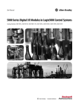
Chapter 8
Wiring Diagrams
1756-OB16IEF
ControlLogix DC (10…30V) electronically-protected, sinking or sourcing,
isolated, fast output module
1756-OB16IEF
Simplified Schematic
DC-0(+)
Isolator
Sinking Output Wiring
DC-6 (+)
Fault
ControlLogix
Backplane
Interface
DC-0 (+)
DC-2 (+)
OUT-0
Display
Jumper Bar
(Cut to Length)
Surge Current Chart
Nonisolated
Wiring
Surge
Current
4A
Continuous 2 A @ 45 °C (113°F)
2A
DC(+)
+
–
DC-0 (+)
2
1
OUT-0
DC-1 (+)
4
3
OUT-1
DC-2 (+)
6
5
OUT-2
DC-3 (+)
8
7
OUT-3
DC-4 (+)
10
9
OUT-4
DC-5 (+)
12
11
OUT-5
DC-6 (+)
14
13
OUT-6
DC-7 (+)
16
15
OUT-7
DC-8 (+)
18
17
OUT-8
DC-9 (+)
20
19
OUT-9
DC-10 (+)
22
21
OUT-10
DC-11 (+)
24
23
OUT-11
DC-12 (+)
26
25
OUT-12
DC-13 (+)
28
27
OUT-13
DC-14 (+)
30
29
OUT-14
DC-15 (+)
32
31
OUT-15
DC-15 (+)
Not Used
34
33
36
35
Not Used
Not Used
Continuous 1 A @ 60 °C (140 °F)
1A
Daisy Chain to Other RTBs
0
10 ms
Time
162
Isolated Sourcing
Output Wiring
Isolated Wiring
Rockwell Automation Publication 1756-UM058H-EN-P - May 2015
DC-0 (-)
DC-2 (-)
DC-6 (-)
Nonisolated
Sourcing
Output
Wiring
DC(-)
Additional jumper bars may be purchased
by using catalog number 1756-JMPR.
Wiring Diagrams
Chapter 8
1756-OB16IEFS
ControlLogix DC (10…30V) scheduled, electronically-protected, sinking or
sourcing, isolated, fast output module
1756-OB16IEFS
Simplified Schematic
DC-0(+)
Isolator
Sinking Output Wiring
DC-6 (+)
Fault
ControlLogix
Backplane
Interface
DC-0 (+)
DC-2 (+)
OUT-0
Display
Jumper Bar
(Cut to Length)
Surge Current Chart
Nonisolated
Wiring
Surge
Current
4A
Continuous 2 A @ 45 °C (113 °F)
2A
DC(+)
+
–
DC-0 (+)
2
1
OUT-0
DC-1 (+)
4
3
OUT-1
DC-2 (+)
6
5
OUT-2
DC-3 (+)
8
7
OUT-3
DC-4 (+)
10
9
OUT-4
DC-5 (+)
12
11
OUT-5
DC-6 (+)
14
13
OUT-6
DC-7 (+)
16
15
OUT-7
DC-8 (+)
18
17
OUT-8
DC-9 (+)
20
19
OUT-9
DC-10 (+)
22
21
OUT-10
DC-11 (+)
24
23
OUT-11
DC-12 (+)
26
25
OUT-12
DC-13 (+)
28
27
OUT-13
DC-14 (+)
30
29
OUT-14
DC-15 (+)
32
31
OUT-15
DC-15 (+)
Not Used
34
33
36
35
Not Used
Not Used
Continuous 1 A @ 60 °C (140 °F)
1A
Daisy Chain to Other RTBs
0
Isolated Sourcing
Output Wiring
Isolated Wiring
10 ms
DC-0 (-)
DC-2 (-)
DC-6 (-)
Nonisolated
Sourcing
Output
Wiring
DC(-)
Additional jumper bars may be purchased
by using catalog number 1756-JMPR.
Time
Rockwell Automation Publication 1756-UM058H-EN-P - May 2015
163
Chapter 8
Wiring Diagrams
1756-OB16IS
ControlLogix DC (10...30V) scheduled, isolated output module
Simplified Schematic
1756-OB16IS
Isolated Wiring
DC-0(+)
+5V
OUT-0
ControlLogix Backplane Interface
Display
Surge Current Chart
Surge
Current
4A
Continuous @ 30 °C (86 °F)
2A
DC-0 (+)
DC-1 (+)
DC-2 (+)
DC-2 (+)
DC-3 (+)
DC-4 (+)
Sinking Output Wiring DC-5 (+)
DC-6 (+)
DC-6 (+)
+ –
DC-7 (+)
Jumper Bar
DC-8 (+)
(Cut to Length)
DC-9 (+)
DC-10 (+)
DC-11 (+)
Nonisolated
DC-12 (+)
Wiring
DC-13 (+)
DC-14 (+)
DC-15 (+)
DC(+)
DC-15 (+)
Not Used
DC-0 (+)
2
1
4
3
6
5
8
7
10
9
12
11
14
13
16
15
18
17
20
19
22
21
24
23
26
25
28
27
30
29
32
31
34
33
36
35
DC-2 (-)
DC-6 (-)
Nonisolated
Sourcing
Output
Wiring
Not Used
Not Used
DC(-)
Continuous @ 60 °C (140 °F)
Daisy Chain to Other RTBs
0
10 ms
Time
164
OUT-0
OUT-1
OUT-2
OUT-3
OUT-4
OUT-5
OUT-6
OUT-7
OUT-8
OUT-9
OUT-10
OUT-11
OUT-12
OUT-13
OUT-14
OUT-15
Isolated Sourcing
Output Wiring
DC-0 (-)
Rockwell Automation Publication 1756-UM058H-EN-P - May 2015
Additional jumper bars may be purchased
by using catalog number 1756-JMPR.
Wiring Diagrams
Chapter 8
1756-OB32
ControlLogix DC (10...31.2V) output module
1756-OB32
Simplified Schematic
DC-0(+)
+5V
OUT-0
RTN OUT-0
ControlLogix Backplane Interface
Group 0
Daisy Chain
to Other
RTBs
Display
Surge Current Chart
Surge
1A
Current
Group 1
Continuous @ 60 °C (140 °F)
0.5 A
0
OUT-1
OUT-3
OUT-5
OUT-7
OUT-9
OUT-11
2
1
4
3
6
5
8
7
10
9
12 11
OUT-13
OUT-15
DC-0(+)
14 13
OUT-17
OUT-19
OUT-21
OUT-23
OUT-25
OUT-27
20 19
OUT-29
OUT-31
DC-1(+)
32 31
10 ms
Group 0
OUT-12
OUT-14
RTN OUT-0
16 15
18 17
OUT-16
OUT-18
OUT-20
OUT-22
OUT-24
OUT-26
22 21
24 23
26 25
28 27
30 29
Group 1
OUT-28
OUT-30
RTN OUT-1
34 33
36 35
+
Time
OUT-0
OUT-2
OUT-4
OUT-6
OUT-8
OUT-10
_
DC COM
Rockwell Automation Publication 1756-UM058H-EN-P - May 2015
165
Chapter 8
Wiring Diagrams
1756-OC8
ControlLogix DC (30...60V) output module
1756-OC8
Daisy Chain to Other RTBs
Simplified Schematic
DC-0(+)
2
1
4
3
6
5
DC-0 (+)
+5V
OUT-0
OUT-0
DC-0 (+)
RTN OUT-0
Group 0
OUT-1
Group 0
DC-0 (+)
OUT-2
8
7
10
9
12
11
14
13
16
15
DC-0 (+)
ControlLogix Backplane Interface
Display
OUT-3
RTN OUT-0
RTN OUT-0
DC-1(+)
Surge Current Chart
DC-1(+)
Group 1
Surge
4A
OUT-4
OUT-5
Group 1
DC-1(+)
OUT-6
18
17
20
19
Current
DC-1(+)
Continuous @ 60 °C (140 °F)
2A
RTN OUT-1
0
RTN OUT-1
+
10 ms
–
DC COM
Time
166
OUT-7
Rockwell Automation Publication 1756-UM058H-EN-P - May 2015
Daisy Chain to
Other RTBs
Wiring Diagrams
Chapter 8
1756-OG16
ControlLogix TTL output module
Standard Wiring
CE Compliant Wiring
1756-OG16
1756-OG16
– DC
+
2
1
OUT-1
OUT-0
4
+5 V DC
OUT-3
2
–
OUT-4
8
OUT-6
10
9
+
DC COM 0
12
13
OUT-11
TTL
Output
Device
OUT-10
16
15
18
17
20
19
OUT-15
OUT-12
–
5
8
7
10
9
12
11
14
13
16
15
18
17
20
19
OUT-4
OUT-7
OUT-8
OUT-10
OUT-13
OUT-12
OUT-15
DC-1(+)
OUT-6
DC COM 0
OUT-9
DC COM 1
OUT-0
OUT-2
OUT-11
Capacitor
0.01 μ F Typical
(See notes below.)
OUT-14
DC-1(+)
6
DC-0(+)
OUT-8
14
I/O Wire
11
OUT-9
3
OUT-5
7
DC-0(+)
4
OUT-3
5
OUT-7
1
OUT-1
OUT-2
6
OUT-13
DC Power Wire
3
OUT-5
+ DC
5V DC
Power
OUT-14
DC COM 1
Simplified Schematic
+5 DC
74AC14
OUT
74AC14
OUT
DC COM
Rockwell Automation Publication 1756-UM058H-EN-P - May 2015
167
Chapter 8
Wiring Diagrams
1756-OH8I
ControlLogix DC (90...146V) isolated output module
Simplified Schematic
DC-0
+5V
+
OUT-0
-
RTN
OUT-0
+
-
ControlLogix Backplane Interface
Display
Non-Isolated
Wiring
Surge Current Chart
Surge
Current
4A
Continuous @ 60 °C (140 °F)
2A
0
Time
10 ms
1756-OH8I
Isolated Wiring
Daisy
chain to
other
RTBs
Daisy
chain to
other
RTBs
DC-0 (+)
2
1
OUT-0
RTN OUT-0
4
3
OUT-0
DC-1 (+)
6
5
OUT-1
RTN OUT-1
DC-2 (+)
8
7
10
9
OUT-1
OUT-2
RTN OUT-2
12 11
OUT-2
DC-3 (+)
14 13
OUT-3
RTN OUT-3
16 15
OUT-3
DC-4 (+)
18 17
OUT-4
RTN OUT-4
20 19
OUT-4
DC-5 (+)
22 21
OUT-5
RTN OUT-5
24 23
OUT-5
DC-6 (+)
26 25
OUT-6
RTN OUT-6
28 27
OUT-6
DC-7 (+)
30 29
OUT-7
RTN OUT-7
32 31
OUT-7
Not used
34 33
Not used
Not used
36 35
Not used
+
168
Rockwell Automation Publication 1756-UM058H-EN-P - May 2015
– DC COM
Wiring Diagrams
Chapter 8
1756-ON8
ControlLogix AC (10...30V) output module
Simplified Schematic
1756-ON8
Daisy Chain to Other RTBs
+5V
L1-0
2
1
4
3
6
5
8
7
10
9
12
11
14
13
16
15
L1-0
OUT-0
L1-0
OUT-0
Group 0
ControlLogix Backplane Interface
OUT-1
L1-0
OUT-2
L1-0
Display
OUT-3
L1-0
Surge Current Chart
Not Used
L1-1
Surge
20 A
OUT-4
L1-1
Current
Group 1
OUT-5
L1-1
18
17
20
19
OUT-7
L1-1
0
Time
Group 1
OUT-6
L1-1
2A
Group 0
Not Used
L2
43 ms
L1
Rockwell Automation Publication 1756-UM058H-EN-P - May 2015
169
Chapter 8
Wiring Diagrams
1756-OV16E
ControlLogix DC (10...30V) electronically-fused, sinking output module
1756-OV16E
Simplified Schematic
Display
Optoisolation
DC-0(+)
Group 0
Electronic Fuse
Circuitry
1
4
3
6
5
OUT-0
OUT-3
OUT-0
ControlLogix
Backplane
Interface
2
OUT-1
OUT-2
8
7
10
9
12
11
14
13
16
15
18
17
20
19
OUT-7
RTN
OUT-0
OUT-6
RTN OUT-0
DC-0(+)
OUT-8
OUT-9
OUT-11
Surge Current Chart
Group 1
Current
OUT-10
OUT-13
OUT-12
Continuous @ 60 °C (140 °C)
RTN OUT-1
DC-1(+)
1A
0
+
10 ms
Time
–
DC COM
Daisy Chain to Other RTBs
170
Group 1
OUT-14
OUT-15
Surge
2A
Group 0
OUT-4
OUT-5
Rockwell Automation Publication 1756-UM058H-EN-P - May 2015
Daisy Chain to Other RTB
Wiring Diagrams
Chapter 8
1756-OV32E
ControlLogix DC (10...30V) electronically-fused, sinking output module
Simplified Schematic
Display
Optoisolation
DC-0(+)
OUT-0
Group 0
RTN OUT-0
ControlLogix
Backplane
Interface
Electronic Fuse
Circuitry
Surge Current Chart
Group 1
Surge
Current
2A
Continuous @ 60 °C (140 °F)
1A
0
10 ms
1756-OV32E
Daisy Chain to
Other RTBs
OUT-1
OUT-3
OUT-5
2
1
4
3
6
5
OUT-7
OUT-9
OUT-11
8
7
10
9
OUT-0
OUT-2
OUT-4
OUT-6
OUT-8
OUT-10
12 11
OUT-13
OUT-15
DC-0(+)
14 13
OUT-17
OUT-19
OUT-21
20 19
OUT-23
OUT-25
OUT-27
26 25
OUT-29
OUT-31
DC-1(+)
32 31
18 17
OUT-16
OUT-18
OUT-20
22 21
24 23
OUT-22
OUT-24
OUT-26
28 27
30 29
Group 1
OUT-28
OUT-30
RTN OUT-1
34 33
36 35
Time
Group 0
OUT-12
OUT-14
RTN OUT-0
16 15
+
Daisy Chain to
Other RTBs
_
DC COM
Rockwell Automation Publication 1756-UM058H-EN-P - May 2015
171
Chapter 8
Wiring Diagrams
1756-OW16I
ControlLogix AC (10...240V) DC (5...125V) isolated contact module
1756-OW16I
Simplified Schematic
+24V
Display
ControlLogix
Backplane
Interface
Isolated Wiring
L1-0
L1-0
L1-1
L1-2
L1-2
L1-3
DC-4 (+)
L1-4
OUT
L1-5
L1-6
L1-7
Jumper Bar
L1-8
(Cut to Length)
L1-9
L1-10
L1-11
Nonisolated
L1-12
Wiring
L1-13
Additional jumper bars may be purchased
L1-14
by using catalog number 1756-JMPR.
L1-15
L1-15
L1
Not Used
L1
2
1
4
3
6
5
8
7
10
9
12 11
14 13
16 15
18 17
20 19
22 21
24 23
26 25
28 27
30 29
32 31
34 33
36 35
L2-0
OUT-0
OUT-1 N.O.
OUT-2 N.O.
OUT-3 N.O.
OUT-4 N.O.
OUT-5 N.O.
OUT-6 N.O.
OUT-7 N.O.
OUT-8 N.O.
OUT-9 N.O.
OUT-10 N.O.
OUT-11 N.O.
OUT-12 N.O.
OUT-13 N.O.
OUT-14 N.O.
OUT-15 N.O
Not Used
Not Used
L2-2
DC-4 (-)
L2
Daisy Chain
to Other RTBs
172
Rockwell Automation Publication 1756-UM058H-EN-P - May 2015
Wiring Diagrams
Chapter 8
1756-OX8I
ControlLogix AC (10...240V) DC (5...125V) isolated contact module
1756-OX8I
Simplified Schematic
+24V
L1-0
ControlLogix
Backplane
Interface
Display
OUT-0 N.C.
OUT-0 N.O.
Additional jumper bars may be purchased
by using catalog number 1756-JMPR.
Isolated Wiring
2
1
L1-0
4
3
L1-0
L1-0
L1-1
L1-1
DC-2 (+)
L1-2
L1-2
L1-3
Jumper Bar (Cut to Length) L1-3
(Part number 97739201) L1-4
L1-4
L1-5
L1-5
L1-6
Nonisolated
Wiring
L1-6
L1-7
L1-7
L1-7
L1
Not Used
6
5
8
7
10
9
12 11
14 13
16 15
18 17
20 19
22 21
24 23
26 25
28 27
30 29
32 31
34 33
36 35
OUT-0 N.C.
OUT-0 N.O.
OUT-1 N.C.
OUT-1 N.O.
OUT-2 N.C.
OUT-2 N.O.
OUT-3 N.C.
OUT-3 N.O.
OUT-4 N.C.
OUT-4 N.O.
OUT-5 N.C.
OUT-5 N.O.
OUT-6 N.C.
OUT-6 N.O.
OUT-7 N.C.
OUT-7 N.O
Not Used
Not Used
L2-0
DC-2 (-)
L2
Daisy Chain to Other RTBs
Rockwell Automation Publication 1756-UM058H-EN-P - May 2015
173
Chapter 8
Wiring Diagrams
Notes:
174
Rockwell Automation Publication 1756-UM058H-EN-P - May 2015
Appendix
A
Troubleshoot Your Module
Topic
Page
Status Indicators for Input Modules
175
Status Indicators for Output Modules
176
Use RSLogix 5000 Software for Troubleshooting
178
This appendix describes the status indicators on the ControlLogix digital
modules and how to use them to troubleshoot the module. Each I/O module has
status indicators on the front of the module.
Status Indicators
for Input Modules
ControlLogix input modules support the status indicators described in Table 31
below. The available status indicators vary by module catalog number, as shown
in Figure 25 on page 176.
Table 31 - Status Indicators for Input Modules
Indicator
Status
Description
OK Status
Steady green
The inputs are being multicast and in a normal operating state.
Flashing green
The module has passed internal diagnostics, but is not
multicasting inputs or is inhibited.
Uninhibit the connection or establish a connection to enable
communication to the module.
Steady red
The module must be replaced.
Flashing red
Previously established communication has timed out.
Check the controller and chassis communication.
I/O Status
Yellow
The input is On.
Fault Status
Red
The input has encountered a fault.
Check the input point at the controller.
Rockwell Automation Publication 1756-UM058H-EN-P - May 2015
175
Appendix A
Troubleshoot Your Module
Figure 25 - Input Module Status Indicators by Catalog Number
1756-IB16, 1756-IB16I,
1756-IC16, 1756-IG16,
1756-IH16I, 1756-IV16
1756-IA8D, 1756-IA16
AC INPUT
DC INPUT
DC INPUT
I/O Status
Indicator
O
K
ST 0 1 2 3 4 5 6 7
Fault
Status Indicator
1756-IB16IF
FLT 0 1 2 3 4 5 6 7
OK Status
Indicator
ST
01 2 3 4 5 6 7
ST
8 9 10 11 12 13 14 15
O
K
ST
01 2 3 4 5 6 7
ST
8 9 10 11 12 13 14 15
O
K
PEER DEVICE
DIAGNOSTIC
1756-IB16D
1756-IA32, 1756-IV32
1756-IA8D, 1756-IA16I,
1756-IM16I, 1756-IN16
DC INPUT
AC INPUT
DC INPUT
ST 0 1 2 3 4 5 6 7
ST 0 1 2 3 4 5 6 7
FLT 0 1 2 3 4 5 6 7
ST 8 9 10 11 12 13 14 15
FLT 8 9 10 11 12 13 14 15
O
K
1 1 1 1 1 1
0 1 2 3 4 5
ST 8 9
ST 1
ST 6
ST 2
ST 4
DIAGNOSTIC
1
7
2
5
1
8
2
6
1
9
2
7
2
0
2
8
2
1
2
9
2
2
3
0
O
K
2
3
3
1
ST
01 2 3 4 5 6 7
ST
8 9 10 11 12 13 14 15
O
K
20945
Status Indicators
for Output Modules
ControlLogix output modules support the status indicators described in
Table 32 below. The available status indicators vary by module catalog number, as
shown in Figure 26 on page 177.
Table 32 - Status Indicators for Output Modules
176
Indicator
Status
Description
OK Status
Steady green
The outputs are actively being controlled by a system processor.
Flashing green
The module has passed internal diagnostics but is not actively controlled
or it is inhibited or controller is in Program mode.
Uninhibit connection, establish connection or transition controller to
Run mode to enable communication to module.
Steady red
The module must be replaced.
Flashing red
Previously established communication has timed out.
Check the controller and chassis communication.
I/O Status
Yellow
The output is On.
Fuse Status
Red
A short overload fault has occurred for a point in this group.
Check the wiring for a short-overload. Also check the Module Properties
dialog box in RSLogix 5000 software and reset the fuse.
Fault Status
Red
The output has encountered a fault.
Check the output point at the controller.
Diagnostic Status
Steady red
The output has encountered a fault.
Check the output point at the controller.
Flashing red
The output is listening for peer inputs and using the inputs to determine
the state of the output point.
Rockwell Automation Publication 1756-UM058H-EN-P - May 2015
Troubleshoot Your Module
Appendix A
Figure 26 - Output Module Status Indicators by Catalog Number
I/O Status Indicator
Fuse Status Indicator
1756-OA16
1756-OA16I
AC OUTPUT
AC OUTPUT
ST 0 1 2 3 4 5 6 7
O
K

FUSE
OK Status
Indicator
ST
01 2 3 4 5 6 7
ST
8 9 10 11 12 13 14 15
1756-OA8, 1756-ON8
AC OUTPUT
O
K
ST
01 2 3 4 5 6 7
O
K
ST 8 9 10 11 12 13 14 15
FUSE
Fault Status Indicator

1756-OA8D
1756-OA8E
AC OUTPUT
AC OUTPUT
O
K
ST 0 1 2 3 4 5 6 7
FLT 0 1 2 3 4 5 6 7
ST 0 1 2 3 4 5 6 7
FUSE 0 1 2 3 4 5 6 7
1756-OB16D
DC OUTPUT
ST 0 1 2 3 4 5 6 7
FLT 0 1 2 3 4 5 6 7
O
K
O
K
ST 8 9 10 11 12 13 14 15
FLT 8 9 10 11 12 13 14 15
DIAGNOSTIC
ELECTRONICALLY FUSED
DIAGNOSTIC
1756-OB16E, 1756-OV16E
1756-OB16I,
1756-OB16IS, 1756-OG16
1756-OB16IEF
DC OUTPUT
DC OUTPUT
ST 0 1 2 3 4 5 6 7
FUSE

O
K
ST 0 1 2 3 4 5 6 7
ST 8 9 10 11 12 13 14 15
DC OUTPUT
O
K
ST 8 9 10 11 12 13 14 15
FUSE

1756-OB8I, 1756-OB8I,
1756-OC8, 1756-OH8I
DC OUTPUT
DC OUTPUT
ST 0 1 2 3 4 5 6 7
ST 0 1 2 3 4 5 6 7
FLT 0 1 2 3 4 5 6 7
ST 8 9 10 11 12 13 14 15
FLT 8 9 10 11 12 13 14 15
O
K
1 1 1 1 1 1
0 1 23 4 5
ST 8 9
ST 1
ST 6
ST 2
ST 4
SCHEDULED
1
7
2
5
1
8
2
6
1
9
2
7
2
0
2
8
2
1
2
9
2
2
3
0
O
K
1756-OW16I
DC OUTPUT
RELAY OUTPUT
O
K
ST 0 1 2 3 4 5 6 7
2
3
3
1
1756-OB8EI
FUSE 0 1 2 3 4 5 6 7
ST 8 9 10 11 12 13 14 15
DIAG 8 9 10 11 12 13 14 15
O
K
1756-OB32, 1756-OV32E
DC OUTPUT
ST 0 1 2 3 4 5 6 7
ST 0 1 2 3 4 5 6 7
DIAG 0 1 2 3 4 5 6 7
PEER DEVICE
ELECTRONICALLY FUSED
1756-OB16IEFS
Diagnostic
Status
Indicator
ST 0 1 2 3 4 5 6 7
ST 8 9 10 11 12 13 14 15
O
K
1756-OX8I
O
K
RELAY OUTPUT
ST 0 1 2 3 4 5 6 7
O
K
ELECTRONICALLY FUSED
Rockwell Automation Publication 1756-UM058H-EN-P - May 2015
177
Appendix A
Troubleshoot Your Module
Use RSLogix 5000 Software
for Troubleshooting
In addition to the status indicator display on the module, RSLogix 5000 software
alerts you to fault conditions.
Fault conditions are reported in these ways:
• Warning signal on the main screen next to the module—This occurs when
the connection to the module is broken.
• Message in a screen’s status line.
• Notification in the Tag Editor—General module faults are also reported in
the Tag Editor. Diagnostic faults are reported only in the Tag Editor.
• Status on the Module Info tab.
The following windows display fault notification in RSLogix 5000 software.
As shown in Figure 27, a warning icon
when a communication fault occurs.
Figure 27 - Warning Signal on Main Screen
178
Rockwell Automation Publication 1756-UM058H-EN-P - May 2015
appears in the I/O Configuration tree
Troubleshoot Your Module
Appendix A
As shown in Figure 28, major and minor faults are listed on the Module Info tab
in the Status section.
Figure 28 - Fault Message in Status Line
As shown in Figure 29, the Value field displays 65535 to indicate the module
connection has been broken.
Figure 29 - Notification in Tag Editor
Fault Type Determination
When you are monitoring a module’s configuration properties in RSLogix 5000
software and receive a Communication fault message, the Connection tab lists
the type of fault under Module Fault.
Rockwell Automation Publication 1756-UM058H-EN-P - May 2015
179
Appendix A
Troubleshoot Your Module
Notes:
180
Rockwell Automation Publication 1756-UM058H-EN-P - May 2015
Appendix
B
Tag Definitions
Topic
Page
Standard and Diagnostic Input Module Tags
181
Standard and Diagnostic Output Module Tags
184
Fast Input Module Tags
187
Fast Output Module Tags
192
Array Data Structures
209
This appendix describes the tags that are used for standard, diagnostic, and fast
input and output modules.
Module-defined data types and tags are created when a module is initiated. The
set of tags associated with any module depends on the type of module and the
communication or connection format chosen during configuration.
Standard and Diagnostic
Input Module Tags
ControlLogix standard and diagnostic input modules have two types of tags:
• Configuration—Structure of data sent from the controller to the I/O
module upon powerup.
• Input—Structure of data continually sent from the I/O module to the
controller containing the current operational status of the module.
IMPORTANT
The table lists all possible standard and diagnostic input module tags. In each
application, the series of tags varies, depending on how the module is
configured.
Rockwell Automation Publication 1756-UM058H-EN-P - May 2015
181
Appendix B
Tag Definitions
Table 33 - Standard Input Module Configuration Tags
Name
Data Type
Definition
COSOnOffEn
(1bit per point)
DINT
Change of State On to Off—Causes updated data to be sent to the controller immediately after an input for an On to Off
transition of the masked input points. The CST timestamp also is updated. May be used to trigger an event task in the
controller.
0 = Disable
1 = Enable
COSOffOnEn
(1 bit per point)
DINT
Change of State Off to On—Causes updated data to be sent to the controller immediately after an input for an Off to On
transition of the masked input points. The CST timestamp also is updated. May be used to trigger an event task in the
controller.
0 = Disable
1 = Enable
FilterOnOff_0_7…
(1 byte per group)
SINT
Filter Times On to Off—Filter time for digital filter in digital input modules for On to Off transition. Operates on groups
of eight points.
Valid DC filter times = 0, 1, 2, 9, 18 ms
Valid AC filter times = 1, 2 ms
FilterOffOn_0_7…
(1 byte per group)
SINT
Filter Times Off to On—Filter time for digital filter in digital input modules for Off to On transition. Operates on groups
of eight points.
Valid DC filter times = 0, 1, 2 ms
Valid AC filter times = 1, 2 ms
Table 34 - Standard Input Module Data Tags
Name
Data Type
Definition
CSTTimestamp
(8 bytes)
DINT[2]
Coordinated System Time Timestamp—Timestamp can be configured to indicate the time that data changed (see
COSOffOnEn, COSOnOffEn, COSStatus, DiagCOSDisable) and/or the time that a diagnostic fault occurred (see OpenWireEn,
Field PwrLossEn).
Data
(1 bit per point)
DINT
Off/On—Status for each input point.
0 = Off
1 = On
Fault
(1 bit per point)
DINT
Fault Status—An an ordered status of faults that indicates a point is faulted and input data for that point may be
incorrect. Check other diagnostic faults, if they are available, for further diagnosis of the root cause. If communication to
the input module is lost, then all points for the module are faulted.
0 = No fault
1 = Fault (OpenWire or FieldPwrLoss or Comm Fault)
Table 35 - Diagnostic Input Module Configuration Tags
Name
Data Type
Definition
COSOnOffEn
(1bit per point)
DINT
Change of State On to Off—Triggers an event in the controller for On to Off transition of input point and causes the
input module to update the data table as soon as possible. The CST timestamp is also updated.
0 = Disable
1 = Enable
COS OffOnEn
(1 bit per point)
DINT
Change of State Off to On—Triggers an event in the controller for Off to On transition of input point and causes the
input module to update the data table as soon as possible. The CST timestamp is also updated.
0 = Disable
1 = Enable
DiagCOSDisable
(1 bit per point)
BOOL
Diagnostic Change of State—Triggers the module to transmit diagnostic status data with an updated timestamp as
soon as the diagnostic data changes state.
FaultLatchEn
(1 bit per point)
DINT
Latch Fault—If enabled for a point, any OpenWire or FieldPwrLoss stays latched in the faulted state even if the fault no
longer exists until you clear the fault.
0 = Disable
1 = Enable latching
FieldPwrLossEn
(1 bit per point)
DINT
Field Power Loss—Enables Field Power Loss diagnostic.
0 = Disable
1 = Enable
182
Rockwell Automation Publication 1756-UM058H-EN-P - May 2015
Tag Definitions
Appendix B
Table 35 - Diagnostic Input Module Configuration Tags (continued)
Name
Data Type
Definition
FilterOnOff_0_7…
(1 byte per group)
SINT
Filter Time On to Off—Filter time for digital filter in digital input modules for On to Off transition. Operates on groups of
eight points.
Valid DC filter times = 0, 1, 2, 9, 18 ms.
Valid AC filter times = 1, 2 ms.
FilterOffOn_0_7…
(1 byte per group)
SINT
Filter Time Off to On—Filter time for digital filter in digital input modules for Off to On transition. Operates on groups of
eight points.
Valid DC filter times = 0, 1, 2 ms.
Valid AC filter times = 1, 2 ms.
OpenWireEn
(1 bit per point)
DINT
Open Wire—Enables Open Wire diagnostic.
0 = Disable.
1 = Enable.
Table 36 - Diagnostic Input Module Data Tags
Name
Data Type
Definition
CSTTimestamp
(8 bytes)
DINT[2]
Coordinated System Time Timestamp—Timestamp can be configured to indicate the time that data changed (see
COSOffOnEn, COSOnOffEn, COSStatus, DiagCOSDisable) and/or the time that a diagnostic fault occurred (see OpenWireEn,
Field PwrLossEn).
Data
(1 bit per point)
DINT
Input Status—On/Off status for each input point.
0 = Off
1 = On
Fault
(1 bit per point)
DINT
Fault Status—An ordered status of faults that indicates a point is faulted and input data for that point may be incorrect.
Check other diagnostic faults, if they are available, for further diagnosis of the root cause. If communication to the input
module is lost or inhibited, then all points for the module are faulted by the processor.
0 = No fault
1 = Fault (OpenWire or FieldPwrLoss or Comm Fault)
FieldPwrLoss
(1 bit per point)
DINT
Field Power Loss—AC input diagnostic detects that field power has failed or is disconnected from the module. Open
Wire also is detected.
0 = No fault
1 = Fault
OpenWire
(1 bit per point)
DINT
Open Wire—Diagnostic that detects that a wire has been disconnected from the input point. If a group of points shows
this fault, then possible the return (L1 or GND) is missing from the module. Also see FieldPwrLoss.
0 = No fault
1 = Fault
Rockwell Automation Publication 1756-UM058H-EN-P - May 2015
183
Appendix B
Tag Definitions
Standard and Diagnostic
Output Module Tags
ControlLogix standard and diagnostic digital output modules have three types of
tags:
• Configuration—Structure of data sent from the controller to the I/O
module upon powerup.
• Input—Structure of data continually sent from the I/O module to the
controller containing the current operational status of the module.
• Output—Structure of data continually sent from the controller to the I/O
module that can modify the module behavior.
IMPORTANT
The table lists all possible standard or diagnostic output module tags. In each
application, the series of tags varies, depending on how the module is
configured.
Table 37 - Standard Output Module Configuration Tags
Name
Data Type
Definition
FaultMode
(1bit per point)
DINT
Fault Mode—Used in conjunction with FaultValue to configure the state of outputs when a communication fault occurs.
See FaultValue.
0 = Use FaultValue (Off or On)
1 = Hold Last State
FaultValue
(1 bit per point)
DINT
Fault Value—Used in conjunction with FaultMode to configure the state of outputs when a communication fault occurs.
See FaultMode.
0 = Off
1 = On
ProgMode
(1 bit per point)
DINT
Program Mode—Used in conjunction with ProgValue to configure the state of outputs when the controller is in Program
mode. See ProgValue.
0 = Use ProgValue (Off or On)
1 = Hold Last State
ProgValue
(1 bit per point)
DINT
Program Value—Used in conjunction with ProgMode to configure the state of outputs when the controller is in Program
mode. See ProgMode.
0 = Off
1 = On
ProgToFaultEn
(1 byte per module)
BOOL
Program to Fault Transition—Diagnostic enables the transition of outputs to FaultMode if a communication failure
occurs in Program mode. Otherwise outputs remain in Program mode. See ProgMode, ProgValue, FaultMode, FaultValue.
0 = Outputs stay in Program mode if a communication failure occurs.
1 = Outputs go to FaultMode if a communication failure occurs.
184
Rockwell Automation Publication 1756-UM058H-EN-P - May 2015
Tag Definitions
Appendix B
Table 38 - Standard Output Module Input Data Tags
Name
Data Type
Definition
CSTTimestamp
(8 bytes)
DINT[2]
Coordinated System Time Timestamp—Timestamp of diagnostic input data including fusing (see BlownFuse,
NoLoad, OutputVerifyFault, FieldPwrLoss), which is updated whenever a diagnostic fault occurs or goes away.
Data
(1 bit per point)
DINT
Data—Off/On status for the output point echoed back from the output module. This is used to verify proper
communication only. No field side verification is done. For field side verification, see OutputVerifyFault.
0 = Off
1 = On
Fault
(1 bit per point)
DINT
Fault—This is an ordered status of faults that indicates a point is faulted and I/O data for that point may be incorrect.
Check other diagnostic faults, if they are available, for further diagnosis of the root cause. If communication to the input
module is lost, then all points for the module are faulted.
0 = No fault
1 = Fault (FuseBlown, NoLoad, OutputVerifyFault, FieldPwrLoss, or CommFault)
FuseBlown
(1 bit per point)
DINT
Fuse Is Blown—An electronic or mechanical fuse has detected a short or overload condition for an output point. All
FuseBlown conditions are latched and must be reset by the user.
0 = No fault
1 = Fault
Table 39 - Standard Output Module Output Data Tags
Name
Data Type
Definition
CSTTimestamp
(8 bytes)
DINT[2]
Coordinated System Time Timestamp—Timestamp to be used with scheduled outputs and coordinated system time
(CST). Used to synchronize outputs across the system by indicating the time (CST timestamp) at which the output module
is to apply its outputs.
Data
(1 bit per point)
DINT
Output Status—On/Off status of the output point originating from the controller.
0 = Off
1 = On
Table 40 - Diagnostic Output Module Configuration Tags
Name
Data Type
Definition
FaultLatchEn
(1bit per point)
DINT
Latch Fault—If enabled for a point, any NoLoad, OutputVerifyFault or FieldPwrLoss stays latched in the faulted state
even if the fault no longer exists until the user clears the fault. This does not affect FuseBlown; it is always latched.
0 = Disable
1 = Enable latching
FaultMode
(1bit per point)
DINT
Fault Mode—Used in conjunction with FaultValue to configure the state of outputs when a communication fault occurs.
See FaultValue.
0 = Use FaultValue (Off or On)
1 = Hold Last State
FaultValue
(1 bit per point)
DINT
Fault Value—Used in conjunction with FaultMode to configure the state of outputs when a communication fault occurs.
See FaultMode.
0 = Off
1 = On
FieldPwrLoss
(1 bit per point)
DINT
Field Power Loss—Enables Field Power Loss diagnostic.
0 = Disable
1 = Enable
NoLoadEn
(1 bit per point)
DINT
No Load—Enables No Load diagnostic.
0 = Disable
1 = Enable
OutputVerifyEn
(1 bit per point)
DINT
Output Verify—Enables Output Verify diagnostic.
0 = Disable
1 = Enable
Rockwell Automation Publication 1756-UM058H-EN-P - May 2015
185
Appendix B
Tag Definitions
Table 40 - Diagnostic Output Module Configuration Tags (continued)
Name
Data Type
Definition
ProgMode
(1 bit per point)
DINT
Program Mode—Used in conjnunction with ProgValue to configure the state of outputs when the controller is in
Program mode. See ProgValue.
0 = Use ProgValue (Off or On)
1 = Hold Last State
ProgValue
(1 bit per point)
DINT
Program Value—Used in conjunction with ProgMode to configure the state of outputs when the controller is in Program
mode. See ProgMode.
0 = Off
1 = On
ProgToFaultEn
(1 byte per module)
BOOL
Program to Fault Transition—Diagnostic enables the transition of outputs to FaultMode if a communication failure
occurs in Program mode. Otherwise outputs remain in Program mode. See ProgMode, ProgValue, FaultMode, FaultValue.
0 = Outputs stay in Program mode if a communication failure occurs.
1 = Outputs go to FaultMode if a communication failure occurs.
Table 41 - Diagnostic Output Module Input Data Tags
Name
Data Type
Definition
CSTTimestamp
(8 bytes)
DINT[2]
Coordinated System Time Timestamp—Timestamp of diagnostic input data including fusing (see BlownFuse,
NoLoad, OutputVerifyFault, FieldPwrLoss), which is updated whenever a diagnostic fault occurs or goes away.
Data
(1 bit per point)
DINT
Output Echo Status—Off/On status for the output point echoed back from the output module. This is used to verify
proper communication only. No field side verification is done. For field side verification, see OutputVerifyFault.
0 = Off
1 = On
Fault
(1 bit per point)
DINT
Fault Status—Indicates whether a point is faulted. Faulted I/O data for that point may be incorrect. Check other
diagnostic faults, if they are available, for further diagnosis of the root cause. If communication to the input module is lost
or inhibited, then all points for the module are faulted by the processor.
0 = No fault
1 = Fault (FuseBlown, NoLoad, OutputVerifyFault, FieldPwrLoss, or CommFault)
FieldPwrLoss
(1 bit per point)
DINT
Field Power Loss—AC output diagnostic detects that field power has failed or is disconnected from the module. No Load
also is detected.
0 = No fault
1 = Fault
FuseBlown
(1 bit per point)
DINT
Fuse Is Blown—An electronic or mechanical fuse has detected a short-circuit condition for an output point. All
FuseBlown conditions are latched and must be reset by the user.
0 = No fault
1 = Fault
NoLoad
(1 bit per group)
DINT
No Load—Diagnostic that indicates the absence of a load (such as, the wire is disconnected from the module). This
diagnostic operates only in the Off state
0 = No fault
1 = Fault
OutputVerifyFault
(1 bit per point)
DINT
Output Verify—Diagnostic that indicates that the input has been commanded to the On state but the output has not
been verified to be On.
0 = No fault
1 = Fault (output is not On)
Table 42 - Diagnostic Output Module Output Data Tags
Name
Data Type
Definition
CSTTimestamp
(8 bytes)
DINT[2]
Coordinated System Time Timestamp—Timestamp to be used with scheduled outputs and coordinated system time
(CST). Used to synchronize outputs across the system by indicating the time (CST timestamp) at which the output module
is to apply its outputs.
Data
(1 bit per point)
DINT
Output Status—Status for the output point originating from the controller.
0 = Off
1 = On
186
Rockwell Automation Publication 1756-UM058H-EN-P - May 2015
Tag Definitions
Fast Input Module Tags
Appendix B
The ControlLogix 1756-IB16IF fast input module has four types of tags:
• Configuration—Structure of data sent from the controller to the I/O
module upon powerup.
• Input—Structure of data continually sent from the I/O module to the
controller or a listening peer module containing the current operational
status of the module.
• Output—Structure of output data processed by the input module.
IMPORTANT
In RSLogix 5000 software, version 18.02.00 and 19.01.00, output tag
information is sent to the 1756-IB16IF module only at the RPI rate defined
during configuration. For optimal performance, use an Immediate Output (IOT)
instruction.
For example, the rung shown below contains an IOT instruction for a fast input
module in slot 3. Add a similar rung to your last routine within the Main Task to
mimic normal output tag processing.
• Event—Structure of event data continually sent from the I/O module to
the controller or a listening module containing the current operational
status of the module.
Fast input modules use array data structures. Array data structures differ from the
flat data structures of other digital I/O modules. For more information, see Array
Data Structures on page 209.
IMPORTANT
The Module Definition column in each table lists the connection type and input
data type combinations that are required to create the corresponding tag. For
more information about defining connection and input data types, see Create a
New Module on page 125.
Rockwell Automation Publication 1756-UM058H-EN-P - May 2015
187
Appendix B
Tag Definitions
Table 43 - 1756-IB16IF Module Configuration Tags
Name
Data Type
Tag Definition
Module Definition
LatchTimestamps
BOOL
Latch Timestamps—Latches a CIP Sync timestamp for a COS transition:
• When an initial timestamp is latched, timestamps for subsequent COS transitions are
dropped.
• Once a latched timestamp is acknowledged via the corresponding bit in the
Pt[x].NewDataOffOnAck or Pt[x].NewDataOnOffAck tag, the timestamp is overridden
upon the next COS transition.
Requires COS to be enabled via the Pt[x].COSOffOnEn or Pt[x].COSOnOff tags. For more
information, see page 83.
0 = Timestamps are overridden with each successive COS transition.
1 = Timestamps are latched until acknowledged.
Connection = Data
Input Data = Data or Timestamp Data
or
Connection = Data with Event
Input Data = Timestamp Data
FilterOffOn
INT
Filter Time Off to On—Defines how long an Off to On input transition must remain in the Connection = Data
On state before the module considers the transition valid. For more information, see page 86. Input Data = Data or Timestamp Data
Valid filter time = 0…30,000 μs
or
Connection = Data with Event
Input Data = Timestamp Data
FilterOnOff
INT
Filter Time On to Off—Defines how long an On to Off input transition must remain in the Connection = Data
Off state before the module considers the transition valid. For more information, see page 86. Input Data = Data or Timestamp Data
Valid filter time = 0…30,000 μs
or
Connection = Data with Event
Input Data = Timestamp Data
Pt[x].FilterEn
BOOL
Filter—If enabled for a point, input transitions must remain in the new state for a
configured length of time before the module considers the transition valid. For more
information, see page 86.
0 = Filtering is disabled.
1 = Filtering is enabled.
Connection = Data
Input Data = Data or Timestamp Data
or
Connection = Data with Event
Input Data = Timestamp Data
Pt[x].COSOffOnEn
BOOL
Change of State Off to On—If enabled for a point, an Off to On transition triggers a
timestamp recording and sends a COS message on the backplane. For more information, see
page 48.
0 = COS data is not produced upon an Off to On transition.
1 = COS data is produced upon an Off to On transition.
Connection = Data
Input Data = Data or Timestamp Data
or
Connection = Data with Event
Input Data = Timestamp Data
Pt[x].COSOnOffEn
BOOL
Change of State On to Off—If enabled for a point, an On to Off transition triggers a
timestamp recording and sends a COS message on the backplane. For more information, see
page 48.
0 = COS data is not produced upon an On to Off transition.
1 = COS data is produced upon an On to Off transition.
Connection = Data
Input Data = Data or Timestamp Data
or
Connection = Data with Event
Input Data = Timestamp Data
Table 44 - 1756-IB16IF Module Input Tags
Name
Data Type
Tag Definition
Module Definition
Fault
DINT
Fault Status—Indicates whether a point is faulted. If communication to the input
module is lost, then all 32 bits are set. For more information, see page 103.
0 = No fault
1 = Fault
Connection = Data or Listen Only
Input Data = Data or Timestamp Data
or
Connection = Data with Event or Listen
Only with Event
Input Data = Timestamp Data
LocalClockOffset
DINT
Local Clock Offset—Indicates the offset in microseconds between the current CST and
the CIP Sync value when a valid CIP Sync time is available.
Connection = Data, Data with Event,
Listen Only, or Listen Only with Event
Input Data = Timestamp Data
OffsetTimestamp
DINT
Timestamp Offset—Indicates when the CIP Sync time was last updated. The timestamp
is in CIP Sync time.
Connection = Data, Data with Event,
Listen Only, or Listen Only with Event
Input Data = Timestamp Data
GrandMasterClockID
DINT
Grandmaster Clock ID—Indicates the ID of the CIP Sync Grandmaster to which the
module is synced.
Connection = Data, Data with Event,
Listen Only, or Listen Only with Event
Input Data = Timestamp Data
188
Rockwell Automation Publication 1756-UM058H-EN-P - May 2015
Tag Definitions
Appendix B
Table 44 - 1756-IB16IF Module Input Tags (continued)
Name
Data Type
Tag Definition
Module Definition
Pt[x].Data
BOOL
Input Status—Indicates whether an input point is On or Off.
0 = The input point is Off.
1 = The input point is On.
Connection = Data or Listen Only
Input Data = Data or Timestamp Data
or
Connection = Data with Event or Listen
Only with Event
Input Data = Timestamp Data
Pt[x].Fault
BOOL
Quality of Data after Fault—Indicates whether input data for a faulted point is correct
or incorrect.
0 = No fault
1 = Fault
Connection = Data or Listen Only
Input Data = Data or Timestamp Data
or
Connection = Data with Event or Listen
Only with Event
Input Data = Timestamp Data
Pt[x].NewDataOffOn
BOOL
New Data Off to On—Captures short duration pulses for Off to On transitions. A
captured pulse remains latched until acknowledged via the Pt[x].NewDataOffOnAck
output tag. For more information, see page 82.
0 = No new Off to On transitions have occurred since the last acknowledgement.
1 = A new Off to On transition has occurred, but has not yet been acknowledged.
Connection = Data or Listen Only
Input Data = Data or Timestamp Data
or
Connection = Data with Event or Listen
Only with Event
Input Data = Timestamp Data
Pt[x].NewDataOnOff
BOOL
New Data On to Off—Captures short duration pulses for On to Off transitions. A pulse
remains latched until acknowledged via the Pt[x].NewDataOnOffAck output tag. For more
information, see page 82.
0 = No new On to Off transitions have occurred since the last acknowledgement.
1 = A new On to Off transition has occurred, but has not yet been acknowledged.
Connection = Data or Listen Only
Input Data = Data or Timestamp Data
or
Connection = Data with Event or Listen
Only with Event
Input Data = Timestamp Data
Pt[x].TimestampDropped
BOOL
Dropped Timestamp—Indicates whether a timestamp was lost as a result of one of the Connection = Data, Data with Event,
following:
Listen Only, or Listen Only with Event
• The corresponding bit was set in the LatchTimestamps configuration tag, so a new
Input Data = Timestamp Data
timestamp was not recorded because the previous timestamp was latched.
• The corresponding bit in the LatchTimestamps configuration tag was not set, but a
timestamp was replaced by a new timestamp because the previous timestamp was not
acknowledged via the Pt[x].NewDataOffOnAck or Pt[x].NewDataOnOffAck output tags.
0 = A timestamp was not dropped.
1 = A timestamp was dropped.
Pt[x].CIPSyncValid
BOOL
CIP Sync Is Valid—Indicates whether CIP Sync is available on the backplane.
0 = CIP Sync is not available.
1 = CIP Sync is available.
Connection = Data, Data with Event,
Listen Only, or Listen Only with Event
Input Data = Timestamp Data
Pt[x].CIPSyncTimeout
BOOL
CIP Sync Timeout—Indicates whether a valid time master on the backplane has timed
out.
0 = A time master is either not detected on the backplane or is valid. See
Pt[x].CIPSyncValid.
1 = A valid time master was detected on the backplane, but the time master has timed
out.
Connection = Data, Data with Event,
Listen Only, or Listen Only with Event
Input Data = Timestamp Data
Pt[x].InputOverrideStatus
BOOL
Input Override Status—Indicates whether local inputs are being overridden by the
value in the Pt.[x].DataOverrideValue output tag because the corresponding bit in the
Pt[x].DataOverrideEn output tag is set.
0 = Inputs are not being overridden.
1 = Inputs are being overridden.
Connection = Data, Data with Event,
Listen Only, or Listen Only with Event
Input Data = Timestamp Data
Pt[x].Timestamp.OffOn
DINT
Off to On Timestamp—Records a 64-bit timestamp for the input point’s last transition
to On. The timestamp is in CIP Sync time.
Connection = Data, Data with Event,
Listen Only, or Listen Only with Event
Input Data = Timestamp Data
Pt[x].Timestamp.OnOff
DINT
On to Off Timestamp—Records a 64-bit timestamp for the input point’s last transition
to Off. The timestamp is in CIP Sync time.
Connection = Data, Data with Event,
Listen Only, or Listen Only with Event
Input Data = Timestamp Data
Rockwell Automation Publication 1756-UM058H-EN-P - May 2015
189
Appendix B
Tag Definitions
Table 45 - 1756-IB16IF Module Output Tags
Name
Data Type
Tag Definition
Module Definition
ResetTimestamps
BOOL
Reset Timestamp—When set, clears all timestamps when a rising edge occurs.
0 = Timestamps are not reset.
1 = Timestamps are reset when a rising edge occurs.
Connection = Data or Data with Event
Input Data = Timestamp Data
ResetEvents
BOOL
Reset Event—When set, clears all events in the Event[x].NewEvent and
Event[x].Timestamp tags when a rising edge occurs.
0 = Events are not cleared.
1 = Events are cleared when a rising edge occurs.
Connection = Data with Event
Input Data = Timestamp Data
LatchEvents
BOOL
Latch Event—When set, latches an event until the event is acknowledged. Once
acknowledged, the event is overridden by a new event.
0 = Events are overridden by new events.
1 = Events are latched until acknowledged, and new events are ignored.
Connection = Data with Event
Input Data = Timestamp Data
Pt[x].NewDataOffOnAck
BOOL
Acknowledge Off to On Transition—A rising edge acknowledges Off to On transitions
by clearing the corresponding bits in the Pt[x].Timestamp.OffOn[x] and
Pt[x].NewDataOffOn input tags.
0 = Off to On transitions are not acknowledged.
1 = Off to On transitions are acknowledged on the initial tranisition to 1 of this bit.
Connection = Data
Input Data = Data or Timestamp Data
or
Connection = Data with Event
Input Data = Timestamp Data
Pt[x].NewDataOnOffAck
BOOL
Acknowledge On to Off Transition—A rising edge acknowledges On to Off transitions
by clearing the corresponding bits in the Pt[x].Timestamp.OnOff[x] and
Pt[x].NewDataOnOff input tags.
0 = On to Off transitions are not acknowledged.
1 = On to Off transitions are acknowledged on the initial tranisition to 1 of this bit.
Connection = Data
Input Data = Data or Timestamp Data
or
Connection = Data with Event
Input Data = Timestamp Data
Pt[x].DataOverrideEn
BOOL
Override Data—When set, simulates an input transition when in Run mode by
overriding the actual input state with the value defined in the Pt[x].DataOverrideValue
output tag. This function is useful for validating timestamping.
0 = The state of an input device is not being overridden.
1 = The state of an input device is being overridden by the value defined in the
Pt[x].DataOverride output tag.
Connection = Data or Data with Event
Input Data = Timestamp Data
Pt[x].DataOverrideValue
BOOL
Override Data Value—Defines the value to be applied to the input point when the
corresponding bit in the Pt[x].DataOverrideEn tag is enabled.
0 = The input state is Off. A timestamp is recorded in the Pt[x].Timestamp.OnOff[x] input
tag on a falling edge.
1 = The input state is On. A timestamp is recorded in the Pt[x].Timestamp.OffOn[x] input
tag on a rising edge.
Connection = Data or Data with Event
Input Data = Timestamp Data
Event[x].Mask
INT
Event Mask—When enabled for a point, an event is triggered when the state of the input
matches the value of the corresponding bits in the Event[x].Value tag. For more
information, see page 89.
Connection = Data with Event
Input Data = Timestamp Data
Event[x].Value
INT
Event Value—Defines whether an input point must be in the On or Off state before an
event is triggered. An event is only triggered if the corresponding bits in the Event[x].Mask
tag is enabled. For more information, see page 89.
0 = The input must be in the Off state to trigger an event.
1 = The input must be in the On state to trigger an event.
Connection = Data with Event
Input Data = Timestamp Data
Event[x].Disarm
BOOL
Disarm Event—Prevents events from being triggered for a point via the pattern defined
in the Event[x].Mask and Event[x].Value tags. For more information, see page 89.
0 = Events are triggered.
1 = Events are not triggered.
Connection = Data with Event
Input Data = Timestamp Data
Event[x].NewEventAck
BOOL
Acknowledge New Event—When set, acknowledges a new event has occurred as
indicated by the Event[x].NewEvent event tag.
0 = A new event has not been acknowledged.
1 = A new event has been acknowledged.
Connection = Data with Event
Input Data = Timestamp Data
190
Rockwell Automation Publication 1756-UM058H-EN-P - May 2015
Tag Definitions
Appendix B
Table 46 - 1756-IB16IF Module Event Tags
Name
Data Type
Tag Definition
Module Definition
Fault
DINT
Fault Status—Indicates whether a point is faulted. If communication to the input
module is lost, then all 32 bits are set. For more information, see page 103.
0 = No fault has occurred.
1 = A fault has occurred.
Connection = Data with Event or Listen
Only with Event
Input Data = Timestamp Data
Event[x].NewEvent
BOOL
New Event—Indicates whether a new event has occurred. This bit is cleared only when
acknowledged by the Event[x].NewEventAck output tag or reset by the ResetEvents
output tag.
0 = No new event has occurred since the last acknowledged event.
1 = A new event has occurred since the last acknowledged event.
Connection = Data with Event or Listen
Only with Event
Input Data = Timestamp Data
Event[x].EventDropped
BOOL
Event Dropped—Indicates whether an event has been dropped:
Connection = Data with Event or Listen
Only with Event
• If the LatchEvents output tag is set, the last recorded event is retained until
acknowledged, and a subsequent event is dropped.
Input Data = Timestamp Data
• If the LatchEvents output tag is cleared, the last unacknowledged event is overwritten.
0 = An event has not been dropped.
1 = An event has been dropped.
Event[x].CIPSyncValid
BOOL
CIP Sync Valid—Indicates whether a valid CIP Sync time master existed on the
backplane at the time of an event.
0 = CIP Sync was not available on the backplane at the time of an event.
1 = CIP Sync was available on the backplane at the time of an event.
Connection = Data with Event or Listen
Only with Event
Input Data = Timestamp Data
Event[x].CIPSyncTimeout
BOOL
CIP Sync Timout—Indicates that a valid CIP Sync time master existed on the backplane
at the time of an event, but has since timed out.
0 = CIP Sync has not timed out.
1 = CIP Sync was available on the backplane, but has since timed out prior to the event
occurring.
Connection = Data with Event or Listen
Only with Event
Input Data = Timestamp Data
Event[x].Data
INT
Module Data—Shows the input data for all 16 points on the module at the time an
event occurs. Data for bits 0…15 is shown as a bit mask where bit 0 is Pt[0].Data and bit
15 is Pt[15].Data.
0 = On a per bit basis, indicates the corresponding bit in the Pt[x].Data input tag was Off
when the event occurred.
1 = On a per bit basis, indicates the corresponding bit in the Pt[x].Data input tag was On
when the event occurred.
Connection = Data with Event or Listen
Only with Event
Input Data = Timestamp Data
Event[x].Timestamp
DINT
Event Timestamp—Records a 64-bit timestamp in CIP Sync format at the time an
event occurs.
Connection = Data with Event or Listen
Only with Event
Input Data = Timestamp Data
Rockwell Automation Publication 1756-UM058H-EN-P - May 2015
191
Appendix B
Tag Definitions
Fast Output Module Tags
ControlLogix fast output modules have three types of tags:
• Configuration—Structure of data sent from the controller to the I/O
module upon powerup.
• Input—Structure of data continually sent from the I/O module to the
controller containing the current operational status of the module.
• Output—Structure of data continually sent from the controller to the I/O
module that can modify the module behavior.
IMPORTANT
The Module Definition column in each table lists the connection type and input
data type combinations that are required to create the corresponding tag. For
more information about defining connection and input data types, see Create a
New Module on page 125.
Topic
Page
1756-OB16IEF Module
192
1756-OB16IEFS Module
200
1756-OB16IEF Module
IMPORTANT
In RSLogix 5000 software, version 18.02.00 and 19.01.00, output tag
information is sent to the 1756-OB16IEF module only at the RPI rate defined
during configuration. For optimal performance, use an Immediate Output (IOT)
instruction.
For example, the rung shown below contains an IOT instruction for a fast
output module in slot 3. Add a similar rung to your last routine within the Main
Task to mimic normal output tag processing.
The 1756-OB16IEF module uses array data structures. Array data structures
differ from the flat data structures of other digital I/O modules. For more
information, see Array Data Structures on page 209.
192
Rockwell Automation Publication 1756-UM058H-EN-P - May 2015
Tag Definitions
Appendix B
Table 47 - 1756-OB16IEF Module Configuration Tags
Name
Data Type
Tag Definition
Module Definition
ProgToFaultEn
BOOL
Program to Fault Mode—Enables the transition of outputs to Fault mode if a
communication failure occurs in Program mode. Otherwise, outputs remain in Program
mode. See Pt[x].FaultMode, Pt[x]FaultValue Pt[x]ProgMode, and Pt[x]ProgValue.
0 = Outputs stay in Program mode if communication fails.
1 = Outputs go to Fault mode if communication fails.
Connection = Data
Output Data = Data or Scheduled
per Module
or
Connection = Peer Ownership
Output Data = Data with Peer
InputPartnerSlot
SINT
Peer Partner Slot—Identifies the slot number of the local chassis where the peer input
module resides.
Valid values:
• 0…16
• -1 = No input module has been identified as a peer.
Connection = Peer Ownership
Output Data = Data with Peer
InputPartnerID
SINT
Peer Partner ID—Identifies the peer input module that controls outputs on the
1756-OB16IEF module. The type of module determines the connection type of format of
input data.
Valid values:
0 = None (default)
1 = 1756-IB16IF
2 = 1756-LSC8XIB8I
Connection = Peer Ownership
Output Data = Data with Peer
Pt[x].FaultMode
BOOL
Fault Mode—Used in conjunction with the Pt[x].FaultValue tag to determine the state of
outputs when a communication failure occurs.
0 = Uses the output value defined in the Pt[x].FaultValue configuration tag (default).
1 = Holds the last state of the output for the length of time defined in the
Pt[x].FaultValueStateDuration tag. If PWM is enabled for the output point and the output
is currently On, the output continues PWM until the cycle limit is reached or a final fault
state goes into effect via the Pt[x].FaultFinalState tag.
Connection = Data
Output Data = Data or Scheduled
per Module
or
Connection = Peer Ownership
Output Data = Data with Peer
Pt[x].FaultValue
BOOL
Fault Value—Defines the output value when a fault occurs. Holds the configured state of
the output for the length of time defined in the Pt[x].FaultValueStateDuration tag.
Requires the corresponding bit in the FaultMode tag to be cleared.
0 = Off
1 = On
Connection = Data
Output Data = Data or Scheduled
per Module
or
Connection = Peer Ownership
Output Data = Data with Peer
Pt[x].FaultFinalState
BOOL
Fault Final State—Determines the final output state once the time in the
Pt[x].FaultValueStateDuration tag elapses.
0 = Output turns Off once the time in the Pt[x].FaultValueStateDuration tag elapses, and
module is still faulted.
1 = Output turns On once the time in the Pt[x].FaultValueStateDuration tag elapses, and
module is still faulted.
Connection = Data
Output Data = Data or Scheduled
per Module
or
Connection = Peer Ownership
Output Data = Data with Peer
Pt[x].ProgMode
BOOL
Program Mode—Used in conjunction with the Pt[x].ProgValue tag to determine the
state of outputs when the controller is in Program mode.
0 = Uses the output value defined in the Pt[x].ProgValue tag (default).
1 = Holds the last state of the output. If PWM is enabled for the output point and the
output is currently On, the output continues to use PWM until the cycle limit is reached.
Connection = Data
Output Data = Data or Scheduled
per Module
or
Connection = Peer Ownership
Output Data = Data with Peer
Pt[x].ProgValue
BOOL
Program Value—Defines the output state during Program mode. Requires the
corresponding bit for the Pt[x].ProgMode tag to be cleared.
0 = The output state is Off during Program mode.
1 = The output state is On during Program mode.
Connection = Data
Output Data = Data or Scheduled
per Module
or
Connection = Peer Ownership
Output Data = Data with Peer
Pt[x].PWMEnable
BOOL
Enable PWM—When set, the pulse train for the output point is controlled by the current
PWM configuration.
0 = PWM is disabled (default).
1 = PWM is enabled, and the output uses PWM when the output is On.
Connection = Data
Output Data = Data or Scheduled
per Module
or
Connection = Peer Ownership
Output Data = Data with Peer
Rockwell Automation Publication 1756-UM058H-EN-P - May 2015
193
Appendix B
Tag Definitions
Table 47 - 1756-OB16IEF Module Configuration Tags (continued)
Name
Data Type
Tag Definition
Module Definition
Pt[x].PWMExtendCycle
BOOL
Extend PWM Cycle—Determines the output behavior when the value in the
Pt[x]PWMOnTime output tag is less than the value in the Pt[x].PWMMinimunOnTime
configuration tag. Requires PWM to be enabled via the Pt[x].PWMEnable tag.
0 = The duration of the pulse cycle is not extended (default). If the bit is cleared when the
On time is less than the minimum On time, the output is never enabled.
1 = The duration of the pulse cycle is extended to maintain the On time to cycle time ratio
while taking into account the minimum On time.
IMPORTANT: An extension of the pulse cycle is limited to 10 times the cycle time. If the
requested On time is less than 1/10 of the minimum On time, the output remains Off and
the cycle does not extend.
Connection = Data
Output Data = Data or Scheduled
per Module
or
Connection = Peer Ownership
Output Data = Data with Peer
Pt[x].PWMOnTimeInPercent
BOOL
PWM On Time in Percent—Determines whether PWM On time is defined as a
percentage of the cycle time or is defined in seconds. Requires PWM to be enabled via the
Pt[x].PWMEnable tag.
0 = Defines PWM On time in seconds (default).
1 = Defines PWM On time as a percentage.
Connection = Data
Output Data = Data or Scheduled
per Module
or
Connection = Peer Ownership
Output Data = Data with Peer
Pt[x].PWMStaggerOutput
BOOL
Stagger PWM Outputs—When set, minimizes the load on the power system by
staggering On transitions for outputs. Otherwise, outputs turn On immediately at the start
of a cycle. Requires PWM to be enabled via the Pt[x].PWMEnable tag.
0 = Does not stagger output On transitions (default). Outputs turn On immediately when
the Pt[x].Data tag is set to 1 beginning the PWM cycle with a rising edge.
1 = Staggers output On transitions. All outputs configured for PWM staggering turn On at
different intervals to minimize a possible power surge if many outputs became energized
simultaneously.
Connection = Data
Output Data = Data or Scheduled
per Module
or
Connection = Peer Ownership
Output Data = Data with Peer
Pt[x].PWMCycleLimitEnable
BOOL
Enable PWM Cycle Limit—Determines whether to let only a fixed number of pulse
cycles occur. Requires PWM to be enabled via the Pt[x].PWMEnable tag.
0 = Pulse cycles continue to occur until the output turns Off (default).
1 = Lets only the number of pulse cycles defined via the Pt[x].PWMCycleLimit tag to occur.
Connection = Data
Output Data = Data or Scheduled
per Module
or
Connection = Peer Ownership
Output Data = Data with Peer
Pt[x].PWMExecuteAllCycles
BOOL
Execute All PWM Cycles—Determines whether to execute the number of cycles defined
via the Pt[x].PWMCycleLimit tag regardless of the output logic. Requires PWM to be
enabled via the Pt[x].PWMEnable tag, and a cycle limit to be enabled via the
Pt[x].PWMCycleLimitEnable tag.
0 = The output logic determines the number of cycles to produce (default).
1 = The Pt[x].PWMCycleLimit tag determines the number of cycles to produce regardless
of output logic. For example, if you specify a cycle limit of 4, and the output turns Off after
3 cycles, all 4 cycles still occur despite the output being instructed to turn Off.
Connection = Data
Output Data = Data or Scheduled
per Module
or
Connection = Peer Ownership
Output Data = Data with Peer
Pt[x].FaultValueStateDuration
SINT
Fault State Duration—Defines the length of time that the output state remains in the
Fault mode state before transitioning to a final state of On or Off. The Fault mode state is
defined in the Pt[x].FaultValue tag.
Valid values:
• 0 = Hold forever (default). Output remains in Fault mode for as long as the fault
condition persists.
• 1, 2, 5, or 10 seconds
Connection = Data
Output Data = Data or Scheduled
per Module
or
Connection = Peer Ownership
Output Data = Data with Peer
Pt[x].PWMCycleLimit
SINT
PWM Cycle Limit—Defines the number of pulse cycles to occur when the output turns
On:
• If the corresponding bit in the Pt[x].PWMExecuteAllCycles tag is set, the configured
number of cycles occur even if the output turns Off.
• If the corresponding bit in the Pt[x].PWMExecuteAllCycles tag is cleared, the configured
number of cycles occur only if the output remains On. For example, if the cycle limit is 4,
and the output turns Off after 3 cycles, the 4th cycle does not occur.
The default cycle limit is 10.
Requires PWM to be enabled via the Pt[x].PWMEnable tag, and cycle limits to be enabled
via the Pt[x].PWMCycleLimitEnable tag.
Connection = Data
Output Data = Data or Scheduled
per Module
or
Connection = Peer Ownership
Output Data = Data with Peer
194
Rockwell Automation Publication 1756-UM058H-EN-P - May 2015
Tag Definitions
Appendix B
Table 47 - 1756-OB16IEF Module Configuration Tags (continued)
Name
Data Type
Tag Definition
Module Definition
Pt[x].PWMMinimumOnTime
REAL
PWM Minimum On Time—Defines the minimum length of time required for the output
to turn On. Requires PWM to be enabled via the Pt[x].PWMEnable tag.
Valid values:
0.0002…3600.0 seconds
or
0…100 percent
Connection = Data
Output Data = Data or Scheduled
per Module
or
Connection = Peer Ownership
Output Data = Data with Peer
OutputMap[x].AndToControllerData
INT
Controller Data with AND Logic—Determines the output state by applying AND logic
to these sources:
• Corresponding bits from the controller’s output data (O:Data)
• Other mapped bits specified in the output configuration
Connection = Peer Ownership
Output Data = Data with Peer
OutputMap[x].OrToControllerData
INT
Controller Data with OR Logic—Determines the output state by applying OR logic to
these sources:
• Corresponding bits from the controller’s output data (O:Data)
• Other mapped bits specified in the output configuration
Connection = Peer Ownership
Output Data = Data with Peer
OutputMap[x].AndToPeerInput
INT
Peer Data with AND Logic—Determines the output state by applying AND logic to
these sources:
• Corresponding bits from peer input data (I:Data)
• Other mapped bits specified in the output configuration
Connection = Peer Ownership
Output Data = Data with Peer
OutputMap[x].OrToPeerInput
INT
Peer Data with OR Logic—Determines the output state by applying OR logic to these
sources:
• Corresponding bits from peer input data (I:Data)
• Other mapped bits specified in the output configuration
Connection = Peer Ownership
Output Data = Data with Peer
OutputMap[x].AndToPeerWindow0
SINT
Peer Data with AND Logic—Determines the output state by applying AND logic to
these sources:
• Corresponding bits from window 0 of the peer counter module
(I:Counter[x].InputWindow0)
• Other mapped bits specified in the output configuration
Connection = Peer Ownership
Output Data = Data with Peer
OutputMap[x].OrToPeerWindow0
SINT
Peer Data with OR Logic—Determines the output state by applying OR logic to these
sources:
• Corresponding bits from window 0 of the peer counter module
(I:Counter[x].InputWindow0)
• Other mapped bits specified in the output configuration
Connection = Peer Ownership
Output Data = Data with Peer
OutputMap[x].AndToPeerWindow1
SINT
Peer Data with AND Logic—Determines the output state by applying AND logic to
these sources:
• Corresponding bits from window 1 of the peer counter module
(I:Counter[x].InputWindow1)
• Other mapped bits specified in the output configuration
Connection = Peer Ownership
Output Data = Data with Peer
OutputMap[x].OrToPeerWindow1
SINT
Peer Data with OR Logic—Determines the output state by applying OR logic to these
sources:
• Corresponding bits from window 1 of the peer counter module
(I:Counter[x].InputWindow1)
• Other mapped bits specified in the output configuration
Connection = Peer Ownership
Output Data = Data with Peer
Rockwell Automation Publication 1756-UM058H-EN-P - May 2015
195
Appendix B
Tag Definitions
Table 48 - 1756-OB16IEF Module Input Data Tags
Name
Data Type Tag Definition
Module Definition
Fault
DINT
Fault Status—Indicates whether a point is faulted. If communication to the output
module is lost, then all 32 bits of the Module Fault word are set.
0 = No fault
1 = Fault
Connection = Data
Output Data = Data or Scheduled
per Module
or
Connection = Listen Only
Output Data = None
or
Connection = Peer Ownership
Output Data = Data with Peer
InputPartnerActive
BOOL
Input Partner is Active—Indicates whether the peer input module is actively producing
input data to be consumed by a 1756-OB16IEF module.
0 = No input peer module is currently producing input data to be consumed by a
1756-OB16IEF module.
1 = The input peer module is actively producing input data to be consumed by a
1756-OB16IEF module for use in its peer logic.
Connection = Peer Ownership
Output Data = Data with Peer
InputPartnerFault
BOOL
Input Partner Fault—Indicates whether the peer input module has faulted due to a
connection loss. If the peer input module is faulted, the output module uses only controller
data to determine the output state.
0 = The input peer module has not faulted.
1 = The input peer module has faulted and outputs transition to the configured Fault mode
state.
Connection = Peer Ownership
Output Data = Data with Peer
InputPartnerSlot
SINT
Input Partner Slot—Indicates the slot number of the peer input module.
Valid values:
• 0…16
• -1 = No peer input module is defined.
Connection = Peer Ownership
Output Data = Data with Peer
InputPartnerStatus
SINT
Input Partner Status—Indicates the status of the peer input module.
Valid values:
2 = Communication Fault (Peer connection is lost)
6 = Run (Peer connection open and in Run mode)
Connection = Peer Ownership
Output Data = Data with Peer
Pt[x].Data
BOOL
Data—Indicates the current value to be sent to the corresponding output point. If PWM is
enabled, this value transitions from 0 to 1 based on the PWM pulse train.
0 = Off
1 = On
Connection = Data
Output Data = Data or Scheduled
per Module
or
Connection = Listen Only
Output Data = None
or
Connection = Peer Ownership
Output Data = Data with Peer
Pt[x].Fault
BOOL
Fault—Indicates whether I/O data for the corresponding point may be incorrect due to a
fault.
0 = No fault.
1 = A fault exists and I/O data may be incorrect.
Any of these conditions set the bit for this tag:
• Pt[x].FuseBlown = 1
• Pt[x].PWMCycleTime outside the valid range of 0.001…3600.0 seconds
• Pt[x].PWMOnTime outside the valid range of 0.0002…3600.0 seconds
or 0…100 percent
• Pt[x].PWMCycleTime ≤ Pt[x].PWMOnTime
Connection = Data
Output Data = Data or Scheduled
per Module
or
Connection = Listen Only
Output Data = None
or
Connection = Peer Ownership
Output Data = Data with Peer
196
Rockwell Automation Publication 1756-UM058H-EN-P - May 2015
Tag Definitions
Appendix B
Table 48 - 1756-OB16IEF Module Input Data Tags (continued)
Name
Data Type Tag Definition
Module Definition
Pt[x].FuseBlown
BOOL
Fuse Is Blown—Indicates whether a fuse has blown due to a short or overload condition
for the corresponding point. All blown fuse conditions are latched and must be reset.
0 = Fuse is not blown.
1 = Fuse is blown and has not been reset.
Connection = Data
Output Data = Data or Scheduled
per Module
or
Connection = Listen Only
Output Data = None
or
Connection = Peer Ownership
Output Data = Data with Peer
Pt[x].PWMCycleLimitDone
BOOL
PWM Cycle Limit Done—Indicates whether the PWM pulse cycle limit defined in the
Pt[x].PWMCycleLimit configuration tag has been reached.
0 = The PWM cycle limit has not yet been reached. The bit resets to 0 each time the output
transitions to On to begin a new PWM cycle.
1 = The PWM cycle limit has been reached.
Connection = Data
Output Data = Data or Scheduled
per Module
or
Connection = Listen Only
Output Data = None
or
Connection = Peer Ownership
Output Data = Data with Peer
Pt[x].CIPSyncValid
BOOL
CIP Sync Is Valid—Indicates whether the module has synchronized to a valid CIP Sync
time master on the backplane.
0 = CIP Sync is not available.
1 = CIP Sync is available.
Connection = Data
Output Data = Data or Scheduled
per Module
or
Connection = Listen Only
Output Data = None
or
Connection = Peer Ownership
Output Data = Data with Peer
Pt[x].CIPSyncTimeout
BOOL
CIP Sync Timeout—Indicates whether a valid time master on the backplane has timed
out.
0 = A valid time master has not timed out.
1 = A valid time master was detected on the backplane, but the time master has timed
out. The module is currently using its local clock.
Connection = Data
Output Data = Data or Scheduled
per Module
or
Connection = Listen Only
Output Data = None
or
Connection = Peer Ownership
Output Data = Data with Peer
Pt[x].OutputOverrideStatus
BOOL
Output Override Status—Indicates whether local output data or logic point is set up to
be overridden by the value in the Pt[x].OverrideOutputValue output tag. Requires the
Pt[x].OverrideOutputEn output tag to be enabled.
0 = The override feature for the corresponding output is not enabled.
1 = The override feature for the corresponding output is enabled.
Connection = Peer Ownership
Output Data = Data with Peer
Pt[x].PeerInputOverrideStatus
BOOL
Peer Input Override Status—Indicates whether peer input data mapped to the
corresponding output point is set up to be overridden by the value in the
Pt[x].OverridePeerInputValue output tag. Requires the O:Pt[x].OverridePeerInputEn output
tag to be enabled.
0 = The override feature for peer inputs is not enabled.
1 = The override feature for peer inputs is enabled.
Connection = Peer Ownership
Output Data = Data with Peer
Pt[x].PeerWindows0OverrideStatus
BOOL
Peer Window 0 Override Status—Indicates whether peer window 0 data mapped to
the corresponding output point is set up to be overridden by the value in the
Pt[x].OverridePeerWindow0Value output tag. Requires the
O:Pt[x].OverridePeerWindow0En output tag to be enabled.
0 = The override feature for peer window 0 is not enabled.
1 = The override feature for peer window 0 is enabled.
Connection = Peer Ownership
Output Data = Data with Peer
Rockwell Automation Publication 1756-UM058H-EN-P - May 2015
197
Appendix B
Tag Definitions
Table 48 - 1756-OB16IEF Module Input Data Tags (continued)
Name
Data Type Tag Definition
Module Definition
Pt[x].PeerWindow1OverrideStatus
BOOL
Peer Window 1 Override Status—Indicates whether peer window 1 data mapped to
the corresponding output point is set up to be overridden by the value in the
Pt[x].OverridePeerWindow1Value output tag. Requires the
O:Pt[x].OverridePeerWindow1En output tag to be enabled.
0 = The override feature for peer window 1 is not enabled.
1 = The override feature for peer window 1 is enabled.
Connection = Peer Ownership
Output Data = Data with Peer
LocalClockOffset
DINT
Local Clock Timestamp—Indicates the offset between the current CST and the CIP Sync
value when a valid CIP Sync time is available.
Connection = Data
Output Data = Data or Scheduled
per Module
or
Connection = Listen Only
Output Data = None
or
Connection = Peer Ownership
Output Data = Data with Peer
OffsetTimestamp
DINT
Timestamp Offset—Indicates when the CIP Sync LocalClockOffset and GrandMasterID
were last updated in CIP Sync format.
Connection = Data
Output Data = Data or Scheduled
per Module
or
Connection = Listen Only
Output Data = None
or
Connection = Peer Ownership
Output Data = Data with Peer
GrandMasterClockID
DINT
Grandmaster Clock ID—Indicates the ID of the CIP Sync Grandmaster to which the
module is synced.
Connection = Data
Output Data = Data or Scheduled
per Module
or
Connection = Listen Only
Output Data = None
or
Connection = Peer Ownership
Output Data = Data with Peer
Timestamp
DINT
Timestamp—A 64-bit CIP Sync timestamp of the last new output data or FuseBlown
event.
Connection = Data
Output Data = Data or Scheduled
per Module
or
Connection = Listen Only
Output Data = None
or
Connection = Peer Ownership
Output Data = Data with Peer
198
Rockwell Automation Publication 1756-UM058H-EN-P - May 2015
Tag Definitions
Appendix B
Table 49 - 1756-OB16IEF Module Output Data Tags
Name
Data
Type
Tag Definition
Module Definition
Pt[x].Data
BOOL
Data—Indicates the On/Off state to apply to the output point.
0 = Off
1 = On
Connection = Data
Output Data = Data or Scheduled
per Module
or
Connection = Peer Ownership
Output Data = Data with Peer
Pt[x].ResetFuseBlown
BOOL
Reset Blown Fuse—Attempts to clear a blown fuse status and apply output data when
the bit transitions from Off to On.
Connection = Data
Output Data = Data or Scheduled
per Module
or
Connection = Peer Ownership
Output Data = Data with Peer
Pt[x].OverrideOutputEn
BOOL
Override Output—Overrides local output data for peer logic with the value defined in
the Pt[x].OverrideOutputValue tag.
0 = Disable
1 = Enable
Connection = Peer Ownership
Output Data = Data with Peer
Pt[x].OverrideOutputValue
BOOL
Override Output Value—Indicates the On/Off status to apply to all outputs mapped to
the output point when the corresponding bit in the Pt[x].OverrideOutputEn tag is set.
0 = Off
1 = On
Connection = Peer Ownership
Output Data = Data with Peer
Pt[x].OverridePeerInputEn
BOOL
Override Peer Input—Overrides peer input data mapped to the output point with the
value defined in the Pt[x].OverridePeerInputValue output tag.
0 = Disable
1 = Enable
Connection = Peer Ownership
Output Data = Data with Peer
Pt[x].OverridePeerInputValue
BOOL
Override Peer Input Value—Indicates the On/Off status to apply to all peer inputs
mapped to the output point when the corresponding bit in the Pt[x].OverridePeerInputEn
output tag is enabled.
0 = Off
1 = On
Connection = Peer Ownership
Output Data = Data with Peer
Pt[x].OverridePeerWindow0En
BOOL
Override Peer Window 0—Overrides peer window 0 inputs mapped to the output point
with the value defined in the Pt[x].OverridePeerWindow0Value output tag.
0 = Disable
1 = Enable
Connection = Peer Ownership
Output Data = Data with Peer
Pt[x].OverridePeerWindow0Value
BOOL
Override Peer Window 0 Value—Indicates the On/Off status to apply to peer window 0
inputs mapped to the output point when the corresponding bit in the
Pt[x].OverridePeerWindow0En output tag is enabled.
0 = Off
1 = On
Connection = Peer Ownership
Output Data = Data with Peer
Pt[x].OverridePeerWindow1En
BOOL
Override Peer Window 1—Overrides peer window 1 inputs mapped to the output point
with the value defined in the Pt[x].OverridePeerWindow1Value output tag.
0 = Disable
1 = Enable
Connection = Peer Ownership
Output Data = Data with Peer
Pt[x].OverridePeerWindow1Value
BOOL
Override Peer Window 1 Value—Indicates the On/Off status to apply to peer window 1
inputs mapped to the output point when the corresponding bit in the
Pt[x].OverridePeerWindow1En output tag is enabled.
0 = Off
1 = On
Connection = Peer Ownership
Output Data = Data with Peer
Pt[x].PWMCycleTime
REAL
PWM Cycle Time—Defines the duration of each pulse cycle. Requires PWM to be enabled
via the Pt[x].PWMEnable configuration tag.
Valid values: 0.001…3600.0 seconds
Connection = Data
Output Data = Data or Scheduled
per Module
or
Connection = Peer Ownership
Output Data = Data with Peer
Rockwell Automation Publication 1756-UM058H-EN-P - May 2015
199
Appendix B
Tag Definitions
Table 49 - 1756-OB16IEF Module Output Data Tags (continued)
Name
Data
Type
Tag Definition
Module Definition
Pt[x].PWMOnTime
REAL
PWM On Time—Defines the length of time that a pulse is active. Requires PWM to be
enabled via the Pt[x].PWMEnable configuration tag.
Valid values:
0.0002…3600.0 seconds
or
0…100.0 percent
Connection = Data
Output Data = Data or Scheduled
per Module
or
Connection = Peer Ownership
Output Data = Data with Peer
TimestampOffset
DINT
Timestamp Offset—Indicates the difference between the system time and the module’s
local time. The timestamp is in CIP Sync time.
This value is typically set to zero but can be updated with the value of the SystemOffset in
the controller’s TIMESYNCHRONIZE object to enable Time Step Compensation in the
module.
Connection = Data
Output Data = Scheduled per
Module
Timestamp
DINT
Timestamp—CIP Sync time at which to apply scheduled output data.
Connection = Data
Output Data = Scheduled per
Module
1756-OB16IEFS Module
The tag names and data structures for the 1756-OB16IEFS module vary based
on the module definition:
• For Scheduled Per Point output, the module uses a flat data structure. See
Table 50, Table 52, and Table 54.
• For Data output or Listen Only connections, the module uses an array data
structure. See Table 51, Table 53, and Table 55. For more information
about array data structures, see Array Data Structures on page 209.
Table 50 - 1756-OB16IEFS Module Configuration Tags—Scheduled per Point Output
Name
Data Type
Tag Definition
Module Definition
ProgToFaultEn
BOOL
Program to Fault Mode—Enables the transition of outputs to Fault mode if a
communication failure occurs in Program mode. Otherwise, outputs remain in Program
mode. See FaultMode, FaultValue, ProgMode, and ProgValue.
0 = Outputs stay in Program mode if communication fails.
1 = Outputs go to Fault mode if communication fails.
Connection = Data
Output Data = Scheduled per
Point
FaultMode
BOOL
Fault Mode—Used in conjunction with the FaultValue tag to determine the state of
outputs when a communication failure occurs.
0 = Uses the output value defined in the Pt[x].FaultValue configuration tag (default).
1 = Holds the last state of the output for the length of time defined in the
FaultValueStateDuration tag. If PWM is enabled for the output point and the output is
currently On, the output continues PWM until the cycle limit is reached or a final fault state
goes into effect via the FaultFinalState tag.
Connection = Data
Output Data = Scheduled per
Point
FaultValue
BOOL
Fault Value—Defines the output value when a fault occurs. Holds the configured state of
the output for the length of time defined in the FaultValueStateDuration tag.
Requires the corresponding bit in the FaultMode tag to be cleared.
0 = Off
1 = On
Connection = Data
Output Data = Scheduled per
Point
200
Rockwell Automation Publication 1756-UM058H-EN-P - May 2015
Tag Definitions
Appendix B
Table 50 - 1756-OB16IEFS Module Configuration Tags—Scheduled per Point Output (continued)
Name
Data Type
Tag Definition
Module Definition
FaultFinalState
BOOL
Fault Final State—Determines the final output state once the time in the
FaultValueStateDuration tag elapses.
0 = Output turns Off once the time in the FaultValueStateDuration tag elapses, and
module is still faulted.
1 = Output turns On once the time in the FaultValueStateDuration tag elapses, and module
is still faulted.
Connection = Data
Output Data = Scheduled per
Point
ProgMode
BOOL
Program Mode—Used in conjunction with the ProgValue tag to determine the state of
outputs when the controller is in Program mode.
0 = Uses the output value defined in the ProgValue tag (default).
1 = Holds the last state of the output. If PWM is enabled for the output point and the
output is currently On, the output continues to use PWM until the cycle limit is reached.
Connection = Data
Output Data = Scheduled per
Point
ProgValue
BOOL
Program Value—Defines the output state during Program mode. Requires the
corresponding bit for the ProgMode tag to be cleared.
0 = The output state is Off during Program mode.
1 = The output state is On during Program mode.
Connection = Data
Output Data = Scheduled per
Point
FaultValueStateDuration
SINT
Fault State Duration—Defines the length of time that the output state remains in the
Fault mode state before transitioning to a final state of On or Off. The Fault mode state is
defined in the FaultValue tag.
Valid values:
• 0 = Hold forever (default). Output remains in Fault mode for as long as the fault
condition persists.
• 1, 2, 5, or 10 seconds
Connection = Data
Output Data = Scheduled per
Point
PWM[x].Enable
BOOL
Enable PWM—When set, the pulse train for the output point is controlled by the current
PWM configuration.
0 = PWM is disabled (default).
1 = PWM is enabled, and the output uses PWM when the output is On.
Connection = Data
Output Data = Scheduled per
Point
PWM[x].ExtendCycle
BOOL
Extend PWM Cycle—Determines the output behavior when the value in the
PWM.OnTime output tag is less than the value in the PWM.MinimunOnTime configuration
tag. Requires PWM to be enabled via the PWM.Enable tag.
0 = The duration of the pulse cycle is not extended (default). If the bit is cleared when the
On time is less than the minimum On time, the output is never enabled.
1 = The duration of the pulse cycle is extended to maintain the On time to cycle time ratio
while taking into account the minimum On time.
IMPORTANT: An extension of the pulse cycle is limited to 10 times the cycle time. If the
requested On time is less than 1/10 of the minimum On time, the output remains Off and
the cycle does not extend.
Connection = Data
Output Data = Scheduled per
Point
PWM[x].OnTimeInPercent
BOOL
PWM On Time in Percent—Determines whether PWM On time is defined as a
percentage of the cycle time or is defined in seconds. Requires PWM to be enabled via the
PWM.Enable tag.
0 = Defines PWM On time in seconds (default).
1 = Defines PWM On time as a percentage.
Connection = Data
Output Data = Scheduled per
Point
PWM[x].StaggerOutput
BOOL
Stagger PWM Outputs—When set, minimizes the load on the power system by
staggering On transitions for outputs. Otherwise, outputs turn On immediately at the start
of a cycle. Requires PWM to be enabled via the PWM.Enable tag.
0 = Does not stagger output On transitions (default). Outputs turn On immediately when
the Data tag is set to 1 beginning the PWM cycle with a rising edge.
1 = Staggers output On transitions. All outputs configured for PWM staggering turns On at
different intervals to minimize a possible power surge if many outputs became energized
simultaneously.
Connection = Data
Output Data = Scheduled per
Point
PWM[x].CycleLimitEnable
BOOL
Enable PWM Cycle Limit—Determines whether to let only a fixed number of pulse
cycles occur. Requires PWM to be enabled via the PWM.Enable tag.
0 = Pulse cycles continue to occur until the output turns Off (default).
1 = Lets only the number of pulse cycles defined via the PWM.CycleLimit tag to occur.
Connection = Data
Output Data = Scheduled per
Point
Rockwell Automation Publication 1756-UM058H-EN-P - May 2015
201
Appendix B
Tag Definitions
Table 50 - 1756-OB16IEFS Module Configuration Tags—Scheduled per Point Output (continued)
Name
Data Type
Tag Definition
Module Definition
PWM[x].ExecuteAllCycles
BOOL
Execute All PWM Cycles—Determines whether to execute the number of cycles defined
via the PWM.CycleLimit tag regardless of the output logic. Requires PWM to be enabled via
the PWM.Enable tag, and a cycle limit to be enabled via the PWM.CycleLimitEnable tag.
0 = The output logic determines the number of cycles to produce (default).
1 = The PWM.CycleLimit tag determines the number of cycles to produce regardless of
output logic. For example, if you specify a cycle limit of 4, and the output turns Off after 3
cycles, all 4 cycles still occur despite the output being instructed to turn Off.
Connection = Data
Output Data = Scheduled per
Point
PWM[x].CycleLimit
SINT
PWM Cycle Limit—Defines the number of pulse cycles to occur when the output turns
On:
• If the corresponding bit in the PWM.ExecuteAllCycles tag is set, the configured number
of cycles occur even if the output turns Off.
• If the corresponding bit in the PWM.ExecuteAllCycles tag is cleared, the configured
number of cycles occur only if the output remains On. For example, if the cycle limit is 4,
and the output turns Off after 3 cycles, the 4th cycle does not occur.
The default cycle limit is 10.
Requires PWM to be enabled via the PWM.Enable tag, and cycle limits to be enabled via
the PWM.CycleLimitEnable tag.
Connection = Data
Output Data = Scheduled per
Point
PWM[x].MinimumOnTime
REAL
PWM Minimum On Time—Defines the minimum length of time required for the output
to turn On. Requires PWM to be enabled via the PWM.Enable tag.
Valid values:
0.0002…3600.0 seconds
or
0…100 percent
Connection = Data
Output Data = Scheduled per
Point
Table 51 - 1756-OB16IEFS Module Configuration Tags—Data Output
Name
Data Type
Tag Definition
Module Definition
ProgToFaultEn
BOOL
Program to Fault Mode—Enables the transition of outputs to Fault mode if a
communication failure occurs in Program mode. Otherwise, outputs remain in Program
mode. See FaultMode, FaultValue, ProgMode, and ProgValue.
0 = Outputs stay in Program mode if communication fails.
1 = Outputs go to Fault mode if communication fails.
Connection = Data
Output Data = Data
Pt[x].FaultMode
BOOL
Fault Mode—Used in conjunction with the FaultValue tag to determine the state of
outputs when a communication failure occurs.
0 = Uses the output value defined in the Pt[x].FaultValue configuration tag (default).
1 = Holds the last state of the output for the length of time defined in the
FaultValueStateDuration tag. If PWM is enabled for the output point and the output is
currently On, the output continues PWM until the cycle limit is reached or a final fault state
goes into effect via the FaultFinalState tag.
Connection = Data
Output Data = Data
Pt[x].FaultValue
BOOL
Fault Value—Defines the output value when a fault occurs. Holds the configured state of
the output for the length of time defined in the FaultValueStateDuration tag.
Requires the corresponding bit in the FaultMode tag to be cleared.
0 = Off
1 = On
Connection = Data
Output Data = Data
Pt[x].FaultFinalState
BOOL
Fault Final State—Determines the final output state once the time in the
FaultValueStateDuration tag elapses.
0 = Output turns Off once the time in the FaultValueStateDuration tag elapses, and
module is still faulted.
1 = Output turns On once the time in the FaultValueStateDuration tag elapses, and module
is still faulted.
Connection = Data
Output Data = Data
Pt[x].ProgMode
BOOL
Program Mode—Used in conjunction with the ProgValue tag to determine the state of
outputs when the controller is in Program mode.
0 = Uses the output value defined in the ProgValue tag (default).
1 = Holds the last state of the output. If PWM is enabled for the output point and the
output is currently On, the output continues to use PWM until the cycle limit is reached.
Connection = Data
Output Data = Data
202
Rockwell Automation Publication 1756-UM058H-EN-P - May 2015
Tag Definitions
Appendix B
Table 51 - 1756-OB16IEFS Module Configuration Tags—Data Output (continued)
Name
Data Type
Tag Definition
Module Definition
Pt[x].ProgValue
BOOL
Program Value—Defines the output state during Program mode. Requires the
corresponding bit for the ProgMode tag to be cleared.
0 = The output state is Off during Program mode.
1 = The output state is On during Program mode.
Connection = Data
Output Data = Data
Pt[x].PWMEnable
BOOL
Enable PWM—When set, the pulse train for the output point is controlled by the current
PWM configuration.
0 = PWM is disabled (default).
1 = PWM is enabled, and the output uses PWM when the output is On.
Connection = Data
Output Data = Data
Pt[x].PWMExtendCycle
BOOL
Extend PWM Cycle—Determines the output behavior when the value in the
PWM.OnTime output tag is less than the value in the PWM.MinimunOnTime configuration
tag. Requires PWM to be enabled via the PWM.Enable tag.
0 = The duration of the pulse cycle is not extended (default). If the bit is cleared when the
On time is less than the minimum On time, the output is never enabled.
1 = The duration of the pulse cycle is extended to maintain the On time to cycle time ratio
while taking into account the minimum On time.
IMPORTANT: An extension of the pulse cycle is limited to 10 times the cycle time. If the
requested On time is less than 1/10 of the minimum On time, the output remains Off and
the cycle does not extend.
Connection = Data
Output Data = Data
Pt[x].PWMOnTimeInPercent
BOOL
PWM On Time in Percent—Determines whether PWM On time is defined as a
percentage of the cycle time or is defined in seconds. Requires PWM to be enabled via the
PWM.Enable tag.
0 = Defines PWM On time in seconds (default).
1 = Defines PWM On time as a percentage.
Connection = Data
Output Data = Data
Pt[x].PWMStaggerOutput
BOOL
Stagger PWM Outputs—When set, minimizes the load on the power system by
staggering On transitions for outputs. Otherwise, outputs turn On immediately at the start
of a cycle. Requires PWM to be enabled via the PWM.Enable tag.
0 = Does not stagger output On transitions (default). Outputs turn On immediately when
the Data tag is set to 1 beginning the PWM cycle with a rising edge.
1 = Staggers output On transitions. All outputs configured for PWM staggering turn On at
different intervals to minimize a possible power surge if many outputs became energized
simultaneously.
Connection = Data
Output Data = Data
Pt[x].PWMCycleLimitEnable
BOOL
Enable PWM Cycle Limit—Determines whether to let only a fixed number of pulse
cycles occur. Requires PWM to be enabled via the PWM.Enable tag.
0 = Pulse cycles continue to occur until the output turns Off (default).
1 = Lets only the number of pulse cycles defined via the PWM.CycleLimit tag to occur.
Connection = Data
Output Data = Data
Pt[x].PWMExecuteAllCycles
BOOL
Execute All PWM Cycles—Determines whether to execute the number of cycles defined
via the PWM.CycleLimit tag regardless of the output logic. Requires PWM to be enabled via
the PWM.Enable tag, and a cycle limit to be enabled via the PWM.CycleLimitEnable tag.
0 = The output logic determines the number of cycles to produce (default).
1 = The PWM.CycleLimit tag determines the number of cycles to produce regardless of
output logic. For example, if you specify a cycle limit of 4, and the output turns Off after 3
cycles, all 4 cycles still occur despite the output being instructed to turn Off.
Connection = Data
Output Data = Data
Rockwell Automation Publication 1756-UM058H-EN-P - May 2015
203
Appendix B
Tag Definitions
Table 51 - 1756-OB16IEFS Module Configuration Tags—Data Output (continued)
Name
Data Type
Tag Definition
Module Definition
Pt[x].PWMFaultValueStateDuration
SINT
Fault State Duration—Defines the length of time that the output state remains in the
Fault mode state before transitioning to a final state of On or Off. The Fault mode state is
defined in the FaultValue tag.
Valid values:
• 0 = Hold forever (default). Output remains in Fault mode for as long as the fault
condition persists.
• 1, 2, 5, or 10 seconds
Connection = Data
Output Data = Data
Pt[x].PWMCycleLimit
SINT
PWM Cycle Limit—Defines the number of pulse cycles to occur when the output turns
On:
• If the corresponding bit in the PWM.ExecuteAllCycles tag is set, the configured number
of cycles occur even if the output turns Off.
• If the corresponding bit in the PWM.ExecuteAllCycles tag is cleared, the configured
number of cycles occur only if the output remains On. For example, if the cycle limit is 4,
and the output turns Off after 3 cycles, the 4th cycle does not occur.
The default cycle limit is 10.
Requires PWM to be enabled via the PWM.Enable tag, and cycle limits to be enabled via
the PWM.CycleLimitEnable tag.
Connection = Data
Output Data = Data
Pt[x].PWMMinimumOnTime
REAL
PWM Minimum On Time—Defines the minimum length of time required for the output
to turn On. Requires PWM to be enabled via the PWM.Enable tag.
Valid values:
0.0002…3600.0 seconds
or
0…100 percent
Connection = Data
Output Data = Data
Table 52 - 1756-OB16IEFS Module Input Data Tags—Scheduled per Point Output
Name
Data Type Tag Definition
Module Definition
Fault
DINT
Fault Status—Indicates whether a point is faulted. If communication to the output
module is lost, then all 32 bits of the Module Fault word are set.
0 = No fault
1 = Fault
Connection = Data
Output Data = Scheduled per
Point
or
Connection = Listen Only
Output Data = None
Data
BOOL
Data—Indicates the current value to be sent to the corresponding output point. If PWM is
enabled, this value does transition from 0 to 1 based on the PWM pulse train.
0 = Off
1 = On
Connection = Data
Output Data = Scheduled per
Point
or
Connection = Listen Only
Output Data = None
FuseBlown
BOOL
Fuse Is Blown—Indicates whether a fuse has blown due to a short or overload condition
for the corresponding point. All blown fuse conditions are latched and must be reset.
0 = Fuse is not blown.
1 = Fuse is blown and has not been reset.
Connection = Data
Output Data = Scheduled per
Point
or
Connection = Listen Only
Output Data = None
CIPSyncValid
BOOL
CIP Sync Is Valid—Indicates whether the module has synchronized to a valid CIP Sync
time master on the backplane.
0 = CIP Sync is not available.
1 = CIP Sync is available.
Connection = Data
Output Data = Scheduled per
Point
or
Connection = Listen Only
Output Data = None
204
Rockwell Automation Publication 1756-UM058H-EN-P - May 2015
Tag Definitions
Appendix B
Table 52 - 1756-OB16IEFS Module Input Data Tags—Scheduled per Point Output (continued)
Name
Data Type Tag Definition
Module Definition
CIPSyncTimeout
BOOL
CIP Sync Timeout—Indicates whether a valid time master on the backplane has timed
out.
0 = A valid time master has not timed out.
1 = A valid time master was detected on the backplane, but the time master has timed
out. The module is currently using its local clock.
Connection = Data
Output Data = Scheduled per
Point
or
Connection = Listen Only
Output Data = None
LateScheduleCount
INT
Late Schedule Count—Increments each time a schedule is received late after its
scheduled time. The counter rolls over every 65,535 late schedules.
If a late schedule is the most recent schedule for a point, the output is still driven to new
state.
Monitoring the late schedule count may be useful to determine whether network delays or
connection losses are impacting schedules.
Connection = Data
Output Data = Scheduled per
Point
LostScheduleCount
INT
Lost Schedule Count—Increments each time the Schedule.SequenceNumber output
tag skips a value. A skipped sequence number may indicate a lost schedule. The counter
rolls over every 65,535 lost schedules.
Connection = Data
Output Data = Scheduled per
Point
LocalClockOffset
DINT
Local Clock Timestamp—Indicates the offset between the current CST and the CIP Sync
value when a valid CIP Sync time is available.
Connection = Data
Output Data = Scheduled per
Point
or
Connection = Listen Only
Output Data = None
OffsetTimestamp
DINT
Timestamp Offset—Indicates when the CIP Sync LocalClockOffset and GrandMasterID
were last updated in CIP Sync format.
Connection = Data
Output Data = Scheduled per
Point
or
Connection = Listen Only
Output Data = None
GrandMasterClockID
DINT
Grandmaster Clock ID—Indicates the ID of the CIP Sync Grandmaster to which the
module is synced.
Connection = Data
Output Data = Scheduled per
Point
or
Connection = Listen Only
Output Data = None
Timestamp
DINT
Timestamp—A 64-bit CIP Sync timestamp of the last new output data or FuseBlown
event.
Connection = Data
Output Data = Scheduled per
Point
or
Connection = Listen Only
Output Data = None
Schedule.State
SINT
Schedule State—Indicates the current sequence number of schedules stored in the
output data.
Connection = Data
Output Data = Scheduled per
Point
Schedule.SequenceNumber
SINT
Schedule Sequence Number—The data echo indicating the sequence number of the
schedule.
Connection = Data
Output Data = Scheduled per
Point
Rockwell Automation Publication 1756-UM058H-EN-P - May 2015
205
Appendix B
Tag Definitions
Table 53 - 1756-OB16IEFS Module Input Data Tags—Data Output or Listen Only Connections
Name
Data Type Tag Definition
Module Definition
Fault
DINT
Fault Status—Indicates whether a point is faulted. If communication to the output
module is lost, then all 32 bits of the Fault word are set.
0 = No fault
1 = Fault
Connection = Data
Output Data = Data
or
Connection = Listen Only
Output Data = None
Pt[x].Data
BOOL
Data—Indicates the current value to be sent to the corresponding output point. If PWM is
enabled, this value transitions from 0 to 1 based on the PWM pulse train.
0 = Off
1 = On
Connection = Data
Output Data = Data
or
Connection = Listen Only
Output Data = None
Pt[x].Fault
BOOL
Fault Status—Indicates whether a point is faulted. If communication to the output
module is lost, then all 32 bits of the Fault word are set.
0 = No fault
1 = Fault
Connection = Data
Output Data = Data
or
Connection = Listen Only
Output Data = None
Pt[x].FuseBlown
BOOL
Fuse Is Blown—Indicates whether a fuse has blown due to a short or overload condition
for the corresponding point. All blown fuse conditions are latched and must be reset.
0 = Fuse is not blown.
1 = Fuse is blown and has not been reset.
Connection = Data
Output Data = Data
or
Connection = Listen Only
Output Data = None
Pt[x].PWMCycleLimitDone
BOOL
PWM Cycle Limit Done—Indicates whether the PWM pulse cycle limit defined in the
Pt[x].PWMCycleLimit configuration tag has been reached.
0 = The PWM cycle limit has not yet been reached. The bit resets to 0 each time the output
transitions to On to begin a new PWM cycle.
1 = The PWM cycle limit has been reached.
Connection = Data
Output Data = Data
or
Connection = Listen Only
Output Data = None
Pt[x].CIPSyncValid
BOOL
CIP Sync Is Valid—Indicates whether the module has synchronized to a valid CIP Sync
time master on the backplane.
0 = CIP Sync is not available.
1 = CIP Sync is available.
Connection = Data
Output Data = Data
or
Connection = Listen Only
Output Data = None
Pt[x].CIPSyncTimeout
BOOL
CIP Sync Timeout—Indicates whether a valid time master on the backplane has timed
out.
0 = A valid time master has not timed out.
1 = A valid time master was detected on the backplane, but the time master has timed
out. The module is currently using its local clock.
Connection = Data
Output Data = Data
or
Connection = Listen Only
Output Data = None
LocalClockOffset
DINT
Local Clock Timestamp—Indicates the offset between the current CST and the CIP Sync
value when a valid CIP Sync time is available.
Connection = Data
Output Data = Data
or
Connection = Listen Only
Output Data = None
206
Rockwell Automation Publication 1756-UM058H-EN-P - May 2015
Tag Definitions
Appendix B
Table 53 - 1756-OB16IEFS Module Input Data Tags—Data Output or Listen Only Connections (continued)
Name
Data Type Tag Definition
Module Definition
OffsetTimestamp
DINT
Timestamp Offset—Indicates when the CIP Sync LocalClockOffset and GrandMasterID
were last updated in CIP Sync format.
Connection = Data
Output Data = Data
or
Connection = Listen Only
Output Data = None
GrandMasterClockID
DINT
Grandmaster Clock ID—Indicates the ID of the CIP Sync Grandmaster to which the
module is synced.
Connection = Data
Output Data = Data
or
Connection = Listen Only
Output Data = None
Timestamp
DINT
Timestamp—A 64-bit CIP Sync timestamp of the last new output data or FuseBlown
event.
Connection = Data
Output Data = Data
or
Connection = Listen Only
Output Data = None
Table 54 - 1756-OB16IEFS Module Output Data Tags—Scheduled per Point Output
Name
Data
Type
Tag Definition
Module Definition
Data
BOOL
Data—Indicates the On/Off state to apply to a nonscheduled output point.
0 = Off
1 = On
Connection = Data
Output Data = Scheduled per
Point
ScheduleMask
BOOL
Schedule Mask—A mask indicating which output points are scheduled.
0 = The output point is unscheduled. The On/Off state is determined by the value in the
Data output tag.
1 = The output point is scheduled. The On/Off state is determined by the Schedule[x].Data
output tag.
Connection = Data
Output Data = Scheduled per
Point
ResetFuseBlown
BOOL
Reset Blown Fuse—Attempts to clear a blown fuse status and apply output data when
the bit transitions from Off to On.
Connection = Data
Output Data = Scheduled per
Point
TimestampOffset
DINT
Timestamp Offset—Indicates the difference between the system time and the module’s
local time. The timestamp is in CIP Sync time.
This value is typically set to zero but can be updated with the value of the SystemOffset in
the controller’s TIMESYNCHRONIZE object to enable Time Step Compensation in the
module.
Connection = Data
Output Data = Scheduled per
Point
ScheduleTimestamp
DINT
Schedule Timestamp—The baseline CIP Sync time for all schedules. The module uses
the baseline CIP Sync time combined with the offset value in the Schedule.Offset tag to
calculate the absolute time a physical output turns On or Off.
Connection = Data
Output Data = Scheduled per
Point
Schedule[x].ID
SINT
Schedule ID—Identifies which schedule to apply to an output point.
Valid schedules: 1…32
0= No schedule
Connection = Data
Output Data = Scheduled per
Point
Schedule[x].SequenceNumber
SINT
Schedule Sequence Number—Indicates the sequence count received with a schedule.
The module recognizes a new schedule only when there is a change in sequence number.
The first message received initializes the schedule.
Connection = Data
Output Data = Scheduled per
Point
Schedule[x].OutputPointSelect
SINT
Schedule Output Point—Indicates which physical output point is associated with a
schedule. The module recognizes a new schedule only when there is a change in output
point.
The first message received initializes the schedule.
Valid values: 0…15
Connection = Data
Output Data = Scheduled per
Point
Schedule[x].Data
SINT
Schedule Data—Indicates the On/Off state to apply to an output point at the scheduled
time.
0 = Off
1 = On
Connection = Data
Output Data = Scheduled per
Point
Rockwell Automation Publication 1756-UM058H-EN-P - May 2015
207
Appendix B
Tag Definitions
Table 54 - 1756-OB16IEFS Module Output Data Tags—Scheduled per Point Output (continued)
Name
Data
Type
Tag Definition
Module Definition
Schedule[x].Offset
DINT
Schedule Offset—Indicates a schedule’s offset value to be added to the baseline
ScheduleTimestamp value to determine the absolute time at which a physical output turns
On or Off.
The offset value must be +/-35 minutes from the baseline ScheduleTimestamp value.
Connection = Data
Output Data = Scheduled per
Point
PWM.CycleTime
REAL
PWM Cycle Time—Defines the duration of each pulse cycle. Requires PWM to be enabled
via the PWM.Enable configuration tag.
Valid values: 0.001…3600.0 seconds
Connection = Data
Output Data = Scheduled per
Point
PWM.OnTime
REAL
PWM On Time—Defines the length of time that a pulse is active. Requires PWM to be
enabled via the PWM.Enable configuration tag.
Valid values:
0.0002…3600.0 seconds
or
0…100.0 percent
Connection = Data
Output Data = Scheduled per
Point
Table 55 - 1756-OB16IEFS Module Output Data Tags—Data Output
Name
Data
Type
Tag Definition
Module Definition
Pt[x].Data
BOOL
Data—Indicates the On/Off state to apply to a nonscheduled output point.
0 = Off
1 = On
Connection = Data
Output Data = Data
Pt[x].ResetFuseBlown
BOOL
Reset Blown Fuse—Attempts to clear a blown fuse status and apply output data when
the bit transitions from Off to On.
Connection = Data
Output Data = Data
Pt[x].PWMCycleTime
REAL
PWM Cycle Time—Defines the duration of each pulse cycle. Requires PWM to be enabled
via the PWM.Enable configuration tag.
Valid values: 0.001…3600.0 seconds
Connection = Data
Output Data = Data
Pt[x].PWMOnTime
REAL
PWM On Time—Defines the length of time that a pulse is active. Requires PWM to be
enabled via the PWM.Enable configuration tag.
Valid values:
0.0002…3600.0 seconds
or
0…100.0 percent
Connection = Data
Output Data = Data
208
Rockwell Automation Publication 1756-UM058H-EN-P - May 2015
Tag Definitions
Array Data Structures
Appendix B
Fast digital I/O modules use an array data structure. In this type of structure, all
the tags for a particular point are organized under that point. For example, in
Figure 30, all of the tags that appear under point 0 also appear under points 1…15
for the input module in slot 1. With this structure, you can copy or access all of
the data for a particular point by simply referencing or copying the point or alias
for the point, such as Pt[3] or PressureValveTank3.
Figure 30 - Array Data Structure
Other digital I/O modules use a flat data structure. In this type of structure, only
one instance of a tag exists for a module. For example, in Figure 31, only one
instance of each tag appears under the input module in slot 3. To reference or
copy data for an individual point, you specify the tag name followed by a bit
number, such as Data.0 or EventOverflow.3. Unlike an array structure where all
the data for a point can be accessed via a single tag reference, a flat structure
requires multiple tag references to access all the data for a point.
Figure 31 - Flat Data Structure
The 1756-OB16IEFS module uses either type of data structure depending on
how you configure the module. For more information, see page 200.
Rockwell Automation Publication 1756-UM058H-EN-P - May 2015
209
Appendix B
Tag Definitions
Notes:
210
Rockwell Automation Publication 1756-UM058H-EN-P - May 2015
Appendix
C
Use Ladder Logic To Perform
Run Time Services and Reconfiguration
Topic
Page
Using Message Instructions
211
Processing Real-time Control and Module Services
212
One Service Performed Per Instruction
212
Create a New Tag
212
You can use ladder logic to perform run-time services on your module. For
example, page 55 shows how to reset an electronic fuse module by using
RSLogix 5000 software. This appendix provides an example of how to reset the
same fuse without using RSLogix 5000 software.
In addition to performing run time services, you can use ladder logic to change
configuration. Chapter 7 explained how to use the RSLogix 5000 software to set
configuration parameters in your ControlLogix digital I/O module. Some of
those parameters may also be changed through ladder logic.
Using Message Instructions
In ladder logic, you can use Message instructions to send occasional services to
any ControlLogix I/O module. Message instructions send an explicit service to
the module, causing specific behavior to occur. For example, unlatching a high
alarm can be performed by a message instruction.
Message instructions maintain the following characteristics:
• Messages use unscheduled portions of system communication bandwidth
• One service is performed per instruction
• Performing module services does not impede module functionality, such
as sampling inputs or applying new outputs
Rockwell Automation Publication 1756-UM058H-EN-P - May 2015
211
Appendix C
Use Ladder Logic To Perform Run Time Services and Reconfiguration
Processing Real-time Control
and Module Services
Services sent through message instructions are not as time critical as the module
behavior defined during configuration and maintained by a real-time connection.
Therefore, the module processes messaging services only after the needs of the I/
O connection have been met.
For example, you may want to unlatch all process alarms on the module, but realtime control of your process is still occurring by using the input value from that
same channel. Because the input value is critical to your application, the module
prioritizes the sampling of inputs ahead of the unlatch service request.
This prioritization lets input channels be sampled at the same frequency and the
process alarms to be unlatched in the time between sampling and producing the
real-time input data.
One Service Performed Per
Instruction
Message instructions only causes a module service to be performed once per
execution. For example, if a message instruction sends a service to the module to
unlatch the high high alarm on a particular channel, that channel’s high high
alarm unlatches but may be set on a subsequent channel sample. The message
instruction must then be re-executed to unlatch the alarm a second time.
Create a New Tag
This section shows how to create a tag in ladder logic when adding a message
instruction. Ladder logic is in the main routine within RSLogix 5000 software.
Follow these steps to create a tag.
1. Start the RSLogix 5000 software and open an existing I/O project or
create a new one.
2. On the Controller Organizer, double-click MainTask.
Expand MainProgram to see Main Routine as a sub-menu item.
A graphic that looks like a ladder, with rungs, appears in the right side of
the RSLogix 5000 software program. You attach run-time service, such as a
message instruction, to the rungs and then download the information to a
controller.
212
Rockwell Automation Publication 1756-UM058H-EN-P - May 2015
Use Ladder Logic To Perform Run Time Services and Reconfiguration
Appendix C
You can tell that the rung is in Edit mode because of the ‘e’ at the left side
of the rung.
3. Find, then click MSG (message) instruction on the instruction toolbar.
The MSG icon is among the formats on the Input/Output tab of the
instruction toolbar.
You also can drag-and-drop an instruction icon onto a rung. A green dot
appears when a valid location is detected for the instruction on the rung.
4. Inside the message box in the Message Control field, right-click the
question mark to access a pull-down menu.
Rockwell Automation Publication 1756-UM058H-EN-P - May 2015
213
Appendix C
Use Ladder Logic To Perform Run Time Services and Reconfiguration
5. Choose New Tag.
The New Tag dialog box appears with the cursor in the Name field.
IMPORTANT
We suggest you name the tag to indicate what module service the
message instruction is sending. For example, if a message instruction
is to reset an electronic fuse, then name the tag, ‘reset fuse’, to reflect
this.
6. Complete the fields on the New Tag dialog box.
Field
Description
Name
Type the tag name, including the slot number in the module.
Description
Type an option tag description.
Usage
Use the default.
Type
Use the default.
Alias for
Leave blank.
Data Type
Choose MESSAGE.
Scope
Choose the Controller scope.
Note: Message tags can be created only with the Controller scope.
External Access
Use the default.
Style
Leave blank.
Constant
Leave blank.
Open MESSAGE Configuration
Leave the box blank if you do NOT want to automatically access the
Message Configuration screen when OK is clicked.
You still can access the Message Configuration screen later by
following the procedures on page 215.
7. Click OK.
214
Rockwell Automation Publication 1756-UM058H-EN-P - May 2015
Use Ladder Logic To Perform Run Time Services and Reconfiguration
Appendix C
Enter Message Configuration
After creating a tag, you must enter certain parameters for the message
configuration. This information is entered on the Configuration and
Communication tabs of the Message Configuration dialog box.
The Message Configuration dialog box is accessed by clicking the box with the
ellipses (in the Message Control field).
IMPORTANT
In RSLogix 5000 software, version 10.07.00 or later, the Message Configuration
dialog boxes changed significantly to make it easier for you to configure your
messages.
• For example, in version 9.00.00 or earlier, depending on the Message Type,
you are required to configure some combination of the following:
-Service Code
-Object Type
-Object ID
-Object Attribute
-Source
-Number of Elements
-Destination
• In version 10.07.00 or later, after you choose a Service Type, RSLogix 5000
software fills in most of the fields listed above. The fields you must fill in are
dependent on what Service Type you choose. For example, with the Reset
Electronic Fuse service, you must know only the Source Element and the
Destination.
The following section shows how to configure messages with RSLogix 5000
software, version 10.07.00 or later. A table describes the relationship of the
fields in both dialog boxes so you can configure messages by using
RSLogix 5000 software version 9.00.00 or earlier.
Rockwell Automation Publication 1756-UM058H-EN-P - May 2015
215
Appendix C
Use Ladder Logic To Perform Run Time Services and Reconfiguration
Configuration Tab
The Configuration tab provides information on what module service to perform
and where to perform it.
RSLogix 5000 Software, Version 9.00.00 or Earlier
RSLogix 5000 Software, Version 10.07.00 or Later
The following table explains the relationship of the fields in the above dialog
boxes. For example, despite different entry fields, both screen examples are
configured to send a message to reset an electronic fuse (module service) on
Channel 0 of a 1756-OA8D module (where to perform the service).
Table 56 - Relationship of Message Configuration Parameters
RSLogix 5000 Version 9.00.00 or
Earlier
RSLogix 5000 Version 10.07.00 or
Later
Description
Service Code
Service Type
Defines the type of module service to be performed. For example, a reset.
Note: In version 10.07.00 or later, you can use a pull-down menu to choose the Service Type.
The software defaults the Service Code, Instance, Class, and Attribute parameters based on the
Service Type that you choose. All values are in Hex.
Object Type
Class
Object that you are sending a message to, such as the device object or a discrete output point.
Object ID
Instance
Each object can have multiple instances. For example, a discrete output can have 16 points or
instances of where a message can be sent. This specifies the instance.
Object Attribute
Attribute
Further identifies the exact address for the message. An analog input can have multiple alarms
so this attribute acknowledges a specific alarm and not the other alarms. If an attribute is not
specified (default to 0) the Service applies to all attributes of the Class/Instance.
216
Rockwell Automation Publication 1756-UM058H-EN-P - May 2015
Use Ladder Logic To Perform Run Time Services and Reconfiguration
Appendix C
The following table contains code information that is necessary only if you are
configuring the message with RSLogix 5000 software, version 9.00.00 or earlier.
Table 57 - Module Services and Configuration Information—Required for RSLogix 5000 Software, Version 9.00.00 or Earlier
Retrieve CST
Information
Retrieve Device
Information (WHO)
Reset the Module Reset Latched
Diagnostics
Reset Electronic Fuse
Pulse Test
Service Code
1
1
5
4b
4d
4c
Object Type
77
1
1
1d = Input modules
1e = Output modules
1e
1e
Object ID
1
1
1
1
1
1
Object Attribute
N/A
N/A
N/A
N/A
N/A
N/A
Source
N/A
N/A
N/A
Enable_32_Points DINT Enable_32_Points DINT
Pulse_Test_Paramete
rs SINT[10]
Number of Elements
(bytes)
0
0
0
4
4
10
Destination
CST_Information SINT
[20]
WHO_Information SINT
[48]
N/A
N/A
Results_32_Points DINT
N/A
Modules
All
All
All
1756-OA8D, 1756OB16D, 1756-OA8E,
1756-IA8D, 1756-IB16D
1756-OA8D, 1756OB16D
When you are using RSLogix 5000 software, version 9.00.00 or earlier, some
services require multiple parameters and tags in the Source and Destination
fields. An example is Pulse Test.
These services use copy instructions to move multiple tags to and from the
message instruction source and destination tags. The following table lists the
copy instruction parameters needed for these services.
Table 58 - Copy Instruction Parameters for Module Services—Required for RSLogix 5000 Software, Version 9.00.00 or Earlier
Source/Destination Tag
in MSG Instruction
Pulse_Test_ParametersSINT[10]
Description
Copy Instruction (COP) - This instruction moves data to/from
generic source/destination buffers
Source
Destination
Length
(bytes)
Determines which point to perform the pulse test on. Each bit
corresponds to a point. Only test one point at a time.
Enable_32_points
DINT
Pulse_Test_Parameters [0]
4
Determines maximum pulse width of the pulse test in
milliseconds. Pulse test inverts state of the output up to the
maximum specified time. Units are in 100 μs increments. Default
tag value = 2 ms (that is, 20).
Pulse_Width
INT
Pulse_Test_Parameters [4]
2
For AC modules only, this specifies how long to delay after the
zero cross before performing the pulse test. Optimum time to
perform pulse test is at its peak AC voltage. Units are in 100 μs
increments. Default tag value = 4 ms (that is, 40).
Zero_Cross_Delay
INT
Pulse_Test_Parameters [6]
2
Specifies how long to wait after the pulse is completed before
declaring a fault. Output verify delay parameter is needed to
account for the hardware propagation delay. Units are in 100 μs
increments. Default tag value = 2 ms (that is, 20).
Output_Verify_Delay
INT
Pulse_Test_Parameters [8]
2
Rockwell Automation Publication 1756-UM058H-EN-P - May 2015
217
Appendix C
Use Ladder Logic To Perform Run Time Services and Reconfiguration
Table 58 - Copy Instruction Parameters for Module Services—Required for RSLogix 5000 Software, Version 9.00.00 or Earlier (continued)
Source/Destination Tag
in MSG Instruction
CST_Information SINT[20]
WHO_Information SINT[47]
218
Description
Copy Instruction (COP) - This instruction moves data to/from
generic source/destination buffers
Source
Destination
Length
(bytes)
Current CST Time from Module
CST_Information[0]
Current_Time DINT[2]
8
Status of CST in Module
Bit0: 0 = timer OK, 1 = timer fault
Bit1: 0 = no ramping, 1 = ramping (ramping indicates that once
time is synchronized, it corrects errors by slowly ramping to the
master’s time)
Bit2: 0 = not time master, 1 = time master (that is, controller)
Bit3: 0 = time not synced, 1 = time synced with master
CST_Information[8]
CST_Status INT
2
Size of timer in bits
CST_Information[10]
CST_Timer_Size INT
2
Unused
CST_Information[12]
CST_reserved
8
Device manufacturer’s vendor ID (1 = AB)
WHO_Information[0]
WHO_vendor
INT
2
Device’s product type (7 = Digital I/O)
WHO_Information[2]
WHO_product_type
INT
2
Device’s catalog code which maps to its catalog number
WHO_Information[4]
WHO_catalog_code
INT
2
Device’s major revision
WHO_Information[6]
WHO_major_revision
SINT
1
Device’s minor revision
WHO_Information[7]
WHO_minor_revision
SINT
1
Device’s internal status
Bit 0: 0 = unowned, 1 = owned
Bit 2: 0 = unconfigured, 1 = configured
Bits 7…4: forms a 4-bit number indicating Device Specific Status
For Digital I/O:
0 = Self-Test
1 = Flash update in progress
2 = Communication fault
3 = Not owned
4 = Unused
5 = Internal fault (module needs to be flash updated)
6 = Run mode
7 = Program mode (N/A for input modules)
Bit 8: 0 = no fault, 1 = Minor recoverable fault (that is, backplane
error detected)
Bit 9: 0 = no fault, 1 = Minor non-recoverable fault
Bit 10: 0 = no fault, 1 = Major recoverable fault
Bit 11: 0 = no fault, 1 = Major non-recoverable fault (that is,
module needs to be reflashed)
Bits 15…12: unused
WHO_Information[8]
WHO_status
INT
2
Device’s serial number
WHO_Information[10]
WHO_serial_number
DINT
4
Number of characters in the text string
WHO_Information[14]
WHO_string_length
SINT
1
Device’s ASCII text string describing the module
WHO_Information[15]
WHO_ascii_string
32
Rockwell Automation Publication 1756-UM058H-EN-P - May 2015
Use Ladder Logic To Perform Run Time Services and Reconfiguration
Appendix C
The following table lists tags used in the Source and Destination fields of the
message instructions.
Table 59 - Source and Destination Field Tags
Source Tag
Description
Enable_32_Points
DINT
Parameter used to determine which points are enabled for the service. That is, if
bit 0 = 1 for Reset Fuse, then point 0 has its electronic fuse reset.
Results_32_Points
DINT
Pass (0)/ Fail (1) result for the service. That is, if bit 0 = 1 for the results of the
Reset Fuse, then the Reset Fuse failed for point 0.
If you are using RSLogix 5000 software, version 10.07.00 or later, choose the
physical location, slot number, and data type in the Source Element and
Destination fields.
Communication Tab
The Communication tab provides information on the path of the message
instruction. For example, the slot number of a 1756-OA8D module distinguishes
exactly which module a message is designated for.
IMPORTANT
Use the Browse button to see a list of the I/O modules in the system. You
choose a path when you choose a module from the list.
You must name an I/O module during initial module configuration to choose a
path for your message instruction. Click OK to set the path.
Rockwell Automation Publication 1756-UM058H-EN-P - May 2015
219
Appendix C
Use Ladder Logic To Perform Run Time Services and Reconfiguration
Use Timestamped Inputs and Scheduled Outputs
for Standard and Diagnostic I/O Modules
This section demonstrates the use of timestamped inputs and scheduled outputs
for standard and diagnostic digital I/O modules. The Change of State timestamp
can be used to synchronize the output turning On or Off based on the time that
the input transitions. The program can be extended to include synchronizing
multiple output modules by sending the same timestamp to all output modules.
In the example below, the output follows the state of input 0, but it is delayed by
exactly 10 ms. The advantage of using CST over timers is that the
synchronization is performed at the I/O module, which eliminates any jitter due
to controller or communication delays.
Your control becomes much more deterministic even under changing loads. For
this synchronization to work properly, the 10 ms delay must be long enough to
account for any controller, backplane, and network delays. The input and output
modules must reside in the same rack as a Time Master (controller). Timestamp
units are microseconds.
The following illustrations show the ladder instructions the program uses. The
rungs perform these tasks:
• Rungs 0 and 1 detect the transition from Program to Run mode. This is
used to turn On ‘init’, which causes the program to initialize its tags.
• Rung 2 only executes once and initializes the LastTimestamp.
LastTimestamp is used to detect a Change of State on the input point by
checking to see if the timestamp of the input data has changed.
220
Rockwell Automation Publication 1756-UM058H-EN-P - May 2015
Use Ladder Logic To Perform Run Time Services and Reconfiguration
Appendix C
• Rung 3 is the main rung that checks for Change of State on the input point
by comparing the current input timestamp
(Time_at_which_Input_Changed) with the last timestamp
(LastTimestamp).
The input point (point 0) must have Change of State enabled or the
timestamp does not update when the point transitions. Once Change of
State has been detected, 10 ms is added to the input timestamp and sent to
the output module's timestamp. This causes the output module to apply its
output exactly 10 ms (10,000 μs) after the input changed state.
The MOVe instructions update LastTimestamp in preparation for the next
change of state.
IMPORTANT
Timestamps are eight bytes in size, two DINTS, but only the lower four
bytes of the output timestamp (Time_at_which_Ouput_Will_Change)
are used to schedule the outputs into the future (to a max of 16.7 s or
16,700,000 ?s.
• Rung 4 is the standard XIC-OTE rung that controls the output point
based on the input point.
Rockwell Automation Publication 1756-UM058H-EN-P - May 2015
221
Appendix C
Use Ladder Logic To Perform Run Time Services and Reconfiguration
The only difference is the output module is configured for scheduled
outputs. The outputs are not applied until the scheduled time has
occurred.
The Controller Tags dialog box below shows examples of the tags created
in ladder logic.
Use Timestamped Inputs and Scheduled Outputs for Fast I/O Modules
This section demonstrates the use of timestamped inputs and scheduled outputs
for fast digital I/O modules. The Change of State timestamp can be used to
synchronize the output turning On or Off based on the time that the input
transitions. The program can be extended to include synchronizing multiple
output modules by sending the same timestamp to all output modules.
In the example below, the output follows the state of input 0, but it is delayed by
the amount of time in the Delay tag. The advantage of using CIP Sync over
timers is that the synchronization is performed at the I/O module, which
eliminates any jitter due to controller or communication delays.
Your control becomes much more deterministic even under changing loads. For
this synchronization to work properly, the value in the Delay tag must be long
enough to account for any controller, backplane, and network delays.
In this example, the controller, input, and output modules all reside in the same
chassis, but they can reside in separate chassis as long as they are all part of the
same synchronized CIP Sync system. Timestamp units are microseconds.
IMPORTANT
222
Unlike standard and diagnostic I/O modules that use CST for timestamps,
fast I/O modules use CIP Sync timestamps, which are a full 64 bits in width.
Manipulation of CIP Sync time values requires the use of 64-bit math. The
following example uses 64-bit Add-on Instructions contained in the LINT
(64-bit signed 2's complement integer) Math Library at
http://samplecode.rockwellautomation.com.
Rockwell Automation Publication 1756-UM058H-EN-P - May 2015
Use Ladder Logic To Perform Run Time Services and Reconfiguration
Appendix C
The following illustrations show the ladder instructions the program uses. The
rungs perform these tasks:
• Rungs 0 and 1 capture the rising or falling timestamps for input 0 of a
1756-IB16IF module.
• Rung 2 executes only once at the transition from Program to Run mode. It
initializes LastInputTimestamp, which is used to detect a change of state
on the input point by checking to see if the timestamp of the input data has
changed. This rung also clears the output module’s TimestampOffset bit
to disable its Time Step Compensation algorithm.
• Rung 3 is the main rung that checks for a change of state on the input
point by comparing the current input timestamp with the last timestamp
(LastInputTimestamp).
Rockwell Automation Publication 1756-UM058H-EN-P - May 2015
223
Appendix C
Use Ladder Logic To Perform Run Time Services and Reconfiguration
The input point (point 0) must have Change of State enabled. Otherwise,
the timestamp does not update when the point transitions.
Once Change of State has been detected, the value in the Delay tag is
added to the input timestamp and sent to the output module's timestamp
using a COP instruction. This causes the output module to apply its
output at a time equal to the time that the input changed state plus the
Delay time.
The final COP instruction updates LastInputTimestamp in preparation
for the next change of state.
• Rung 4 is the standard XIC-OTE rung that controls the output point
based on the input point. The only difference is that the output module is
configured for scheduled outputs. The outputs are not applied until the
scheduled time has occurred.
The Controller Tags dialog box below shows examples of the tags created in
ladder logic.
224
Rockwell Automation Publication 1756-UM058H-EN-P - May 2015
Use Ladder Logic To Perform Run Time Services and Reconfiguration
Appendix C
Reset a Fuse, Perform Pulse Test and Reset Latched Diagnostics
The following ladder logic program shows how to use ladder logic to reset an
electronic fuse for a faulted point, perform a pulse test, and to reset latched
diaganostics.
Click the box in each rung to see the
associated configuration and
communication.
The rungs perform these functions:
• Rungs 0 and 1 are used to perform a reset fuse service on Bits 0 and 1,
respectively. The example is of a 1756-OA8D module in slot 4.
• Rung 2 performs a pulse test service to slot 4.
• Rung 3 moves the results of the pulse test to a data storage location. (The
actual results appear in the message instruction tags under the tag name
EXERR).
• Rung 4 performs a reset latched diagnostics service to slot 4. This example
shows an output module.
Rockwell Automation Publication 1756-UM058H-EN-P - May 2015
225
Appendix C
Use Ladder Logic To Perform Run Time Services and Reconfiguration
The Controller Tags dialog box shows examples of the tags created in the ladder
logic, as displayed in the tag editor.
Perform a WHO to Retrieve Module Identification and Status
This ladder logic example shows how to retrieve module identification and status
through a WHO service. In this application, a message instruction retrieves the
following module identification information:
• Product type
• Product code
• Major revision
• Minor revision
• Status
• Vendor
• Serial number
• String length
• ASCII string
A full explanation of each module identification category is provided after the
ladder logic application.
IMPORTANT
226
The ladder logic example in this section uses a user-defined WHO data
structure and a series of Copy instructions (following the Message instruction
in the screen capture) to make the module identification information more
easily understood.
Rockwell Automation Publication 1756-UM058H-EN-P - May 2015
Use Ladder Logic To Perform Run Time Services and Reconfiguration
Appendix C
The user-defined WHO data structure displays module identification
information in an easily understood format. For example, the Controller Tags
dialog box shows the module’s major revision is 2.
You do not have to create the user-defined data structure. If you choose not to
create this structure, you can use the ASCII string and String length to retrieve
and understand module identification through some interface excluding
RSLogix 5000 software.
Rockwell Automation Publication 1756-UM058H-EN-P - May 2015
227
Appendix C
Use Ladder Logic To Perform Run Time Services and Reconfiguration
The illustration shows an example WHO ladder logic application.
The rungs perform these functions:
• Rung 0 constantly polls the module for WHO status. To conserve
bandwidth, only poll for status when necessary.
• Rung 1 extracts the product type and catalog code.
• Rung 2 extracts the module’s major and minor revisions.
• Rung 3 extracts the module’s status information.
• Rung 4 extracts the vendor ID and serial number.
• Rung 5 extracts the module’s ASCII text string and the length of the text
string in bytes.
228
Rockwell Automation Publication 1756-UM058H-EN-P - May 2015
Use Ladder Logic To Perform Run Time Services and Reconfiguration
Appendix C
The table defines the values returned for each rung.
Table 60 - Rung Values
Rung
Module ID Retrieved
Description
1
Product Type
Catalog Code
Module’s product type, 7=Digital I/O, 10=Analog I/O
Module’s catalog number
2
Major Revision
Minor Revision
Module’s major revision
Module’s minor revision
3
Status
Module’s status. Multiple bits listed.
Bit 0: 0 = Unowned, 1 =Owned
Bit 1: Reserved
Bit 2: 0 = Unconfigured, 1 = Configured
Bit 3: Reserved
Bits 7-4: Forms a 4-bit number indicating Device Specific Status.
0 = Self-Test
1 = Flash update in progress
2 = Communications fault
3 = Not owned (outputs in Program mode)
4 = Unused
5 = Internal fault (need flash update)
6 = Run mode
7 = Program mode (output mods only)
Bit 8: 0 = No fault, 1 = Minor recoverable fault
Bit 9: 0 = No fault, 1 = Minor recoverable fault
Bit 10: 0 = No fault, 1 = Minor recoverable fault
Bit 11: 0 = No fault, 1 = Major unrecoverable fault
Bits 15…12: Unused
4
Vendor ID
Serial Number
Module manufacturer vendor, 1 = Allen-Bradley
Length of ASCII Text String
ASCII Text String
Number of characters in module’s text string
5
Module serial number
Module’s ASCII text string description
Review of Tags in Ladder Logic
When you use tags in ladder logic applications, remember these guidelines:
• Ladder logic tags represent the module on a point per bit basis. For
example, point 0 = bit 0 on the module.
• If you are performing a service through the tags, a value of 0 prevents the
action from occurring, and a value of 1 causes the action to occur. For
example, if you want to reset the electronic fuse on a particular bit, enter 1
in the tags.
• If you are checking the response of a service through the tags, a value of 0
means the bit passed the service, and a value of 1 means the bit failed the
service. For example, if you perform a pulse test and the response displays a
0 for a particular bit, the bit passed the test.
Rockwell Automation Publication 1756-UM058H-EN-P - May 2015
229
Appendix C
Use Ladder Logic To Perform Run Time Services and Reconfiguration
Notes:
230
Rockwell Automation Publication 1756-UM058H-EN-P - May 2015
Appendix
D
Choose a Correct Power Supply
Use the chart to determine the power your ControlLogix chassis is using to
prevent an inadequate power supply. We recommend that you use this worksheet
to check the power supply of each ControlLogix chassis used.
Slot
Number
0
1
2
3
4
5
6
7
8
9
10
11
12
13
14
15
16
Module
Cat. No.
Current @
5.1V DC (mA)
Power @
5.1V DC (Watts)
Current @
24V DC (mA)
Power @
24V DC (Watts)
x 5.1V =
x 5.1V =
x 5.1V =
x 5.1V =
x 5.1V =
x 5.1V =
x 5.1V =
x 5.1V =
x 5.1V =
x 5.1V =
x 5.1V =
x 5.1V =
x 5.1V =
x 5.1V =
x 5.1V =
x 5.1V =
x 5.1V =
Totals
mA
This number
cannot exceed the
following:
10000 mA for
1756-PA72, 1756PB72
13000 mA for
1756-PA75,
1756PB75, 1756PC75, 1756-PH75
Current @
3.3V DC (mA)
x 24V =
x 24V =
x 24V =
x 24V =
x 24V =
x 24V =
x 24V =
x 24V =
x 24V =
x 24V =
x 24V =
x 24V =
x 24V =
x 24V =
x 24V =
x 24V =
x 24V =
W (1)
mA
This number
cannot exceed
2800 mA
Power @
3.3V DC (Watts)
x 3.3V =
x 3.3V =
x 3.3V =
x 3.3V =
x 3.3V =
x 3.3V =
x 3.3V =
x 3.3V =
x 3.3V =
x 3.3V =
x 3.3V =
x 3.3V =
x 3.3V =
x 3.3V =
x 3.3V =
x 3.3V =
x 3.3V =
W (2)
mA
This number
cannot exceed
4000 mA
W (3)
These three wattage values (1, 2, 3), added together, cannot exceed 75 W @ 60 °C (140 °F) for any power supply.
Rockwell Automation Publication 1756-UM058H-EN-P - May 2015
231
Appendix D
Choose a Correct Power Supply
Notes:
232
Rockwell Automation Publication 1756-UM058H-EN-P - May 2015
Appendix
E
Motor Starters for Digital I/O Modules
This appendix provides data to help you choose a ControlLogix digital I/O
module to drive Bulletin 500 series motor starters in your application. The tables
list the number of motor starters (five sizes are listed for each module) that a
particular digital I/O module can drive.
IMPORTANT
When using the tables, remember that the supply voltage for each module
must not drop below the minimum state motor starter supply voltage.
Table 61 - Maximum Allowed 2-3 Pole Motor Starters (120V AC/60 Hz)
Cat. No.
Motor Starters
Size 0…1
Size 2
Size 3
Size 4
Size 5
1756-0A16I
16
15 @ 30 °C (86 °F)
12 @ 60 °C (140 °F)
13 @ 30 °C (86 °F)
10 @ 60 °C (140 °F)
8 @ 30 °C (86 °F)
6 @ 60 °C (140 °F)
5 @ 30 °C (86 °F)
4 @ 60 °C (140 °F)
1756-OA16
16
14 (only 7 per group)
4
(Only 2 per group)
None
None
1756-OA8
8
8
8
8 @ 30 °C (86 °F)
6 @ 60 °C (140 °F)
5 @ 30 °C (86 °F)
4 @ 60 °C (140 °F)
1756-OA8D
8
8
8
None
None
1756-OA8E
8
8
8
6 (only 3 per group)
6 @ 30 °C (86 °F)
(only 3 per group)
4 @ 60 °C (140 °F)
(only 2 per group)
Table 62 - Maximum Allowed 2-3 Pole Motor Starters (230V AC/60 Hz)
Cat. No.
Motor Starters
Size 0-1
Size 2
Size 3
Size 4
Size 5
1756-OA16I
16
16
16
16 @ 30 °C (86 °F)
13 @ 60 °C (140 °F)
11 @ 30 °C (86 °F)
9 @ 60 °C (140 °F)
1756-OA16
16
16
16
4 (only 2 per group)
2 (only 1 per group)
1756-OA8
8
8
8
8
8
Table 63 - Maximum Allowed 2-3 Pole Motor Starters (24V AC/60 Hz)
Cat. No.
1756-ON8
Motor Starters
Size 0-1
Size 2
Size 3
Size 4
Size 5
4 @ 30 °C (86 °F)
3 @ 60 °C (140 °F)
4 @ 30 °C (86 °F)
3 @ 60 °C (140 °F)
None
None
None
Rockwell Automation Publication 1756-UM058H-EN-P - May 2015
233
Appendix E
Motor Starters for Digital I/O Modules
Determine the Maximum Number of Motor Starters
To determine the maximum number of motor starters that can be used by any
1756 digital I/O module, refer to this example.
Table 64 - Number of Motor Starters to be Used
Step
Value used in this example
1. Choose your motor starter.
Allen-Bradley Bulletin 500 Size 3 120V AC/60 Hz/2-3 Poles. Inrush 1225VA, Sealed=45VA
2. Determine the number of motor starters required for your
application.
11 size 3 motor starters
3. Choose a ControlLogix digital output module.
1756-OA16I
• Output voltage = 74…265V AC
• Output steady state current per point = 2A maximum @ 30 °C (86 °F)
• & 1A maximum @ 60 °C (140 °F) Linear derating
• Output steady state current per module = 5A maximum @ 30 °C (86 °F) & 4A maximum @ 60 °C (linear derating)
• Output surge current p= 20A maximum for 43 ms repeatable every 2 s @ 60 °C (140 °F)
4. Determine the maximum environmental operating
temperature.
50 °C (122 °F)
5. Confirm the voltage range is within the motor starter
range.
Motor starter uses 120V AC
1756-OA16I operates in a 74…120V AC voltage range
6. Confirm the inrush current per point.
Inrush of motor starter - Line voltage = Inrush current = 1225VA/120V AC = 10.2 A Inrush
7. Confirm the steady state point current of the module can
drive the motor starter.
Sealed/Line voltage = Steady state current = 45VA/120V AC = 0.375 A @ 50 °C (122 °F)
Output point current can drive: 2 A- (.033 A x 20 °C) = 2 A - 0.66 A = 1.34 A @ 50 °C (122 °F)
Above 30 °C (86 °F), output point derates to .033 mA/°C (point derating)
The 1756-OA16I output point current (1.34 A) can drive the motor starter (0.375 A @ 50 °C (122 °F)
8. Confirm the 1756-OA16I/A total module current can drive
11 size 3 motor starters @ 50 °C (122 °F).
Motor starter steady state current x 11 motor starters = .375 x 11 = 4.125A @ 50 °C (122 °F)
The output total module current can drive: 5A…(.033 A x 20 °C) = 5A -0.66 A =4.34 A @ 50 °C (122 °F)
Above 30 °C (86 °F) total output current derates to .033 mA/°C (Module derating)
The 1756-OA16I total output current (4.34A) can drive the 11 motor starters (4.125 A) @ 50 °C (122 °F)
234
Rockwell Automation Publication 1756-UM058H-EN-P - May 2015
Appendix
F
Major Revision Upgrades
Topic
Page
If Using a Compatible or Disabled Keying I/O Configuration
236
If Using an Exact Match Keying Configuration
236
With the exception of fast digital I/O modules (catalog numbers 1756-IB16IF,
1756-OB16IEF, and 1756-OB16IEFS), ControlLogix 1756 digital I/O modules
are transitioning to use a new, internal backplane Application Specific Integrated
Circuits (ASIC) chip. As a result, the Major Revision number for these modules
has also been upgraded. Digital I/O modules with the new ASIC have
Major Revision 3.x.
IMPORTANT
Do not backflash your module’s firmware from firmware revision 3.x to 2.x.
Attempting to backflash or downgrade a module’s firmware from 3.x to 2.x will
irreversibly damage the module.
You must return modules damaged by an attempt to backflash to firmware 2.x
to Rockwell Automation.
Modules with the new internal backplane ASIC are form-fit, functional
equivalents to the 2.x modules.
You can use Major Revision 3.x modules as direct replacements for Major
Revision 2.x modules in these cases:
• The electronic keying of the module is specified as Compatible or
Disabled Keying.
• The electronic keying of the module is Exact Keying, then additional steps
are required. See page 236 for details.
The use of the upgraded ASIC also impacts the firmware revisions that can be
flash upgraded to the module. Digital I/O modules at Major Revision 3.x cannot
be backflashed to any 2.x firmware revision. Digital I/O modules at firmware
revision 2.x cannot be flash upgraded to any firmware revision 3.x.
Rockwell Automation Publication 1756-UM058H-EN-P - May 2015
235
Appendix F
Major Revision Upgrades
If Using a Compatible or
Disabled Keying I/O
Configuration
If you are replacing a 2.x module with a 3.x module and have configured the 2.x
module to use Compatible or Disabled Keying, further steps are not required.
If Using an Exact Match
Keying Configuration
If you are currently using a 2.x module configured at Exact Match keying,
consider changing the module’s electronic keying in the I/O configuration to
Compatible or Disabled Keying.
If you use Compatible or Disabled Keying configurations, 3.x modules can be
used as a direct replacements for 2.x modules.
If you are replacing a 2.x module with a 3.x module and must use Exact Match
keying in the I/O configuration, take additional action depending on your
version of RSLogix 5000 software.
236
If you use Exact Match keying and
Then do this
RSLogix 5000 software, version 13.04.00 and
later
1. Delete the 2.x module from the I/O Configuration in the
RSLogix 5000 software project.
2. Add a new 3.x revision module to the I/O configuration.
RSLogix 5000 software, version 12.06.00 and
earlier
Do one of the following:
• Change the module’s configuration to Disable Keying.
• Upgrade RSLogix 5000 software to version 13.04.00 or later and
complete the steps listed for RSLogix software, version 13.04.00
or later.
Rockwell Automation Publication 1756-UM058H-EN-P - May 2015
Appendix
G
1492 IFMs for Digital I/O Modules
Cable Overview
As an alternative to buying RTBs and connecting the wires yourself, you can buy a
wiring system that connects to I/O modules through prewired and pretested
cables.
IMPORTANT
The ControlLogix system has been agency certified using only the ControlLogix
RTBs (1756-TBCH, 1756-TBNH, 1756-TBSH and 1756-TBS6H). Any application
that requires agency certification of the ControlLogix system using other wiring
termination methods may require application specific approval by the
certifying agency.
The combinations include the following:
• Interface modules (IFMs) mount on DIN rails to provide the output
terminal blocks for the I/O module. Use the IFMs with the prewired
cables that match the I/O module to the interface module.
I/O Module
Prewired Cable
IFM
• Prewired cables are individually color-coded conductors that connect to a
standard terminal block. The other end of the cable assembly is an RTB
that plugs into the front of the I/O module. All of the prewired cables use
0.326 mm2 (22 AWG) wire.
Rockwell Automation Publication 1756-UM058H-EN-P - May 2015
237
Appendix G
1492 IFMs for Digital I/O Modules
Additional prewired cable combinations include the following:
• Digital I/O module-ready cables with free connectors wire into
standard terminal blocks or other type of connectors. The other end of the
cable assembly is an RTB that plugs into the front of the I/O module.
I/O Module
Prewired Cable with Free Connectors
Terminal Block
Most of the I/O module-ready cables use 0.823 mm2 (18 AWG)
conductors for higher current applications or longer cable runs.
• IFM-ready cables have a cable connection to attach to the IFM prewired
to one end. The other end has free connectors to wire to I/O modules or
other components.
Components
IFM-ready Cable
IFM
The IFM-ready cables use 0.326 mm2 (22 AWG) wire.
Table 65 on page 239 lists the IFMs and prewired cables that can be used with
ControlLogix digital I/O modules.
IMPORTANT
238
For the latest list, see the Digital/Analog Programmable Controller Wiring
Systems Technical Data, publication 1492-TD008.
Rockwell Automation Publication 1756-UM058H-EN-P - May 2015
1492 IFMs for Digital I/O Modules
Appendix G
Table 65 - IFMs and Prewired Cables
I/O Cat. No.
IFM Cat. No.
IFM Type
IFM Description
Prewired Cable
1756-IA8D
1492-IFM20F
Feed-through
Standard
1492-CABLExU
(x=cable length)
1492-IFM20FN
Narrow standard
1492-IFM20F-2
Extra terminals
1492-IFM20D120
1756-IA16
1756-IA32
Narrow standard with 120V AC status indicators
1492-IFM20D120A-2
120V AC with extra terminals for inputs
1492-IFM20F-FS120A-4
Fusible
Two 4-point isolated groups with four terminals per input and 120V AC/DC blown
fuse indicators
1492-IFM20F
Feed-through
Standard
1492-IFM20FN
Narrow standard
1492-IFM20F-2
Extra terminals
1492-IFM20F-3
3-wire sensor type input devices
Status-indicating
Narrow standard with 120V AC status indicators
1492-IFM20D120A-2
120V AC with extra terminals for inputs
1492-IFM20F-F120A-2
Fusible
Extra terminals with 120V AC/DC blown fuse status indicators.
1492-IFM40F
Feed-through
Standard
1492-IFM40DS120A-4
Fusible
Isolated with 120 V AC status indicators and four terminals per input
1492-IFM40F-FSA-4
Isolated 120V AC/DC with four terminals per input
1492-IFM40F-FS120A-4
Isolated with 120V AC/DC blown fuse indicators and four terminals per input.
1492-IFM40F
Feed-through
1756-IB16D
Standard
Extra terminals
1492-IFM40D120A-2
Status-indicating
120V AC status indicators and extra terminals for inputs
1492-IFM20F
Feed-through
Standard
1492-IFM20FN
Narrow standard
1492-IFM20F-2
Extra terminals
1492-IFM20F-3
3-wire sensor type input devices
1492-IFM20D24
Status-indicating
1492-CABLExY
(x=cable length)
1492-CABLExZ
(x=cable length)
1492-CABLExX
(x=cable length)
Standard with 24V AC/DC status indicators
1492-IFM20D24N
Narrow standard with 24V AC/DC status indicators
1492-IFM20D24A-2
24V AC/DC status indicators and extra terminals for inputs
1492-IFM20D24-3
3-wire sensor with 24V AC/DC status indicators
1492-IFM20F-F24A-2
Fusible
Extra terminals with 24V AC/DC blown fuse indicators for inputs
1492-IFM40F
Feed-through
Standard
1492-IFM40F-2
1492-CABLExX
(x=cable length)
Standard with 120V AC/DC status indicators(1)
1492-IFM20D120N
1492-IFM40F-2
1756-IB16
Standard with 120V AC/DC status indicators(1)
1492-IFM20D120N
1492-IFM20D120
1756-IA16I
Status-indicating
Extra terminals
1492-IFM40DS24A-4
Status-indicating
Isolated with 24V AC/DC status indicators and four terminals per input
1492-IFM40F-F24AD-4
Fusible
Fused with 24V DC blown fuse low leakage indicators, four isolated groups and four
terminals per input
1492-IFM40F-FS24A-4
Isolated with 24V AC/DC blown fuse indicators and four terminals per input(2)
1492-IFM40F-FSA-4
Isolated with 120V AC/DC with four terminals per input
Rockwell Automation Publication 1756-UM058H-EN-P - May 2015
1492-CABLExY
(x=cable length)
239
Appendix G
1492 IFMs for Digital I/O Modules
Table 65 - IFMs and Prewired Cables (continued)
I/O Cat. No.
IFM Cat. No.
IFM Type
IFM Description
Prewired Cable
1756-IB16I
1756-IB16IF
1492-IFM40F
Feed-through
Standard
1492-IFM40DS24A-4
Status-indicating
Isolated with 24V AC/DC status indicators and four terminals per input
1492-CABLExY
(x=cable length)
1492-IFM40F-FS24A-4
Fusible
Isolated with 24V AC/DC blown fuse indicators and four terminals per input
1492-IFM40F-FSA-4
1756-IB32
1492-IFM40F
Feed-through
Standard
1492-IFM40F-2
Extra terminals
1492-IFM40F-3
3-wire sensor type input devices
1492-IFM40D24
1756-IC16
Isolated with 120V AC/DC with four terminals per input
Status-indicating
Standard with 24V AC/DC status indicators
1492-IFM40D24A-2
24V AC/DC status indicators and extra terminals for inputs
1492-IFM40D24-3
3-wire sensor with 24V AC/DC status indicators for inputs
1492-IFM20F
Feed-through
Standard
1492-IFM20FN
Narrow standard
1492-IFM20F-2
Extra terminals
1492-IFM20F-3
3-wire sensor type input devices
1756-IG16
N/A
1756-IH16I
1492-IFM40F
Feed-through
Standard
1492-IFM40F-FSA-4
Fusible
Isolated with 120V AC/DC with four terminals per input
1492-IFM40F-FS120A-4
1756-IM16I
1756-IN16
1756-IV16
Status-indicating
Isolated with 240V AC status indicators and four terminals per input
1492-IFM40F-FS240A-4
Fusible
Isolated with 240V AC/DC blown fuse indicators and four terminals per input
1492-IFM20F
Feed-through
Standard
1492-IFM20FN
Narrow standard
1492-IFM20F-2
Extra terminals
1492-IFM20F-3
3-wire sensor type input devices
240
Status-indicating
1492-CABLExY
(x=cable length)
Narrow standard with 24V AC/DC status indicators
1492-IFM20D24A-2
24V AC/DC status indicators and extra terminals for inputs
1492-IFM20D24-3
3-wire sensor with 24V AC/DC status indicators
1492-IFM20F-F24A-2
Fusible
Extra terminals with 24V AC/DC blown fuse indicators for inputs
1492-IFM20F
Feed-through
Standard
1492-IFM20FN
Narrow standard
1492-IFM20F-2
Extra terminals
1492-IFM20F-3
3-wire sensor type input devices
Status-indicating
1492-CABLExY
(x=cable length)
1492-CABLExX
(x=cable length)
Standard with 24V AC/DC status indicators
1492-IFM20D24N
1492-IFM20D24
1492-CABLExX
(x=cable length)
Isolated with 120V AC/DC blown fuse indicators with four terminals per input
1492-IFM40DS240A-4
1492-IFM20D24
1492-CABLExZ
(x=cable length)
Standard with 24V AC/DC status indicators
1492-IFM20D24N
Narrow standard with 24V AC/DC status indicators
1492-IFM20D24A-2
24V AC/DC status indicators and extra terminals for inputs
1492-IFM20D24-3
3-wire sensor with 24V AC/DC status indicators
Rockwell Automation Publication 1756-UM058H-EN-P - May 2015
1492-CABLExX
(x=cable length)
1492 IFMs for Digital I/O Modules
Appendix G
Table 65 - IFMs and Prewired Cables (continued)
I/O Cat. No.
IFM Cat. No.
IFM Type
IFM Description
Prewired Cable
1756-IV32
1492-IFM40F
Feed-through
Standard
1492-CABLExZ
(x=cable length)
1492-IFM40F-2
Extra terminals
1492-IFM40F-3
3-wire sensor type input devices
1492-IFM40D24
1756-OA8
1756-OA8D
1756-OA8E
Status-indicating
Standard with 24V AC/DC status indicators
1492-IFM40D24A-2
24V AC/DC status indicators
1492-IFM20D24-2
24V AC/DC status indicators and extra terminals for inputs
1492-IFM20D24-3
3-wire sensor with 24V AC/DC status indicators
1492-IFM20F
Feed-through
Standard
1492-IFM20FN
Narrow standard
1492-IFM20F-2
Extra terminals
1492-IFM20DS120-4
Status-indicating
Isolated with 120V AC status indicators and four terminals per output
1492-IFM20F-FS-2
Fusible
Isolated with 120V AC/DC with extra terminals for outputs
1492-IFM20F-FS120-2
Isolated with extra terminals with 120V AC/DC blown fuse indicators for outputs
1492-IFM20F-FS120-4
Isolated with four terminals with 120V AC blown fuse indicators for outputs
1492-IFM20F-FS240-4
Isolated with four terminals with 240V AC/DC blown fuse indicators for outputs
1492-IFM20F
Feed-through
Standard
1492-IFM20FN
Narrow standard
1492-IFM20F-2
Extra terminals
1492-IFM20DS120-4
Status-indicating
Isolated with 120V AC status indicators and four terminals per output
1492-IFM20F-FS-2
Fusible
Isolated 120V AC/DC with extra terminals for outputs
1492-IFM20F-FS120-2
Isolated with extra terminals with 120V AC/DC blown fuse indicators
1492-IFM20F-FS120-4
Isolated with four terminals per output and 120V AC/DC blown fuse indicators
Rockwell Automation Publication 1756-UM058H-EN-P - May 2015
1492-CABLExU
(x=cable length)
1492-CABLExW
(x=cable length)
1492-CABLExU
(x=cable length)
1492-CABLExV
(x=cable length)
1492-CABLExU
(x=cable length)
1492-CABLExV
(x=cable length)
241
Appendix G
1492 IFMs for Digital I/O Modules
Table 65 - IFMs and Prewired Cables (continued)
I/O Cat. No.
IFM Cat. No.
IFM Type
IFM Description
Prewired Cable
1756-OA16
1492-IFM20F
Feed-through
Standard
1492-CABLExX
(x=cable length)
1492-IFM20FN
Narrow standard
1492-IFM20F-2
Extra terminals
1492-IFM20D120N
Status-indicating
1492-IFM20D120-2
1492-IFM20F-F2
1756-OB8
120V AC/DC status indicators and extra terminals for outputs
Fusible
Extra terminals for outputs
1492-IFM20F-F120-2
Extra terminals with 120V AC blown fuse indicators for outputs
1492-IFM20F-F240-2
Extra terminals with 240V AC blown fuse indicators for outputs
1492-XIM20120-8R
1756-OA16I
Relay Master
1756-OB8I
242
20-pin master with eight, 24V DC relays(3)
1492-XIM20120-16R
20-pin master with sixteen, 120V AC relays
1492-XIM20120-16RF
20-pin master with sixteen, 120V AC relays with fusing
1492-XIM120-8R
Relay Expander
Expander with eight, 120V AC relays(4)
1492-XIMF-F120-2
Fusible Expander
Expander with eight, 120V channels with blown fuse indicators(4)
1492-XIMF-2
Feed-through Expander
Expander with eight feed-through channels(4)
1492-IFM40F
Feed-through
Standard
1492-IFM40DS120-4
Status-indicating
Isolated with 120V AC status indicators and four terminals per output
1492-IFM40-FS-2
Fusible
Isolated with extra terminals for outputs
1492-IFM40-FS-4
Isolated 240V AC/DC with four terminals per output
1492-IFM40F-FS120-2
Isolated with extra terminals and 120V AC/DC blown fuse indicators
1492-IFM40F-FS120-4
Isolated with 120V AC/DC blown fuse indicators and four terminals per output
1492-IFM40F-FS240-4
Isolated with 240V AC/DC blown fuse indicators and four terminals per output
1492-IFM20F
Feed-through
Standard
1492-IFM20FN
Narrow standard
1492-IMF20F-2
Extra terminals
1492-IFM20DS24-4
Status-indicating
Isolated with 24/48V AC/DC status indicators and four terminals per output
1492-IFM20F-FS-2
Fusible
Isolated 120V AC/DC with extra terminals for outputs
1492-IFM20F-FS24-2
1756-OB8EI
Narrow standard with 120V AC status indicators
1492-CABLExY
(x=cable length)
1492-CABLExU
(x=cable length)
1492-CABLExW
(x=cable length)
Isolated with extra terminals per output and 24V AC/DC blown fuse indicators
1492-IFM40F
Feed-through
Standard
1492-IFM40DS24-4
Status-indicating
Isolated with 24/48V AC/DC status indicators and four terminals per output
1492-IFM40F-FS-2
Fusible
Isolated with extra terminals for 120V AC/DC outputs
1492-IFM40F-FS24-2
Isolated with extra terminals and 24V AC/DC blown fuse indicators for outputs
1492-IFM40F-FS24-4
Isolated with 24V AC/DC blown fuse indicators and four terminals per output
1492-IFM40F-FS-4
Isolated 240V AC/DC with four terminals per output
N/A
Rockwell Automation Publication 1756-UM058H-EN-P - May 2015
1492-CABLExY
(x=cable length)
1492 IFMs for Digital I/O Modules
Appendix G
Table 65 - IFMs and Prewired Cables (continued)
I/O Cat. No.
IFM Cat. No.
IFM Type
IFM Description
Prewired Cable
1756-OB16D
1492-IFM40F
Feed-through
Standard
1492-CABLExY
(x=cable length)
1492-IFM40F-2
Extra terminals
1492-IFM40DS24-4
Status-indicating
Isolated with 24/48V AC/DC status indicators and four terminals per output(5)
1492-IFM40F-F24D-2
Fusible
Fused with 24V DC blown fuse low leakage status indicator circuit with four isolated
groups and four terminals per output
1492-IFM40F-FS-2
Isolated with extra terminals for 120V AC/DC outputs
1492-IFM40F-FS24-2
Isolated with extra terminals and 24V AC/DC blown fuse indicators for outputs(6)
1492-IFM40F-FS24-4
Isolated with extra terminals and 24V AC/DC blown fuse indicators and four terminals
per output(6)
1492-IFM40F-FS-4
1756-OB16E
1492-IFM20F
Isolated 240V AC/DC with four terminals per output
Feed-through
1492-IFM20FN
Narrow standard
1492-IFM20F-2
1492-IFM20D24
24V AC/DC status indicators and extra terminals for outputs
Fusible
120V AC/DC with extra terminals for outputs
1492-IFM20F-F24-2
1756-OB16I
1756-OB16IEF
1756-OB16IEFS
1756-OB16IS
Standard with 24V AC/DC status indicators
Narrow standard with 24V AC/DC status indicators
1492-IFM20D24-2
1492-XIM2024-8R
1492-CABLExX
(x=cable length)
Extra terminals
Status-indicating
1492-IFM20D24N
1492-IFM20F-F2
Standard
Extra terminals with 24V AC/DC blown fuse indicators
Relay Master
20-pin master with eight, 24V DC relays(7)
1492-XIM2024-16R
20-pin master with sixteen, 24V DC relays
1492-XIM2024-16RF
20-pin master with sixteen, 24V DC relays with fusing
1492-XIM24-8R
Relay Expander
Expander with eight, 24V DC relays(4)
1492-XIMF-F24-2
Fusible Expander
Expander with eight, 24V channels with blown fuse indicators(4)
1492-XIMF-2
Feed-through Expander
Expander with eight feed-through channels(4)
1492-IFM40F
Feed-through
Standard
1492-IFM40DS24-4
Status-indicating
Isolated with 24/48V AC/DC status indicators and four terminals per output
1492-IFM40F-FS-2
Fusible
Isolated with extra terminals for 120V AC/DC outputs(8)
1492-IFM40F-FS24-2
Isolated with extra terminals and 24V AC/DC blown fuse indicators for outputs(8)
1492-IMF40F-FS24-4
Isolated with 24V AC/DC blown fuse indicators and four terminals per output(8)
1492-IFM40F-FS-4
Isolated with 240V AC/DC and four terminals per output(8)
Rockwell Automation Publication 1756-UM058H-EN-P - May 2015
1492-CABLExY
(x=cable length)
1492-CABLExY
(x=cable length)
243
Appendix G
1492 IFMs for Digital I/O Modules
Table 65 - IFMs and Prewired Cables (continued)
I/O Cat. No.
IFM Cat. No.
IFM Type
IFM Description
Prewired Cable
1756-OB32
1492-IFM40F
Feed-through
Standard
1492-CABLExZ
(x=cable length)
1492-IFM40F-2
1492-IFM40D24
Extra terminals
Status-indicating
1492-IFM40D24-2
1492-IFM40F-F2
24V AC/DC status indicators and extra terminals for outputs
Fusible
120V AC/DC with extra terminals for outputs
1492-IFM40F-F24-2
1492-XIM4024-8R
Extra terminals with 24V AC/DC blown fuse indicators for outputs
Relay Master
40-pin master with eight, 24V DC relays
1492-XIM4024-16R
40-pin master with sixteen, 24V DC relays
1492-XIM4024-16RF
40-pin master with sixteen, 24V DC relays with fusing
1492-XIM24-8R
Relay Expander
Expander with eight, 24V DC relays(4)
1492-XIMF-F24-2
Fusible Expander
Eight-channel expander with 24V AC blown fuse indicators(4)
Expander with sixteen, 24V DC relays with fusing(9)
1492-XIM24-16RF
1756-OC8
Standard with 24V AC/DC status indicators
1492-XIMF-2
Feed-through Expander
Expander with eight feed-through channels(4)
1492-IFM20F
Feed-through
Standard
1492-IFM20FN
Narrow standard
1492-IFM20F-2
Extra terminals
1492-IFM20DS24-4
Status-indicating
Isolated with 24/48V AC/DC status indicators and four terminals per output
1492-IFM20F-FS2
Fusible
Isolated 120V AC/DC with extra terminals for outputs
1492-IFM20F-FS24-2
N/A
1756-OH8I
1492-IFM40F
Feed-through
Standard
1492-IFM40F-FS-2
Fusible
Isolated with extra terminals for 120V AC/DC outputs
1492-IFM40F-FS120-2
1492-IFM20F
Feed-through
Narrow standard
1492-IFM20F-2
Extra terminals
1492-IFM20DS24-4
Status-indicating
Isolated with 24/48V AC/DC status indicators and four terminals per output
1492-IFM20F-FS2
Fusible
Isolated 120V AC/DC with extra terminals for output
Feed-through
Standard
Narrow standard
1492-IFM20F-2
Extra terminals
Status-indicating
1492-IFM20D24-2
1492-IFM20F-F2
1492-IFM20F-F24-2
1492-CABLExU
(x=cable length)
1492-CABLExW
(x=cable length)
Isolated with extra terminals per output and 24V AC/DC blown fuse indicators
1492-IFM20FN
1492-IFM20D24
244
Standard
1492-IFM20FN
1492-IFM20F
1492-CABLExY
(x=cable length)
Isolated with extra terminals and 120V AC/DC blown fuse indicators
1492-IFM20F-FS24-2
1756-OV16E
1492-CABLExW
(x=cable length)
Isolated with extra terminals per output and 24V AC/DC blown fuse indicators
1756-OG16
1756-ON8
1492-CABLExU
(x=cable length)
Standard with 24V AC/DC status indicators
24V AC/DC status indicators and extra terminals for outputs
Fusible
120V AC/DC with extra terminals for outputs
Extra terminals with 24V AC/DC blown fuse indicators
Rockwell Automation Publication 1756-UM058H-EN-P - May 2015
1492-CABLExX
(x=cable length)
1492 IFMs for Digital I/O Modules
Appendix G
Table 65 - IFMs and Prewired Cables (continued)
I/O Cat. No.
IFM Cat. No.
IFM Type
IFM Description
Prewired Cable
1756-OV32E
1492-IFM40F
Feed-through
Standard
1492-CABLExZ
(x=cable length)
1492-IFM40F-2
1492-IFM40D24
Extra terminals
Status-indicating
1492-IFM40D24-2
1492-IFM40F-F2
24V AC/DC status indicators and extra terminals for outputs
Fusible
120V AC/DC with extra terminals for outputs
1492-IFM40F-F24-2
1756-OW16I
Extra terminals with 24V AC/DC blown fuse indicators for outputs
1492-IFM40F
Feed-through
Standard
1492-IFM40DS24-4
Status-indicating
Isolated with 24/48V AC/DC status indicators and four terminals per output
1492-IFM40DS120-4
1492-IFM40F-FS-2
1756-OX8I
Standard with 24V AC/DC status indicators
Isolated with 120V AC status indicators and four terminals per output
Fusible
Isolated with extra terminals for 120V AC/DC outputs
1492-IFM40F-FS24-2
Isolated with extra terminals and 24V AC/DC blown fuse indicators for outputs
1492-IMF40F-FS24-4
Isolated with 24V AC/DC blown fuse indicators and four terminals per output
1492-IFM40F-FS-4
Isolated 240V AC/DC with four terminals per output
1492-IMF40F-FS120-2
Isolated with extra terminals and 120V AC blown fuse indicators
1492-IMF40F-FS120-4
Isolated with 120V AC/DC blown fuse indicators and four terminals per output
1492-IMF40F-FS240-4
Isolated with 240V AC/DC blown fuse indicators and four terminals per output
1492-IFM40F
Feed-through
Standard
1492-IFM40DS24-4
Status-indicating
Isolated with 24/48V AC/DC status indicators and four terminals per output
1492-IFM40DS120-4
1492-IFM40F-FS-2
1492-CABLExY
(x=cable length)
1492-CABLExY
(x=cable length)
Isolated with 120V AC status indicators and four terminals per output
Fusible
Isolated with extra terminals for 120V AC/DC outputs
1492-IFM40F-FS24-2
Isolated with extra terminals and 24V AC/DC blown fuse indicators for outputs
1492-IMF40F-FS24-4
Isolated with 24V AC/DC blown fuse indicators and four terminals per output
1492-IFM40F-FS-4
Isolated 240V AC/DC with four terminals per output
1492-IMF40F-FS120-2
Isolated with extra terminals and 120V AC blown fuse indicators
1492-IMF40F-FS120-4
Isolated with 120V AC/DC blown fuse indicators and four terminals per output
1492-IMF40F-FS240-4
Isolated with 240V AC/DC blown fuse indicators and four terminals per output
(1) This IFM is not recommended for use with I/O modules that have an off-state leakage current exceeding 0.5 mA. Use a 1492-IFM20D120N or 1492-IFM20D120A-2 module for inputs. Use a
1492-IFM20D120-2 module for outputs.
(2) The 1492-IFM40F-FS24A-4 module and the 1492-CABLExY cable can be used with the 1756-IB16D module. However, due to the 1492-IFM40F-FS24A-4 module’s blown fuse leakage current rating, the
wire off diagnostic function of the 1756-IB16D module does not indicate a blown or removed fuse as a wire off condition. If you require this diagnostic to function for a blown or removed fuse, you must
use a 1492-IFM40F-F24AD-4 module.
(3) Expandable to 16 by using a XIM120-BR or XIMF-24-2 module.
(4) Can have up to 1 expandable module depending upon master used (total 16 pts or less). Extender cable is provided.
(5) IFMs status indicator provides output On/Off indication. Due to the magnitude of current through the status indicator, the 1756-OB16D module no load diagnostic function does not work. If this function
is required, use the 1492-IFM40F-2 module.
(6) The 1492-IFM40F-FS24-2 and 1492-IFM40F-FS24-4 modules and the 1492-CABLExY cable can be used with the 1756-OB16D module. However, due to the 1492-IFM40F-FS24-2 and
1492-IFM40F-FS24-4 module’s blown fuse leakage current rating, the no load diagnostic function of the 1756-OB16D module does not indicate a blown or removed fuse as a no load condition. If you
require this diagnostic to function for a blown or removed fuse, you must use a 1492-IFM40F-F24D-2 module.
(7) Expandable to 16 by using a XIM24-8R or XIMF-24-2 module.
(8) Do not use this module in Output Sinking mode with fused IFM modules. The IFM module fuses do not properly protect the circuit.
(9) One 1492-XIM24-16RF module is to be used with one 1492-XIM4024-16R or 1492-XIM4024-16RF master (32 pt. only).
Rockwell Automation Publication 1756-UM058H-EN-P - May 2015
245
Appendix G
1492 IFMs for Digital I/O Modules
The following tables describe the prewired, module-ready cables and connectors
available for your ControlLogix digital I/O modules.
Table 66 - Module-Ready Cables
Cat. No.(1)
No. of Conductors
Conductor Size
Nominal Outer Diameter
RTB at the I/O Module End
1492-CABLExU
20
0.326 mm2 (22 AWG)
9.0 mm (0.36 in.)
1756-TBNH
11.7 mm (0.46 in.)
1756-TBCH
1492-CABLExV
1492-CABLExW
1492-CABLExX
1492-CABLExY
40
1492-CABLExZ
(1) Cables are available in lengths of 0.5 m, 1.0 m, 2.5 m, and 5.0 m. To order, insert the code for the desired cable length into the catalog number in place of the x: 005=0.5 m, 010=1.0 m, 025=2.5 m,
050=5 m. Build-to-order cable lengths are also available.
Table 67 - Module Connectors
Cat. No.(1)
No. of Conductors
Conductor Size
Nominal Outer Diameter
RTB at the I/O Module End
1492-CABLExTBNH
20
0.823 mm2 (18 AWG)
11.4 mm (0.45 in.)
1756-TBNH
1492-CABLExTBCH
40(2)
14.1 mm (0.55 in.)
1756-TBCH
(1) Cables are available in lengths of 0.5 m, 1.0 m, 2.5 m, and 5.0 m. To order, insert the code for the desired cable length into the catalog number in place of the x: 005=0.5 m, 010=1.0 m, 25=2.5 m,
050=5 m. Build-to-order cable lengths are also available.
(2) Four conductors are not connected to the RTB.
246
Rockwell Automation Publication 1756-UM058H-EN-P - May 2015
Appendix
H
History of Changes
Topic
Page
1756-UM058F-EN-P, April 2012
247
1756-UM058E-EN-P, August 2010
248
This appendix summarizes the revisions to this manual. Reference this appendix
if you need information to determine what changes have been made across
multiple revisions. This can be especially useful if you are deciding to upgrade
your hardware or software based on information added with previous revisions of
this manual.
1756-UM058G-EN-P,
November 2012
Change
Updated the Electronic Keying section.
Updated the Attention text on RIUP support in the Install the Module section.
Updated the MainTask tag name in Create a New Tag.
Updated the use of the Browse button in the Communication Tab section.
Updated Number of Motor Starters to be Used table.
1756-UM058F-EN-P,
April 2012
Change
Added sections about using CIP Sync time.
Added the 1756-OB16IEF module to the list of modules with electronic fusing.
Added a chapter to describe features of the 1756-IB16IF and 1756-OB16IEF modules.
Added connection formats for the 1756-IB16IF and 1756-OB16IEF modules.
Added leakage resistor sizing and supply voltage chart for the 1756-IB16D module.
Added wiring diagrams for the 1756-IB16IF and 1756-OB16IEF modules.
Added status indicator information for the 1756-IB16IF and 1756-OB16IEF modules.
Added new tags for the 1756-IB16IF and 1756-OB16IEF modules.
Added a section about timestamped inputs and scheduled outputs for fast I/O modules.
Rockwell Automation Publication 1756-UM058H-EN-P - May 2015
247
Appendix H
History of Changes
1756-UM058E-EN-P,
August 2010
Change
Added information for scheduling I/O modules on the ControlNet network and setting up I/O modules to trigger
event-based tasks.
Added features and module-specific information for the 1756-IA32 module.
Added features and module-specific information for the 1756-IG16 module
Added features and module-specific information for the 1756-OB8I module.
Added features and module-specific information for the 1756-OB16IS module.
Added features and module-specific information for the 1756-OG16 module.
Added features and module-specific information for th e 1756-OV32E module.
Added a section about electronic keying with examples of Exact Match, Compatible, and Disabled Keying options.
Added new digital I/O specifications.
Added requirements for firmware updates for Major Revision 3.x.
Updated information on Interface Modules (IFMs) and prewired cables that are available with digital I/O modules.
248
Rockwell Automation Publication 1756-UM058H-EN-P - May 2015
Glossary
broadcast Data transmissions to all addresses or functions.
change of state (COS) Any change in the ON or OFF state of a point on an I/O module.
communication format Format that defines the type of information transferred between an I/O module
and its owner-controller. This format also defines the tags created for each I/O
module.
compatible match An electronic keying protection mode that requires that the physical module and
the module configured in the software to match according to vendor and catalog
number. In this case, the minor revision of the module must be
greater than or equal to that of the configured slot.
connection The communication mechanism from the controller to another module in the
control system.
coordinated system time (CST) Timer value which is kept synchronized for all modules within a single
ControlBus chassis.
direct connection An I/O connection where the controller establishes an individual connection
with I/O modules.
disable keying An electronic keying protection mode that requires no attributes of the physical
module and the module configured in the software to match.
download The process of transferring the contents of a project on the workstation into the
controller.
electronic keying A feature where modules can be requested to perform an electronic check to
make sure that the physical module is consistent with what was configured by the
software.
exact match An electronic keying protection mode that requires the physical module and the
module configured in the software to match according to vendor, catalog
number, major revision and minor revision.
field side Interface between user field wiring and I/O module.
inhibit A ControlLogix process that lets you configure an I/O module but prevent it
from communicating with the owner-controller. In this case, the controller
behaves as if the I/O module does not exist at all.
interface module (IFM) A module that uses pre-wired cable to connect wiring to an I/O module.
listen-only connection An I/O connection where another controller owns/provides the configuration
and data for the module.
major revision A module revision that is updated any time there is a functional change
to the module.
Rockwell Automation Publication 1756-UM058H-EN-P - May 2015
249
Glossary
minor revision A module revision that is updated any time there is a change to the module that
does not affect its function or interface.
multicast Data transmissions that reach a specific group of one or more destinations.
multiple owners A configuration set-up where multiple owner-controllers use exactly the same
configuration information to simultaneously own an input module.
network update time (NUT) The smallest repetitive time interval in which the data can be sent on a
ControlNet network. The NUT ranges from 2 ms to 100 ms.
owner-controller The controller that creates and stores the primary configuration and
communication connection to a module.
program mode In this mode the following events occur:
• Controller program is not executing.
• Inputs are still actively producing data.
• Outputs are not actively controlled and go to their configured
Program mode.
rack connection An I/O connection where the 1756-CNB module collects digital I/O words into
a rack image to conserve ControlNet connections and bandwidth.
rack optimization A communication format in which the 1756-CNB module collects all digital I/
O words in the remote chassis and sends them to controller as a single rack image.
remote connection An I/O connection where the controller establishes an individual connection
with I/O modules in a remote chassis.
removal and insertion under power ControlLogix feature that lets a user install or remove a module or RTB while
(RIUP) power is applied.
removable terminal block (RTB) Field wiring connector for I/O modules.
requested packet interval (RPI) The maximum amount of time between broadcasts of I/O data.
run mode In this mode, the following events occur:
• Controller program is executing
• Inputs are actively producing data
• Outputs are actively controlled
service A system feature that is performed on user demand, such as fuse reset or
diagnostic latch reset.
system side Backplane side of the interface to the I/O module.
tag A named area of the controller’s memory where data is stored.
timestamping A ControlLogix process that stamps a change in input data with a relative time
reference of when that change occurred.
250
Rockwell Automation Publication 1756-UM058H-EN-P - May 2015
Index
A
agency certification
Class I Division 2, UL, CSA, FM, CE 64
array data structure 209
assemble RTB 115
CST Timestamped Data communication
format 128
CST Timestamped Fuse Data communication
format 129
D
C
cage clamp RTB 112
Change of State (COS)
data transmissions 27
diagnostic
change of state 68
modules 68, 75
CIP Sync time 44, 45, 200, 207, 222
Class I Division 2 certification 64
communication
format 127
producer/consumer model 31
communication format
about 127
CST Timestamped Fuse Data 129
CST Timestamped Input Data 128
Full Diagnostic Input Data 128
Full Diagnostics 129
Input Data 128
Listen Only 128, 129
Output Data 129
Rack Optimization 128, 129
Scheduled Output Data 129
usage tip 127
configure
fault state delay 92
input filter time 49
input filter times 86
modules with RSLogix 5000 software 40
peer ownership 80
per point timestamping 83
point-level output states 51
pulse width modulation 100
connection
direct 23
format 127
rack-optimized 23, 24
connection format
about 127
Data 128, 129
Data with Event 90, 103, 128
Listen Only 128, 129
Listen Only with Event 128
Peer Input with Data 129
ControlNet network
input modules in remote chassis 28
output modules in remote chassis 32
rack connection 24
tip on conserving bandwidth 28
coordinated system time (CST) 42, 220
create
event tags for fast module 90
new module 125
Rockwell Automation Publication 1756-UM058H-EN-P - May 2015
data exchange
peer ownership 80
producer/consumer model 13, 31
data structure
array 209
flat 209
Data with Event connection format 90, 103
diagnostic
features 63-78
latching 57, 64
direct connection 24
disable
change of state 48, 85
diagnostic latching 57
diagnostics for field power loss 56
filtering 88
module communication 41
timestamp latching 85
timestamps 85
dynamic reconfiguration 130
E
edit configuration 130
electonic fusing 53
electrostatic discharge 107
enable
change of state 48, 85
diagnostic latching 57
diagnostics for field power loss 56
filtering 88
timestamp latching 85
timestamps 85
event task trigger 28, 89-90
extended-depth housing 116
F
fast I/O module
array data structure 209
CIP Sync time 44, 222
event task trigger 89-90
fault and status reporting 103-104
input module compatibility 79
output module compatibility 80
per point timestamping 83-85
programmable fault state delay 91
pulse capture 82
pulse width modulation 93-102
response time 81
software configurable filter times 86-88
251
Index
L
fault
latch 57
type 179
fault reporting
diagnostic
input modules 75
modules 66
output modules 77
fast
input modules 103
output modules 104
standard
input modules 60
modules 39
output modules 61
features
common 37-62
diagnostic 63-78
digital I/O modules 134
fast 79-104
field power loss detection
1756-OA8E module 56, 70
field power loss word
diagnostic
input modules 76
output modules 78
standard output modules 62
flat data structure 209
Full Diagnostic Input Data communication
format 128
Full Diagnostics communication format 129
fuse blown word
diagnostic output modules 78, 104
standard output modules 62
fusing, electronic 53
H
housing options 116
I
IFM. See interface module
Input Data communication format 128
install I/O module
assemble RTB 115
connect wires 110
extended-depth housing 116
insert into chassis 108
install RTB 118
key RTB 109
interface module 14
internal module operation 21
K
keying
mechanical 16
Removable Terminal Block (RTB) 109
252
Rockwell Automation Publication 1756-UM058H-EN-P - May 2015
latch
fault 57
pulse 82
timestamps 85
Listen Only communication format 34, 128,
129
local chassis
input modules 27
output modules 31
locking tab 16
loss of field power 52
M
major revision 124
mechanical
fusing 53
keying 16
minor revision 124
module
1756-IA16 135
1756-IA16I 136
1756-IA32 137
1756-IA8D 135
1756-IB16 138
1756-IB16D 139
1756-IB16I 140
1756-IB16IF 141
1756-IB32 142
1756-IC16 143
1756-IG16 144
1756-IH16I 145
1756-IM16I 146
1756-IN16 146
1756-IV16 147
1756-IV32 148
1756-OA16 152
1756-OA16I 153
1756-OA8 149
1756-OA8D 150
1756-OA8E 151
1756-OB16D 157
1756-OB16E 158
1756-OB16I 161
1756-OB16IEF 162
1756-OB16IEFS 163
1756-OB16IS 164
1756-OB32 165
1756-OB8 154
1756-OB8EI 155
1756-OB8I 156
1756-OC8 166
1756-OG16 167
1756-OH8I 168
1756-ON8 169
1756-OV16E 170
1756-OV32E 171
1756-OW16I 172
1756-OX8I 173
module compatibility
diagnostic
input modules 63
Index
output modules 64
fast
input modules 79
output modules 80
standard
input modules 37
output modules 38
module fault word
diagnostic
input modules 76
output modules 78, 104
standard output modules 62
module identification information 17
ASCII text string 17
major revision 17
minor revision 17
product code 17
product type 17
retrieving 40
serial number 17
status 17
vendor ID 17
module status 17
multiple owner-controllers 34
N
NEMA clamp RTB 113
no load
detection
diagnostic output modules 71
word
diagnostic output modules 78
O
open wire
detection 69
word
diagnostic input modules 76
output
data echo 31, 52
field-side verification 72
verify word 78
Output Data communication format 129
ownership 20
controller-I/O module relationship 20
direct connection 24
input remote connections 28
Listen-only 24, 34
multiple owners of input modules 34
output remote connections 32
rack
connection 24
optimization 24, 26
P
peer ownership 80
point-level fault reporting 66
prevent electrostatic discharge 107
producer/consumer model 13, 31
Rockwell Automation Publication 1756-UM058H-EN-P - May 2015
pulse
capture 82
latch 82
test 74
pulse width modulation
configure 100
cycle limit 95
cycle time 93
execute all cycles 95
extend cycle 96
minimum On time 96
On time 93
stagger output 96
R
Rack Optimization communication format
128, 129
rack-optimized connection 23, 24, 26
remote chassis
input modules 28
output modules 32
removable terminal block 14
assemble 115
install 118
key 109
parts illustration 16
remove 119
types 112
wire 110
Removal and Insertion Under Power 13, 39,
107, 118, 119
remove
I/O module 121
removable terminal block 119
requested packet interval 27, 75
RIUP. See Removal and Insertion Under Power
RPI. See requested packet interval
RSLogix 5000 software
configure I/O modules 20, 40
use with RSNetWorx software 20
RSNetWorx software
transfer configuration data 20
use with RSLogix 5000 software 20
RTB. See removable terminal block
S
scheduled output data
fast I/O modules 44, 129, 222
standard and diagnostic modules 42, 220
Scheduled Output Data communication
format 129
specifications 12
spring clamp RTB 113
status indicators 16, 46
status reporting
diagnostic
input modules 75
output modules 77
fast
253
Index
input modules 103
output modules 104
standard
input modules 60
output modules 61
Studio 5000 Automation Engineering &
Design Environment 11
Studio 5000 Logix Designer application 11
T
task, event 28, 89-90
timestamps
CIP Sync 44, 200, 207, 222
CST 42, 220
diagnostic 65
latch 85
tips
conserving ControlNet bandwidth 28
listen-only communication format 127
pulse test 74
254
Rockwell Automation Publication 1756-UM058H-EN-P - May 2015
trigger
event task 28, 89-90
troubleshooting
module status indicators 16, 46
W
wiring connections
extended-depth housing 116
field wiring options 52, 71
interface module 14
isolated and non-isolated modules 49
recommendations for wiring RTB 114
removable terminal block 14, 110
Rockwell Automation Support
Rockwell Automation provides technical information on the Web to assist you in using its products.
At http://www.rockwellautomation.com/support you can find technical and application notes, sample code, and links to
software service packs. You can also visit our Support Center at https://rockwellautomation.custhelp.com/ for software
updates, support chats and forums, technical information, FAQs, and to sign up for product notification updates.
In addition, we offer multiple support programs for installation, configuration, and troubleshooting. For more
information, contact your local distributor or Rockwell Automation representative, or visit
http://www.rockwellautomation.com/services/online-phone.
Installation Assistance
If you experience a problem within the first 24 hours of installation, review the information that is contained in this
manual. You can contact Customer Support for initial help in getting your product up and running.
United States or Canada
1.440.646.3434
Outside United States or Canada
Use the Worldwide Locator at http://www.rockwellautomation.com/rockwellautomation/support/overview.page, or contact your local
Rockwell Automation representative.
New Product Satisfaction Return
Rockwell Automation tests all of its products to help ensure that they are fully operational when shipped from the
manufacturing facility. However, if your product is not functioning and needs to be returned, follow these procedures.
United States
Contact your distributor. You must provide a Customer Support case number (call the phone number above to obtain one) to your
distributor to complete the return process.
Outside United States
Please contact your local Rockwell Automation representative for the return procedure.
Documentation Feedback
Your comments will help us serve your documentation needs better. If you have any suggestions on how to improve this
document, complete this form, publication RA-DU002, available at http://www.rockwellautomation.com/literature/.
Rockwell Automation maintains current product environmental information on its website at
http://www.rockwellautomation.com/rockwellautomation/about-us/sustainability-ethics/product-environmental-compliance.page.
Rockwell Otomasyon Ticaret A.Ş., Kar Plaza İş Merkezi E Blok Kat:6 34752 İçerenköy, İstanbul, Tel: +90 (216) 5698400
Publication 1756-UM058H-EN-P - May 2015
Supersedes Publication 1756-UM058G-EN-P - November 2012
Copyright © 2015 Rockwell Automation, Inc. All rights reserved. Printed in the U.S.A.