1
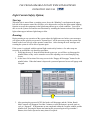
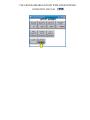
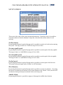
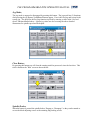
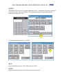
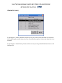
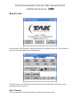
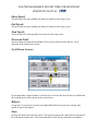
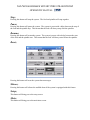
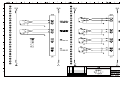
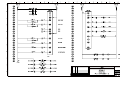
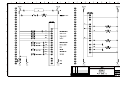
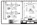
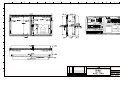
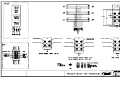
TAK PROGRAMMABLE ROTARY WIRE STRAIGHTENER
OPERATION MANUAL
Power On & Confirmation of Settings:
General – The power input point for the TAK RWS System is located in the main utility cabinet and channeled to the
operating devices and operator interface. Power necessary is 208/220 VAC 3Ph on a 20A circuit.
Upon first power up of the system the Operator Interface Screen will display any system fault messages and wait until
the faults are corrected and the operator touches the “reset” section on the touch screen.
Due to the extreme versatility of this feed system and software all instructions are written to
convey the most general operation of the system. Many options and add-on features are
available and not described or addressed in this manual but personal assistance is available
from TAK on all features or applications.
Warning - Be sure to check all settings for the current job before allowing the RWS System to
proceed with any operations! If this is a new job please see the section on entering job
parameters.
TAK PROGRAMMABLE ROTARY WIRE STRAIGHTENER
OPERATION MANUAL
SCREEN DESCRIPTIONS FOLLOW:
MAIN SCREEN:
This is the first screen visible after the system is powered up or has encountered a power
interruption. On this screen you will be able to access the remainder of the system.
The bar/text area at the bottom of the screen will display any error/alarm messages from the
system.
Starting from left to right:
1. Setup; will bring you to the screen where system operational parameters are viewed and
input.
2. Alarms; will bring you to the screen to view existing and logging of past system and
device alarm messages.
3. Run; will bring you to the screen where you will be able to run the system and monitor
the functions of the system.
Initial System Setup;
Threading up the RWS System:
1.
2.
3.
4.
5.
6.
7.
Check to be sure that the power is “on”.
From the main startup screen “Reset” all error messages & press the “setup” screen button.
Remove the plastic safety interlock cover in front of the drive rolls and unlatch the interlock safety cover
over the rotating spindles. When in the “setup” screen the safety interlock cover fault messages are not
displayed.
Move the “wire out” and “wire break” sensor arms to the open or “up” position.
Remove any remaining wire from the system by carefully pulling it out of the rotor and feed sections of the
system.
If required attach a new spool of material to the system payoff.
Proceed to thread the wire through the rotor section by hand feeding the wire and inch or so at a time.
TAK PROGRAMMABLE ROTARY WIRE STRAIGHTENER
OPERATION MANUAL
8.
9.
10.
11.
12.
13.
Continue with feeding the wire through the drive guides, between the drive rolls and on into any other
attached devices.
Once the wire is through the system, activate the drive roll clamping to “close” so that the upper drive wheel
comes down onto the wire and adjust the pressure as required.
If the wire did not “hang up” during threading then you can continue to feed it forward through the system
using the “jog” function until it is observed in a starting position for the process being performed.
All attached external devices should be cycled for operation.
Recheck the wire path all the way back to the payoff spool to ensure that the wire is free to be fed.
Rotate the “wire out” and “wire break” sensor arms down to ride on the wire.
Replace the plastic safety cover and rotor safety cover. The system is now ready to run.
TAK PROGRAMMABLE ROTARY WIRE STRAIGHTENER
OPERATION MANUAL
Light Curtain Safety Option;
Start up;
When the unit is started from a complete power down, the “Blanking” reset button on the upper
left side of the operator control box will have to be depressed to activate the light curtain learning
function to accept the equipment in the light beams and not go to a fault condition. You will be
able to see the system reset and become functional by watching the bottom section of the right rear
light column upper indicator light change to blue.
Running;
During running or any operation of the system where the light beams are broken, error messages
will appear on the operator screen and a “System Reset” will be necessary using the system reset
button on the lower left side of the operator control box. After clearing the error messages and
resetting the system it will be able to operate again.
If the system is equipped with the optional light curtain safety barriers a few other steps are
necessary to perform the wire thread up procedure.
1. Following the step #3 from the initial thread up process, you will have to disengage the
spindle brakes so they can be rotated to access the adjusting screws and clamping ring
screws.
2. At the lower left section of the setup screen is the “Engage & Disengage” button for the
spindle brakes. When the button is depressed a password protected screen will popup with
a keypad.
3. After entering the password (6742) the brakes will disengage and the “Maint, Run &
Main” buttons will disappear for either 2 minutes or after the button is pressed again to
cycle to “Engaged”. If adjustments are not completed within the 2 minute window and the
spindles lock, pressing the button and entering the password again will get another 2
minutes, this can be repeated as many times as required.
TAK PROGRAMMABLE ROTARY WIRE STRAIGHTENER
OPERATION MANUAL
TAK PROGRAMMABLE RWS OPERATION MANUAL
SETUP SCREEN:
This screen is the center of the system operational parameters. From this screen it is possible to
setup the machine to function manually or input key values that the machine needs to work
correctly.
Set line tension;
By pressing this button a keypad will popup and it is possible to set the wire back tension entering
the system. The range is from 0 to 35 in/lb in a range of 0% to 100%.
Set entry spindle speed;
By pressing this button a keypad will popup and it is possible to set the speed of the entry spindle.
The range is from 0 to 11,000 RPM in a range of 0% to 100%.
Set exit spindle speed;
By pressing this button a keypad will popup and it is possible to set the speed of the exit spindle.
The range is from 0 to 11,000 RPM in a range of 0% to 100%.
Set feed speed;
By pressing this button a keypad will popup and it is possible to set the speed of the feed unit.
The system feed speed range can be set from 0 to 100 feet/minute.
Wire Diameter;
By pressing this button a keypad will popup and it is possible to set the wire diameter. By setting
the correct wire diameter here and the correct wheel diameter in the “Maint.” Screen, the unit will
calculate the feed speed and processed total for the wire being used.
Audible Alarm;
By pressing this button it is possible to engage or disengage the audible alarm function.
TAK PROGRAMMABLE RWS OPERATION MANUAL
Jog Mode;
The jog mode is engaged or disengaged by pressing this button. The jog mode has (2) functions,
after pressing the jog button (2) additional buttons appear. First is the feed jog and second is the
system jog. The speed for the feed jog function is picked by entering a value in the “Set feed
speed” function detailed above. System jog values are also set using the above detailed
instructions for spindle speed and feed speed.
Clear Button;
By pressing this button you will clear the running total feet processed since the last clear. This
total is found on the ”Run” screen as shown below.
Spindle Brakes;
When the button is pressed the spindle brakes “Engage or Disengage” so they can be rotated to
access the block adjusting screws or the retaining ring locking screws.
TAK PROGRAMMABLE RWS OPERATION MANUAL
MAINT;
This button will access the core system maintenance screen. This button will popup a password
access screen and is only accessible by TAK or designated engineering personnel and the
password is available @ TAK.
** TAK default wheel diameter is 2.5000**
RUN;
By pressing this button you will be taken to the run screen.
MAIN;
By pressing this button you will be taken to the main intro screen.
TAK PROGRAMMABLE ROTARY WIRE STRAIGHTENER
OPERATION MANUAL
Alarm Screens;
By pressing the “Alarm” button on the main screen you will be shown the alarm screen (shown
above) showing the actual alarms since last cleared and the number of times that alarm has been
recorded.
By pressing the “Alarm History” button on this screen you can get detailed information on each
alarm posted.
TAK PROGRAMMABLE ROTARY WIRE STRAIGHTENER
OPERATION MANUAL
Run Screens;
By pressing the “Run Program” button on the main screen (shown above) you will be taken to
the run screen showing the system running status.
From this screen you will be able to monitor the operation of the RWS and change system
running parameters on the fly.
Line Tension;
This area shows the set line tension that was entered on the setup screen.
TAK PROGRAMMABLE ROTARY WIRE STRAIGHTENER
OPERATION MANUAL
Entry Speed;
This area shows the entry spindle speed that was entered on the setup screen.
Exit Speed;
This area shows the entry spindle speed that was entered on the setup screen.
Feed Speed;
This area shows the feed speed that was entered on the setup screen.
Processed Total;
This area shows the approximate number of feet of wire processed since the last “Clear”
described in the setup screen section.
Up & Down Arrows;
By pressing either of these buttons, it will increase or decrease the speed of the exit spindle and
the resulting speed will be shown on the section above.
ReSync;
At any time, if you wish to reset the exit spindle RPM back to being in sync with the entry
spindle just press this button.
Start;
Pressing this button will start the system. The system is preset with a delay between the start of
the feed and the spindle start. This means that the feed will always start before the spindles.
TAK PROGRAMMABLE ROTARY WIRE STRAIGHTENER
OPERATION MANUAL
Stop;
Pressing this button will stop the system. The feed and spindles will stop together.
Pause;
Pressing this button will pause the system. The system is preset with a delay between the stop of
the feed and the spindle stop. This means that the feed will always stop after the spindles.
Resume;
Pressing this button will restart the system. The system is preset with a delay between the start
of the feed and the spindle start. This means that the feed will always start before the spindles.
Reset;
Pressing this button will reset the system alarm messages.
Silence;
Pressing this button will silence the audible alarm if the system is equipped with this feature.
Setup;
This button will bring you to the setup screen.
Main;
This button will bring you to the main intro screen.
WARNING
The operator of the equipment offered herein must not be in or near the point-of–operation of any such machine or operating parts of any
equipment installed on a machine, or bodily injury could result. The EMPLOYER must conspicuously display adequate warning signs on
the machine with proper warnings for the machine and the specific application to which the machine and equipment are being applied.
OSHA Sections 1910.147, 1910.211, 1910.212 and 1910.217 contain installation information on the required distance between danger
points and point-of-operation guards and devices. No specific references have been made to which paragraph of OSHA 1910.147,
1910.211, 1910.211, 1910.217 or any other applicable sections because the paragraphs may change with each edition of the publications
of OSHA provisions.
All equipment manufactured by TAK Enterprises is designed to meet the construction standards of OSHA in effect at the time of sale,
however, the EMPLOYER ultimately installs the equipment and is therefore responsible for installation, use, application, training and
maintenance, as well as ensuring that adequate warning signs are visible on the machine onto which the equipment will be installed.
OSHA states that the EMPLOYER must ensure that safe operating methods designed to control or eliminate hazards to operating
personnel are developed and employed, and that operators are trained in safe operation of the equipment.
It shall be the responsibility of the EMPLOYER to establish and follow a program of periodic and regular inspections and maintenance of
machinery to insure that all their parts, auxiliary equipment and safeguards are in a safe operating condition and adjustment. Each
machine should be inspected and tested no less than weekly to determine and confirm that the operating condition of the machine meets
safety standards. Necessary maintenance or repairs to machinery, auxiliary equipment and safeguards shall be performed and completed
before the machine is operated. The EMPLOYER shall maintain accurate records of these inspections and maintenance work performed.
It is not the responsibility of TAK Enterprises to provide notification to the user of this equipment concerning future changes in State or
Federal laws, or construction standards.
SAFETY PROGRAM
Accident free operation will result from a well developed, management sponsored and enforced safety program.
Of vital importance to the success of a safety program is the proper selection of guards and devices. However, there is no safety device
that will insure “automatic” or “fool proof” safety to your operation.
Of equal importance to the proper selection of machine guards and devices is effective training of operating personnel. Each
individual must be trained in the proper operation in accordance with established standards developed for the guards or safety
devices employed, with emphasis on why specific guards and safety devices have been provided on the equipment. Rules for safe
operation should be in writing, available to company personnel and enforced at all times.
An effective safety program must include regularly scheduled inspections and maintenance of all equipment, with accurate records to
reflect the successful completion of inspections and maintenance.
To ensure that a safe working environment is maintained at all times, management, supervisors, safety engineers and all production
employees must assume their proper share of responsibility to establish and maintain an effective safety program. All members of the
company community should be involved so that an accurate view of the specific areas within the facility that require attention are
addressed.
To assist you in the development of and maintenance of an effective safety program, many trade groups and safety related organizations
provide guidelines and recommendations that are available to you. However, you must know when and how to apply these guidelines.
The equipment manufacturers provide information to assist you in properly adjusting and maintaining your equipment. It is recommended
that the employer comply with these guidelines at all times.
1|Page
30 April 2008
MATERIAL REQ'D.
STACK
J5
SONIC
(BLUE)
RED
(RED)
J3
1
1
2
2
3
3
4
4
5
5
1
1
2
2
3
3
4
4
5
5
R.C.
2.13 [54.0]
J6
1.06 [27.0]
CLEARANCE HOLE
FOR #6 OR 4MM SCREW
J4
6
5
YELLOW LED:
OUTPUT ON
1.06 [27.0]
4.41 [111.9]
AMBER
4
3
GREEN LED:
(BLACK)
J1
1
1
2
2
3
3
4
4
5
5
POWER ON
3.94 [100.0]
J2
2
1
REMOVABLE LABELS
GREEN
(GREEN)
0.24 [6.0]
1.299 [33.0]
V-
GREEN
GREY
RED
BLUE
GND
V+
GRN/YEL
BROWN
PINK
1
WHITE
2
YELLOW
GREEN
4
RED
BLACK
-24
BLUE
WHITE
C
3
LOOP START (3/4)
SYSTEM ERROR
(3/4)
JOG (1/3/4)
24VDC SYSTEM ERROR
SPARE INPUT (1/3/4)
FEED ROLL GRIP (1/3/4)
OUTPUT SIGNAL (3/4)
3
4
REMOTE START (3/4)
OIT
5
REMOTE STOP (3/4)
1
6
LOOP START (1/3/4)
2
LOOP STOP (1/3/4)
3
ROTOR SAFETY COVER (1/3/4)
4
3
REMOTE STOP (1/3/4)
1
WIRE BREAK (1/3/4)
4
REMOTE START (1/3/4)
6
5
2
WIRE OUT (1/3/4)
FEED SAFETY COVER (1/3/4)
2
1
GND
SCREEN GND
SCREEN V+
1
BLUE V+
E-STOP BK
2
PURPLE
E-STOP BK
3
RED
SCREEN V-
4
WHITE V-
5
BLACK
24VDC SIGNAL INPUT (JB-3)
(JB-2) REMOTE INPUT PORTS (1-5)
(JB-2) REMOTE OUTPUT PORT
MAIN INPUT (JB-1)
(6)
INPUT PIN #1- POSITIVE/BROWN
EuroFast
INPUT PIN #2- N/A
Female Pins,
Female Threads
INPUT PIN #3- GROUND/BLUE
or Coupling Nut
INPUT PIN #4- SIGNAL/BLACK
5-pin
INPUT PIN #5- SPARE
GDH
A
REV
TOLERANCE UNLESS
OTHERWISE STATED
3
PRECISION ROTARY WIRE STRAIGHTENER
FRACT +/- 1/16
0.0003
.X
.032
0.0002
.XX
.015
0.0005
.XXX
.005
0.0005
.XXXX
.0005
CHG BY
112508
DATE
DRAWING / PART NO.
CAD
DWN
ECN
GDH
CHK
SCALE
DATE 102907
9111-601
PART NAME
TABLETOP I/O BLOCK
CONNECTIONS
CUSTOMER
TAK