1
STM8S20xxx
Performance line, 24 MHz STM8S 8-bit MCU, up to 128 Kbytes Flash,
integrated EEPROM,10-bit ADC, timers, 2 UARTs, SPI, I²C, CAN
Features
Core
■
Max fCPU: up to 24 MHz,
0 wait states @ fCPU≤16 MHz
■ Advanced STM8 core with Harvard
architecture and 3-stage pipeline
■ Extended instruction set
■
■
Program memory: Up to 128 Kbytes Flash;
data retention 20 years at 55°C after 10 kcycles
■ Data memory: Up to 2 Kbytes true data
EEPROM; endurance 300 kcycles
■ RAM: Up to 6 Kbytes
Clock, reset and supply management
2.95 to 5.5 V operating voltage
■
Flexible clock control, 4 master clock sources:
– Low power crystal resonator oscillator
– External clock input
– Internal, user-trimmable 16 MHz RC
– Internal low power 128 kHz RC
■ Clock security system with clock monitor
■ Power management:
– Low power modes (Wait, Active-halt, Halt)
– Switch-off peripheral clocks individually
■ Permanently active, low consumption poweron and power-down reset
Interrupt management
■
Nested interrupt controller with 32 interrupts
■ Up to 37 external interrupts on 6 vectors
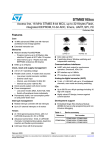
LQFP48 7x7
■
■
Communications interfaces
■
■
■
■
■
High speed 1 Mbit/s active CAN 2.0B interface
UART with clock output for synchronous
operation - LIN master mode
UART with LIN 2.1 compliant, master/slave
modes and automatic resynchronization
SPI interface up to 10 Mbit/s
I2C interface up to 400 Kbit/s
Analog to digital converter (ADC)
■
10-bit ADC with up to 16 channels
I/Os
■
Up to 68 I/Os on an 80-pin package including
18 high sink outputs
■ Highly robust I/O design, immune against
current injection
■
Development support
– Single Wire Interface Module (SWIM) and
Debug Module (DM) for fast on-chip
programming and non-intrusive debugging
Table 1.
Device summary
Reference
2x 16-bit general purpose timers, with 2+3
CAPCOM channels (IC, OC or PWM)
■ Advanced control timer: 16-bit, 4 CAPCOM
channels, 3 complementary outputs, dead-time
insertion and flexible synchronization
■ 8-bit basic timer with 8-bit prescaler
January 2009
LQFP32 7x7
Auto wakeup timer
Window watchdog and independent watchdog
Timers
■
LQFP44 10x10
LQFP80 14x14
Max. 20 MIPS @ 24 MHz
Memories
■
LQFP64 10x10
Part number
STM8S207xx
STM8S207MB, STM8S207RB,
STM8S207R8, STM8S207R6,
STM8S207CB, STM8S207C6,
STM8S207C8, STM8S207S6,
STM8S207S8, STM8S207K6
STM8S208xx
STM8S208MB, STM8S208RB
Rev 7
1/96
www.st.com
1
Contents
STM8S20xxx
Contents
1
Introduction . . . . . . . . . . . . . . . . . . . . . . . . . . . . . . . . . . . . . . . . . . . . . . . . 8
2
Description . . . . . . . . . . . . . . . . . . . . . . . . . . . . . . . . . . . . . . . . . . . . . . . . . 9
3
Block diagram . . . . . . . . . . . . . . . . . . . . . . . . . . . . . . . . . . . . . . . . . . . . . 10
4
Product overview . . . . . . . . . . . . . . . . . . . . . . . . . . . . . . . . . . . . . . . . . . 11
5
4.1
Central processing unit STM8 . . . . . . . . . . . . . . . . . . . . . . . . . . . . . . . . . 11
4.2
Single wire interface module (SWIM) and debug module (DM) . . . . . . . . 12
4.3
Interrupt controller . . . . . . . . . . . . . . . . . . . . . . . . . . . . . . . . . . . . . . . . . . 12
4.4
Flash program and data EEPROM memory . . . . . . . . . . . . . . . . . . . . . . . 13
4.5
Clock controller . . . . . . . . . . . . . . . . . . . . . . . . . . . . . . . . . . . . . . . . . . . . . 14
4.6
Power management . . . . . . . . . . . . . . . . . . . . . . . . . . . . . . . . . . . . . . . . . 14
4.7
Watchdog timers . . . . . . . . . . . . . . . . . . . . . . . . . . . . . . . . . . . . . . . . . . . 15
4.8
Auto wakeup counter . . . . . . . . . . . . . . . . . . . . . . . . . . . . . . . . . . . . . . . . 15
4.9
Beeper . . . . . . . . . . . . . . . . . . . . . . . . . . . . . . . . . . . . . . . . . . . . . . . . . . . 16
4.10
TIM1 - 16-bit advanced control timer . . . . . . . . . . . . . . . . . . . . . . . . . . . . 16
4.11
TIM2, TIM3 - 16-bit general purpose timers . . . . . . . . . . . . . . . . . . . . . . . 16
4.12
TIM4 - 8-bit basic timer . . . . . . . . . . . . . . . . . . . . . . . . . . . . . . . . . . . . . . . 16
4.13
Analog/digital converter (ADC2) . . . . . . . . . . . . . . . . . . . . . . . . . . . . . . . . 17
4.14
Communication interfaces . . . . . . . . . . . . . . . . . . . . . . . . . . . . . . . . . . . . 17
4.14.1
UART1 . . . . . . . . . . . . . . . . . . . . . . . . . . . . . . . . . . . . . . . . . . . . . . . . . . 17
4.14.2
UART3 . . . . . . . . . . . . . . . . . . . . . . . . . . . . . . . . . . . . . . . . . . . . . . . . . . 18
4.14.3
SPI . . . . . . . . . . . . . . . . . . . . . . . . . . . . . . . . . . . . . . . . . . . . . . . . . . . . . 19
4.14.4
I2C . . . . . . . . . . . . . . . . . . . . . . . . . . . . . . . . . . . . . . . . . . . . . . . . . . . . . 19
4.14.5
CAN . . . . . . . . . . . . . . . . . . . . . . . . . . . . . . . . . . . . . . . . . . . . . . . . . . . . 19
Pinouts and pin description . . . . . . . . . . . . . . . . . . . . . . . . . . . . . . . . . . 21
5.1
Package pinouts . . . . . . . . . . . . . . . . . . . . . . . . . . . . . . . . . . . . . . . . . . . . 21
5.1.1
6
2/96
Alternate function remapping . . . . . . . . . . . . . . . . . . . . . . . . . . . . . . . . . 31
Option bytes . . . . . . . . . . . . . . . . . . . . . . . . . . . . . . . . . . . . . . . . . . . . . . 32
STM8S20xxx
7
Memory map . . . . . . . . . . . . . . . . . . . . . . . . . . . . . . . . . . . . . . . . . . . . . . 35
7.1
8
Register map . . . . . . . . . . . . . . . . . . . . . . . . . . . . . . . . . . . . . . . . . . . . . . 36
Electrical characteristics . . . . . . . . . . . . . . . . . . . . . . . . . . . . . . . . . . . . 49
8.1
Parameter conditions . . . . . . . . . . . . . . . . . . . . . . . . . . . . . . . . . . . . . . . . 49
8.1.1
Minimum and maximum values . . . . . . . . . . . . . . . . . . . . . . . . . . . . . . . 49
8.1.2
Typical values . . . . . . . . . . . . . . . . . . . . . . . . . . . . . . . . . . . . . . . . . . . . . 49
8.1.3
Typical curves . . . . . . . . . . . . . . . . . . . . . . . . . . . . . . . . . . . . . . . . . . . . 49
8.1.4
Typical current consumption . . . . . . . . . . . . . . . . . . . . . . . . . . . . . . . . . 49
8.1.5
Pin loading conditions . . . . . . . . . . . . . . . . . . . . . . . . . . . . . . . . . . . . . . 50
8.1.6
Loading capacitor . . . . . . . . . . . . . . . . . . . . . . . . . . . . . . . . . . . . . . . . . 50
8.1.7
Pin input voltage . . . . . . . . . . . . . . . . . . . . . . . . . . . . . . . . . . . . . . . . . . 50
8.2
Absolute maximum ratings . . . . . . . . . . . . . . . . . . . . . . . . . . . . . . . . . . . . 51
8.3
Operating conditions . . . . . . . . . . . . . . . . . . . . . . . . . . . . . . . . . . . . . . . . 53
8.4
9
Contents
8.3.1
VCAP external capacitor . . . . . . . . . . . . . . . . . . . . . . . . . . . . . . . . . . . . 54
8.3.2
Supply current characteristics . . . . . . . . . . . . . . . . . . . . . . . . . . . . . . . . 55
8.3.3
External clock sources and timing characteristics . . . . . . . . . . . . . . . . . 62
8.3.4
Internal clock sources and timing characteristics . . . . . . . . . . . . . . . . . 64
8.3.5
Memory characteristics . . . . . . . . . . . . . . . . . . . . . . . . . . . . . . . . . . . . . 66
8.3.6
I/O port pin characteristics . . . . . . . . . . . . . . . . . . . . . . . . . . . . . . . . . . . 67
8.3.7
Reset pin characteristics . . . . . . . . . . . . . . . . . . . . . . . . . . . . . . . . . . . . 72
8.3.8
SPI serial peripheral interface . . . . . . . . . . . . . . . . . . . . . . . . . . . . . . . . 74
8.3.9
I2C interface characteristics . . . . . . . . . . . . . . . . . . . . . . . . . . . . . . . . . . 77
8.3.10
10-bit ADC characteristics . . . . . . . . . . . . . . . . . . . . . . . . . . . . . . . . . . . 78
8.3.11
EMC characteristics . . . . . . . . . . . . . . . . . . . . . . . . . . . . . . . . . . . . . . . . 81
Thermal characteristics . . . . . . . . . . . . . . . . . . . . . . . . . . . . . . . . . . . . . . 84
8.4.1
Reference document . . . . . . . . . . . . . . . . . . . . . . . . . . . . . . . . . . . . . . . 84
8.4.2
Selecting the product temperature range . . . . . . . . . . . . . . . . . . . . . . . . 85
Package characteristics . . . . . . . . . . . . . . . . . . . . . . . . . . . . . . . . . . . . . 86
9.1
Package mechanical data . . . . . . . . . . . . . . . . . . . . . . . . . . . . . . . . . . . . 87
9.1.1
10
LQFP package mechanical data . . . . . . . . . . . . . . . . . . . . . . . . . . . . . . 87
STM8 development tools . . . . . . . . . . . . . . . . . . . . . . . . . . . . . . . . . . . . 92
10.1
Emulation and in-circuit debugging tools . . . . . . . . . . . . . . . . . . . . . . . . . 92
10.2
Software tools . . . . . . . . . . . . . . . . . . . . . . . . . . . . . . . . . . . . . . . . . . . . . . 93
3/96
Contents
STM8S20xxx
10.3
10.2.1
STM8 toolset . . . . . . . . . . . . . . . . . . . . . . . . . . . . . . . . . . . . . . . . . . . . . 93
10.2.2
C and assembly toolchains . . . . . . . . . . . . . . . . . . . . . . . . . . . . . . . . . . 93
Programming tools . . . . . . . . . . . . . . . . . . . . . . . . . . . . . . . . . . . . . . . . . . 93
11
Ordering information . . . . . . . . . . . . . . . . . . . . . . . . . . . . . . . . . . . . . . . 94
12
Revision history . . . . . . . . . . . . . . . . . . . . . . . . . . . . . . . . . . . . . . . . . . . 95
4/96
STM8S20xxx
List of tables
List of tables
Table 1.
Table 2.
Table 3.
Table 4.
Table 5.
Table 6.
Table 7.
Table 8.
Table 9.
Table 10.
Table 11.
Table 12.
Table 13.
Table 14.
Table 15.
Table 16.
Table 17.
Table 18.
Table 19.
Table 20.
Table 21.
Table 22.
Table 23.
Table 24.
Table 25.
Table 26.
Table 27.
Table 28.
Table 29.
Table 30.
Table 31.
Table 32.
Table 33.
Table 34.
Table 35.
Table 36.
Table 37.
Table 38.
Table 39.
Table 40.
Table 41.
Table 42.
Table 43.
Table 44.
Table 45.
Table 46.
Table 47.
Table 48.
Device summary . . . . . . . . . . . . . . . . . . . . . . . . . . . . . . . . . . . . . . . . . . . . . . . . . . . . . . . . . . 1
STM8S20xxx performance line features. . . . . . . . . . . . . . . . . . . . . . . . . . . . . . . . . . . . . . . . 9
TIM timer features. . . . . . . . . . . . . . . . . . . . . . . . . . . . . . . . . . . . . . . . . . . . . . . . . . . . . . . . 16
Legend/abbreviations . . . . . . . . . . . . . . . . . . . . . . . . . . . . . . . . . . . . . . . . . . . . . . . . . . . . . 26
Pin description . . . . . . . . . . . . . . . . . . . . . . . . . . . . . . . . . . . . . . . . . . . . . . . . . . . . . . . . . . 26
Option bytes . . . . . . . . . . . . . . . . . . . . . . . . . . . . . . . . . . . . . . . . . . . . . . . . . . . . . . . . . . . . 32
Option byte description . . . . . . . . . . . . . . . . . . . . . . . . . . . . . . . . . . . . . . . . . . . . . . . . . . . . 33
Flash, Data EEPROM and RAM boundary addresses . . . . . . . . . . . . . . . . . . . . . . . . . . . . 36
I/O port hardware register map . . . . . . . . . . . . . . . . . . . . . . . . . . . . . . . . . . . . . . . . . . . . . . 36
General hardware register map . . . . . . . . . . . . . . . . . . . . . . . . . . . . . . . . . . . . . . . . . . . . . 38
CPU/SWIM/debug module/interrupt controller registers . . . . . . . . . . . . . . . . . . . . . . . . . . . 47
Voltage characteristics . . . . . . . . . . . . . . . . . . . . . . . . . . . . . . . . . . . . . . . . . . . . . . . . . . . . 51
Current characteristics . . . . . . . . . . . . . . . . . . . . . . . . . . . . . . . . . . . . . . . . . . . . . . . . . . . . 52
Thermal characteristics. . . . . . . . . . . . . . . . . . . . . . . . . . . . . . . . . . . . . . . . . . . . . . . . . . . . 52
General operating conditions . . . . . . . . . . . . . . . . . . . . . . . . . . . . . . . . . . . . . . . . . . . . . . . 53
Operating conditions at power-up/power-down . . . . . . . . . . . . . . . . . . . . . . . . . . . . . . . . . 54
Total current consumption with code execution in run mode at VDD = 5.0 V . . . . . . . . . . . 55
Total current consumption with code execution in run mode at VDD = 3.3 V . . . . . . . . . . . 56
Total current consumption in Wait mode at VDD = 5.0 V . . . . . . . . . . . . . . . . . . . . . . . . . . 57
Total current consumption in Wait mode at VDD = 3.3 V . . . . . . . . . . . . . . . . . . . . . . . . . . 57
Total current consumption in active halt mode at VDD = 5.0 V, TA -40 to 85° C . . . . . . . . . 58
Total current consumption in active halt mode at VDD = 3.3 V . . . . . . . . . . . . . . . . . . . . . . 58
Total current consumption in halt mode at VDD = 5.0 V, TA -40 to 85° C . . . . . . . . . . . . . . 59
Total current consumption in halt mode at VDD = 3.3 V . . . . . . . . . . . . . . . . . . . . . . . . . . . 59
Wakeup times . . . . . . . . . . . . . . . . . . . . . . . . . . . . . . . . . . . . . . . . . . . . . . . . . . . . . . . . . . . 60
Total current consumption and timing in forced reset state . . . . . . . . . . . . . . . . . . . . . . . . 60
Peripheral current consumption . . . . . . . . . . . . . . . . . . . . . . . . . . . . . . . . . . . . . . . . . . . . . 61
HSE user external clock characteristics . . . . . . . . . . . . . . . . . . . . . . . . . . . . . . . . . . . . . . . 62
HSE oscillator characteristics . . . . . . . . . . . . . . . . . . . . . . . . . . . . . . . . . . . . . . . . . . . . . . . 63
HSI oscillator characteristics. . . . . . . . . . . . . . . . . . . . . . . . . . . . . . . . . . . . . . . . . . . . . . . . 64
LSI oscillator characteristics . . . . . . . . . . . . . . . . . . . . . . . . . . . . . . . . . . . . . . . . . . . . . . . . 65
RAM and hardware registers . . . . . . . . . . . . . . . . . . . . . . . . . . . . . . . . . . . . . . . . . . . . . . . 66
Flash program memory/data EEPROM memory . . . . . . . . . . . . . . . . . . . . . . . . . . . . . . . . 66
I/O static characteristics . . . . . . . . . . . . . . . . . . . . . . . . . . . . . . . . . . . . . . . . . . . . . . . . . . . 67
Output driving current (standard ports) . . . . . . . . . . . . . . . . . . . . . . . . . . . . . . . . . . . . . . . . 69
Output driving current (true open drain ports). . . . . . . . . . . . . . . . . . . . . . . . . . . . . . . . . . . 69
Output driving current (high sink ports). . . . . . . . . . . . . . . . . . . . . . . . . . . . . . . . . . . . . . . . 69
NRST pin characteristics . . . . . . . . . . . . . . . . . . . . . . . . . . . . . . . . . . . . . . . . . . . . . . . . . . 72
SPI characteristics . . . . . . . . . . . . . . . . . . . . . . . . . . . . . . . . . . . . . . . . . . . . . . . . . . . . . . . 74
I2C characteristics. . . . . . . . . . . . . . . . . . . . . . . . . . . . . . . . . . . . . . . . . . . . . . . . . . . . . . . . 77
ADC characteristics . . . . . . . . . . . . . . . . . . . . . . . . . . . . . . . . . . . . . . . . . . . . . . . . . . . . . . 78
ADC accuracy with RAIN < 10 kΩ RAIN, VDDA = 3.3 V. . . . . . . . . . . . . . . . . . . . . . . . . . . . . 79
ADC accuracy with RAIN < 10 kΩ , VDDA = 5 V. . . . . . . . . . . . . . . . . . . . . . . . . . . . . . . . . . 79
EMS data . . . . . . . . . . . . . . . . . . . . . . . . . . . . . . . . . . . . . . . . . . . . . . . . . . . . . . . . . . . . . . 82
EMI data . . . . . . . . . . . . . . . . . . . . . . . . . . . . . . . . . . . . . . . . . . . . . . . . . . . . . . . . . . . . . . . 82
ESD absolute maximum ratings . . . . . . . . . . . . . . . . . . . . . . . . . . . . . . . . . . . . . . . . . . . . . 83
Electrical sensitivities . . . . . . . . . . . . . . . . . . . . . . . . . . . . . . . . . . . . . . . . . . . . . . . . . . . . . 83
Thermal characteristics. . . . . . . . . . . . . . . . . . . . . . . . . . . . . . . . . . . . . . . . . . . . . . . . . . . . 84
5/96
List of tables
Table 49.
Table 50.
Table 51.
Table 52.
Table 53.
Table 54.
Table 55.
6/96
STM8S20xxx
Junction temperature range . . . . . . . . . . . . . . . . . . . . . . . . . . . . . . . . . . . . . . . . . . . . . . . . 85
80-pin low profile quad flat package mechanical data . . . . . . . . . . . . . . . . . . . . . . . . . . . . 87
64-pin low profile quad flat package mechanical data (10 x 10) . . . . . . . . . . . . . . . . . . . . . 88
48-pin low profile quad flat package mechanical data . . . . . . . . . . . . . . . . . . . . . . . . . . . . 89
44-pin low profile quad flat package mechanical data . . . . . . . . . . . . . . . . . . . . . . . . . . . . 90
32-pin low profile quad flat package mechanical data . . . . . . . . . . . . . . . . . . . . . . . . . . . . 91
Document revision history . . . . . . . . . . . . . . . . . . . . . . . . . . . . . . . . . . . . . . . . . . . . . . . . . 95
STM8S20xxx
List of figures
List of figures
Figure 1.
Figure 2.
Figure 3.
Figure 4.
Figure 5.
Figure 6.
Figure 7.
Figure 8.
Figure 9.
Figure 10.
Figure 11.
Figure 12.
Figure 13.
Figure 14.
Figure 15.
Figure 16.
Figure 17.
Figure 18.
Figure 19.
Figure 20.
Figure 21.
Figure 22.
Figure 23.
Figure 24.
Figure 25.
Figure 26.
Figure 27.
Figure 28.
Figure 29.
Figure 30.
Figure 31.
Figure 32.
Figure 33.
Figure 34.
Figure 35.
Figure 36.
Figure 37.
Figure 38.
Figure 39.
Figure 40.
Figure 41.
Figure 42.
Figure 43.
Figure 44.
Figure 45.
Figure 46.
Figure 47.
STM8S20xxx performance line block diagram . . . . . . . . . . . . . . . . . . . . . . . . . . . . . . . . . 10
Flash memory organization . . . . . . . . . . . . . . . . . . . . . . . . . . . . . . . . . . . . . . . . . . . . . . . . 13
LQFP 80-pin pinout. . . . . . . . . . . . . . . . . . . . . . . . . . . . . . . . . . . . . . . . . . . . . . . . . . . . . . . 21
LQFP 64-pin pinout. . . . . . . . . . . . . . . . . . . . . . . . . . . . . . . . . . . . . . . . . . . . . . . . . . . . . . . 22
LQFP 48-pin pinout. . . . . . . . . . . . . . . . . . . . . . . . . . . . . . . . . . . . . . . . . . . . . . . . . . . . . . . 23
LQFP 44-pin pinout. . . . . . . . . . . . . . . . . . . . . . . . . . . . . . . . . . . . . . . . . . . . . . . . . . . . . . . 24
LQFP 32-pin pinout . . . . . . . . . . . . . . . . . . . . . . . . . . . . . . . . . . . . . . . . . . . . . . . . . . . . . . 25
Memory map . . . . . . . . . . . . . . . . . . . . . . . . . . . . . . . . . . . . . . . . . . . . . . . . . . . . . . . . . . . . 35
Supply current measurement conditions . . . . . . . . . . . . . . . . . . . . . . . . . . . . . . . . . . . . . . 49
Pin loading conditions . . . . . . . . . . . . . . . . . . . . . . . . . . . . . . . . . . . . . . . . . . . . . . . . . . . . . 50
Pin input voltage . . . . . . . . . . . . . . . . . . . . . . . . . . . . . . . . . . . . . . . . . . . . . . . . . . . . . . . . . 50
fCPUmax Versus VDD . . . . . . . . . . . . . . . . . . . . . . . . . . . . . . . . . . . . . . . . . . . . . . . . . . . . . . . . . . . . . . . . . . . . 53
External capacitor . . . . . . . . . . . . . . . . . . . . . . . . . . . . . . . . . . . . . . . . . . . . . . . . . . . . . . . . 54
Typ. IDD(RUN) vs. VDD, HSI RC osc, fCPU = 16 MHz . . . . . . . . . . . . . . . . . . . . . . . . . . . . . 61
Typ. IDD(WFI) vs. VDD, HSI RC osc, fCPU = 16 MHz. . . . . . . . . . . . . . . . . . . . . . . . . . . . . . 61
HSE external clock source . . . . . . . . . . . . . . . . . . . . . . . . . . . . . . . . . . . . . . . . . . . . . . . . . 62
HSE oscillator circuit diagram . . . . . . . . . . . . . . . . . . . . . . . . . . . . . . . . . . . . . . . . . . . . . . . 63
Typical HSI frequency vs VDD @ 4 temperatures. . . . . . . . . . . . . . . . . . . . . . . . . . . . . . . . 64
Typical LSI frequency vs VDD . . . . . . . . . . . . . . . . . . . . . . . . . . . . . . . . . . . . . . . . . . . . . . 65
Typical VIL and VIH vs VDD @ 4 temperatures . . . . . . . . . . . . . . . . . . . . . . . . . . . . . . . . . . 68
Typical pull-up resistance RPU vs VDD @ 4 temperatures . . . . . . . . . . . . . . . . . . . . . . . . . 68
Typical pull-up current Ipu vs VDD @ 4 temperatures . . . . . . . . . . . . . . . . . . . . . . . . . . . . . 68
Typ. VOL @ VDD = 3.3 V (standard ports). . . . . . . . . . . . . . . . . . . . . . . . . . . . . . . . . . . . . 70
Typ. VOL @ VDD = 5.0 V (standard ports). . . . . . . . . . . . . . . . . . . . . . . . . . . . . . . . . . . . . 70
Typ. VOL @ VDD = 3.3 V (true open drain ports) . . . . . . . . . . . . . . . . . . . . . . . . . . . . . . . 70
Typ. VOL @ VDD = 5.0 V (true open drain ports) . . . . . . . . . . . . . . . . . . . . . . . . . . . . . . . 70
Typ. VOL @ VDD = 3.3 V (high sink ports) . . . . . . . . . . . . . . . . . . . . . . . . . . . . . . . . . . . . 70
Typ. VOL @ VDD = 5.0 V (high sink ports) . . . . . . . . . . . . . . . . . . . . . . . . . . . . . . . . . . . . 70
Typ. VDD - VOH @ VDD = 3.3 V (standard ports) . . . . . . . . . . . . . . . . . . . . . . . . . . . . . . . 71
Typ. VDD - VOH @ VDD = 5.0 V (standard ports) . . . . . . . . . . . . . . . . . . . . . . . . . . . . . . . 71
Typ. VDD - VOH @ VDD = 3.3 V (high sink ports) . . . . . . . . . . . . . . . . . . . . . . . . . . . . . . . 71
Typ. VDD - VOH @ VDD = 5.0 V (high sink ports) . . . . . . . . . . . . . . . . . . . . . . . . . . . . . . . 71
Typical NRST VIL and VIH vs VDD @ 4 temperatures. . . . . . . . . . . . . . . . . . . . . . . . . . . . . 72
Typical NRST pull-up resistance RPU vs VDD @ 4 temperatures . . . . . . . . . . . . . . . . . . . . 73
Typical NRST pull-up current Ipu vs VDD @ 4 temperatures . . . . . . . . . . . . . . . . . . . . . . . 73
Recommended reset pin protection . . . . . . . . . . . . . . . . . . . . . . . . . . . . . . . . . . . . . . . . . . 73
SPI timing diagram - slave mode and CPHA=0 . . . . . . . . . . . . . . . . . . . . . . . . . . . . . . . . . 75
SPI timing diagram - slave mode and CPHA=1(1) . . . . . . . . . . . . . . . . . . . . . . . . . . . . . . . 75
SPI timing diagram - master mode(1) . . . . . . . . . . . . . . . . . . . . . . . . . . . . . . . . . . . . . . . . . 76
ADC accuracy characteristics . . . . . . . . . . . . . . . . . . . . . . . . . . . . . . . . . . . . . . . . . . . . . . . 80
Typical application with ADC . . . . . . . . . . . . . . . . . . . . . . . . . . . . . . . . . . . . . . . . . . . . . . . 80
80-pin low profile quad flat package (14 x 14) . . . . . . . . . . . . . . . . . . . . . . . . . . . . . . . . . . 87
64-pin low profile quad flat package (10 x 10) . . . . . . . . . . . . . . . . . . . . . . . . . . . . . . . . . . 88
48-pin low profile quad flat package (7 x 7) . . . . . . . . . . . . . . . . . . . . . . . . . . . . . . . . . . . . 89
44-pin low profile quad flat package (10 x 10) . . . . . . . . . . . . . . . . . . . . . . . . . . . . . . . . . . 90
32-pin low profile quad flat package (7 x 7) . . . . . . . . . . . . . . . . . . . . . . . . . . . . . . . . . . . . 91
STM8S207/208xx performance line ordering information scheme . . . . . . . . . . . . . . . . . . . 94
7/96
Introduction
1
STM8S20xxx
Introduction
This datasheet contains the description of the STM8S20xxx performance line features,
pinout, electrical characteristics, mechanical data and ordering information.
8/96
●
For complete information on the STM8S microcontroller memory, registers and
peripherals, please refer to the STM8S microcontroller family reference manual
(RM0016).
●
For information on programming, erasing and protection of the internal Flash memory
please refer to the STM8S Flash programming manual (PM0051).
●
For information on the debug and SWIM (single wire interface module) refer to the
STM8 SWIM communication protocol and debug module user manual (UM0470).
●
For information on the STM8 core, please refer to the STM8 CPU programming manual
(PM0044).
STM8S20xxx
2
Description
Description
The STM8S20xxx performance line 8-bit microcontrollers offer high density (from 32 to
128 Kbytes) Flash program memory.
All devices of the STM8S20xxx performance line provide the following benefits:
●
●
●
●
–
Integrated true data EEPROM for up to 300 k write/erase cycles
–
High system integration level with internal clock oscillators, watchdog and brownout reset
Performance and robustness
–
20 MIPS at 24 MHz CPU clock frequency
–
Robust I/O, independent watchdogs with separate clock source
–
Clock security system
Short development cycles
–
Applications scalability across a common family product architecture with
compatible pinout, memory map and and modular peripherals.
–
Full documentation and a wide choice of development tools
Product longevity
–
Advanced core and peripherals made in a state-of-the art technology
–
A family of products for applications with 2.95 to 5.5 V operating supply
No. of maximum GPIO
(I/O)
Ext. Interrupt pins
Timer CAPCOM channels
Timer PWM channels(1)
A/D Converter channels
High sink I/Os
High density
Flash Program memory
(bytes)
Data EEPROM (bytes)
RAM (bytes)
beCAN interface
STM8S20xxx performance line features
Pin count
Table 2.
Reduced system cost
STM8S207MB
STM8S207RB
STM8S207R8
STM8S207R6
STM8S207CB
STM8S207C8
STM8S207S8
STM8S207C6
STM8S207S6
STM8S207K6
80
64
64
64
48
48
44
48
44
32
68
52
52
52
38
38
34
38
34
25
37
36
36
36
35
35
31
35
31
23
9
9
9
9
9
9
8
9
8
8
12
12
12
12
12
12
11
12
11
11
16
16
16
16
10
10
9
10
9
7
18
16
16
16
16
16
15
16
15
12
128K
128K
64K
32K
128K
64K
64K
32K
32K
32K
2048
2048
1536
1024
2048
1536
1536
1024
1024
1024
6K
6K
4K
2K
6K
4K
4K
2K
2K
2K
-
STM8S208MB
STM8S208RB
80
64
68
52
37
37
9
9
12
12
16
16
18
16
128K
128K
2048
2048
6K
6K
Yes
Device
1. Including complementary outputs.
9/96
Block diagram
3
STM8S20xxx
Block diagram
Figure 1.
STM8S20xxx performance line block diagram
Reset block
XTAL 1-24 MHz
Clock controller
Reset
Reset
RC int. 16 MHz
Detector
POR
BOR
RC int. 128 kHz
Clock to peripherals and core
Window WDG
STM8 CORE
Independent WDG
400 Kbit/s
I2C
10 Mbit/s
SPI
Up to 2 Kbytes
data EEPROM
Up to 6 Kbytes
RAM
Boot ROM
LIN master
SPI emul.
UART1
Master/slave
autosynchro
UART3
16-bit advanced control
timer (TIM1)
1 Mbit/s
beCAN
16-bit general purpose
timers (TIM2, TIM3)
16 channels
1/2/4 kHz
beep
10/96
Up to 128 Kbytes
high density program
Flash
Debug/SWIM
Address and data bus
Single wire
debug interf.
ADC2
8-bit basic timer
(TIM4)
Beeper
AWU timer
Up to
9 CAPCOM
channels
STM8S20xxx
4
Product overview
Product overview
The following section intends to give an overview of the basic features of the STM8S20xxx
performance line functional modules and peripherals.
For more detailed information please refer to the corresponding family reference manual
(RM0016).
4.1
Central processing unit STM8
The 8-bit STM8 core is designed for code efficiency and performance.
It contains 6 internal registers which are directly addressable in each execution context, 20
addressing modes including indexed indirect and relative addressing and 80 instructions.
Architecture and registers
●
Harvard architecture
●
3-stage pipeline
●
32-bit wide program memory bus - single cycle fetching for most instructions
●
X and Y 16-bit index registers - enabling indexed addressing modes with or without
offset and read-modify-write type data manipulations
●
8-bit accumulator
●
24-bit program counter - 16-Mbyte linear memory space
●
16-bit stack pointer - access to a 64 K-level stack
●
8-bit condition code register - 7 condition flags for the result of the last instruction
Addressing
●
20 addressing modes
●
Indexed indirect addressing mode for look-up tables located anywhere in the address
space
●
Stack pointer relative addressing mode for local variables and parameter passing
Instruction set
●
80 instructions with 2-byte average instruction size
●
Standard data movement and logic/arithmetic functions
●
8-bit by 8-bit multiplication
●
16-bit by 8-bit and 16-bit by 16-bit division
●
Bit manipulation
●
Data transfer between stack and accumulator (push/pop) with direct stack access
●
Data transfer using the X and Y registers or direct memory-to-memory transfers
11/96
Product overview
4.2
STM8S20xxx
Single wire interface module (SWIM) and debug module (DM)
The single wire interface module and debug module permits non-intrusive, real-time incircuit debugging and fast memory programming.
SWIM
Single wire interface module for direct access to the debug module and memory
programming. The interface can be activated in all device operation modes. The maximum
data transmission speed is 145 bytes/ms.
Debug module
The non-intrusive debugging module features a performance close to a full-featured
emulator. Beside memory and peripherals, also CPU operation can be monitored in realtime by means of shadow registers.
4.3
12/96
●
R/W to RAM and peripheral registers in real-time
●
R/W access to all resources by stalling the CPU
●
Breakpoints on all program-memory instructions (software breakpoints)
●
2 advanced breakpoints, 23 predefined configurations
Interrupt controller
●
Nested interrupts with 3 software priority levels
●
32 interrupt vectors with hardware priority
●
Up to 37 external interrupts on 6 vectors including TLI
●
Trap and reset interrupts
STM8S20xxx
4.4
Product overview
Flash program and data EEPROM memory
●
Up to 128 Kbytes of high density Flash program single voltage Flash memory
●
Up to 2 K bytes true data EEPROM
●
Read while write: Writing in data memory possible while executing code in program
memory
●
User option byte area
Write protection (WP)
Write protection of Flash program memory and data EEPROM is provided to avoid
unintentional overwriting of memory that could result from a user software malfunction.
There are two levels of write protection. The first level is known as MASS (Memory Access
Security System). MASS is always enabled and protects the main Flash program memory,
data EEPROM and option bytes.
To perform In-Application Programming (IAP), this write protection can be removed by
writing a MASS key sequence in a control register. This allows the application to write to
data EEPROM, modify the contents of main program memory or the device option bytes.
A second level of write protection, can be enabled to further protect a specific area of
memory known as UBC (user boot code). Refer to Figure 2
The size of the UBC is programmable through the UBC option byte (Table 7.), in increments
of 1 page, by programming the UBC option byte in ICP mode.
This divides the program memory into two areas:
●
Main program memory: Up to 128 Kbytes minus UBC
●
User-specific boot code (UBC): Configurable up to 128 Kbytes
The UBC area remains write-protected during in-application programming. This means that
the MASS keys do not unlock the UBC area. It protects the memory used to store the boot
program, specific code libraries, reset and interrupt vectors, the reset routine and usually the
IAP and communication routines.
Figure 2.
Flash memory organization
Data
EEPROM
memory
Data memory area (2 Kbytes)
Option bytes
UBC area
Remains write protected during IAP
Programmable area from I Kbyte
(2 first pages) up to 128 Kbytes
(1 page steps)
Up to
128 Kbytes
Flash
program
memory
Program memory area
Write access possible for IAP
13/96
Product overview
STM8S20xxx
Read-out protection (ROP)
The read-out protection blocks reading and writing the Flash program memory and data
EEPROM memory in ICP mode (and debug mode). Once the read-out protection is
activated, any attempt to toggle its status triggers a global erase of the program and data
memory. Even if no protection can be considered as totally unbreakable, the feature
provides a very high level of protection for a general purpose microcontroller.
4.5
Clock controller
The clock controller distributes the system clock (fMASTER) coming from different oscillators
to the core and the peripherals. It also manages clock gating for low power modes and
ensures clock robustness.
Features
4.6
●
Clock prescaler: to get the best compromise between speed and current consumption
the clock frequency to the CPU and peripherals can be adjusted by a programmable
prescaler
●
Safe clock switching: Clock sources can be changed safely on the fly in run mode
through a configuration register. The clock signal is not switched until the new clock
source is ready. The design guarantees glitch-free switching.
●
Clock management: To reduce power consumption, the clock controller can stop the
clock to the core, individual peripherals or memory.
●
Master clock sources: 4 different clock sources can be used to drive the master clock:
–
1-24 MHz High Speed External crystal (HSE)
–
Up to 24 MHz High Speed user-external clock (HSE user-ext)
–
16 MHz High Speed Internal RC oscillator (HSI)
–
128 kHz Low Speed Internal RC (LSI)
●
Startup clock: After reset, the microcontroller restarts by default with an internal 2
MHz clock (HSI/8). The prescaler ratio and clock source can be changed by the
application program as soon as the code execution starts.
●
Clock security system (CSS): This feature can be enabled by software. If an HSE
clock failure occurs, the internal RC (16 MHz/8) is automatically selected by the CSS
and an interrupt can optionally be generated.
●
Configurable main clock output (CCO): This outputs an external clock for use by the
application.
Power management
For efficent power management, the application can be put in one of four different low-power
modes. You can configure each mode to obtain the best compromise between lowest power
consumption, fastest start-up time and available wakeup sources.
14/96
●
Wait mode: in this mode, the CPU is stopped, but peripherals are kept running. The
wakeup is performed by an internal or external interrupt or reset.
●
Active halt mode with regulator on: in this mode, the CPU and peripheral clocks are
stopped. An internal wakeup is generated at programmable intervals by the auto wake
up unit (AWU). The main voltage regulator is kept powered on, so current consumption
STM8S20xxx
Product overview
is higher than in active halt mode with regulator off, but the wakeup time is faster.
Wakeup is triggered by the internal AWU interrupt, external interrupt or reset.
4.7
●
Active halt mode with regulator off: this mode is the same as active halt with
regulator on, except that the main voltage regulator is powered off, so the wake up time
is slower.
●
Halt mode: in this mode the microcontroller uses the least power, CPU and peripheral
clocks are stopped, the main voltage regulator is powered off. Wakeup is triggered by
external event or reset.
Watchdog timers
The watchdog system is based on two independent timers providing maximum security to
the applications.
The WDG timer activity is controlled by option bytes or by software. Once activated the
watchdog can not be disabled by the user program without reset.
Window watchdog timer
The window watchdog is used to detect the occurrence of a software fault, usually
generated by external interferences or by unexpected logical conditions, which cause the
application program to abandon its normal sequence.
The window function can be used to trim the watchdog behavior to match the application
perfectly.
The application software must refresh the counter before time-out and during a limited time
window.
A reset is generated in two situations:
1.
Timeout: At 16 MHz CPU clock the time-out period can be adjusted between 75 µs up
to 64 ms.
2.
Refresh out of window: The downcounter is refreshed before its value is lower than the
one stored in the window register.
Independent watchdog timer
The independent watchdog peripheral can be used to resolve processor malfunctions due to
hardware or software failures.
It is clocked by the 128 kHZ LSI internal RC clock source, and thus stays active even in case
of a CPU clock failure
The IWDG time base spans from 60 µs to 1 s.
4.8
Auto wakeup counter
●
Used for auto wakeup from active halt mode
●
Clock source: internal 128 kHz internal low frequency RC oscillator or external clock
15/96
Product overview
4.9
STM8S20xxx
Beeper
The beeper function outputs a signal on the BEEP pin for sound generation. The signal is in
the range of 1, 2 or 4 kHz.
4.10
TIM1 - 16-bit advanced control timer
This is a high-end timer designed for a wide range of control applications. With its
complementary outputs, dead-time control and center-aligned PWM capability, the field of
applications is extended to motor control, lighting and half-bridge driver
4.11
4.12
Table 3.
●
16-bit up, down and up/down autoreload counter with 16-bit prescaler
●
4 independent capture/compare channels(CAPCOM) configurable as input capture,
output compare, PWM generation (edge and center aligned mode) and single pulse
mode output
●
Synchronization module to control the timer with external signals
●
Break input to force the timer outputs into a defined state
●
3 complementary outputs with adjustable dead time
●
Encoder mode
●
Interrupt sources: 3 x input capture/output compare, 1 x overflow/update, 1 x break
TIM2, TIM3 - 16-bit general purpose timers
●
16-bit autoreload (AR) up-counter
●
15-bit prescaler adjustable to fixed power of 2 ratios 1…32768
●
Timers with 3 or 2 individually configurable capture/compare channels
●
PWM mode
●
Interrupt sources: 2 or 3 x input capture/output compare, 1 x overflow/update
TIM4 - 8-bit basic timer
●
8-bit autoreload, adjustable prescaler ratio to any power of 2 from 1 to 128
●
Clock source: CPU clock
●
Interrupt source: 1 x overflow/update
TIM timer features
Timer
Counter
size
(bits)
Prescaler
TIM1
16
Any integer from 1 to 65536
Up/down
4
3
Yes
TIM2
16
Any power of 2 from 1 to 32768
Up
3
0
No
TIM3
16
Any power of 2 from 1 to 32768
Up
2
0
No
TIM4
8
Any power of 2 from 1 to 128
Up
0
0
No
Counting CAPCOM Complem.
Ext.
mode
trigger
channels outputs
Timer
synchronization/
chaining
No
16/96
STM8S20xxx
4.13
Analog/digital converter (ADC2)
●
4.14
Product overview
STM8S20xxx performance line products contain a 10-bit successive approximation A/D
converter (ADC2) with up to 16 multiplexed input channels and the following main
features:
–
Input voltage range: 0 to VDDA
–
Dedicated voltage reference (VREF) pins available on 80 and 64-pin devices
–
Conversion time: 14 clock cycles
–
Single and continuous modes
–
External trigger input
–
Trigger from TIM1 TRGO
–
End of conversion (EOC) interrupt
Communication interfaces
The following communication interfaces are implemented:
●
UART1:
–
●
UART3:
–
4.14.1
Full feature UART, SPI emulation, LIN2.1 master capability, Smartcard mode, IrDA
mode, single wire mode
Full feature UART, LIN2.1 master/slave capability.
●
SPI - full and half-duplex, 10 Mbit/s
●
I²C - up to 400 Kbit/s
●
CAN (rev. 2.0A,B) - 3 Tx mailboxes - up to 1 Mbit/s
UART1
Main features
●
1 Mbit/s full duplex SCI
●
SPI emulation
●
High precision baud rate generator
●
Smartcard emulation
●
IrDA SIR encoder decoder
●
LIN master mode
●
Single wire half duplex mode
Asynchronous communication (UART mode)
●
Full duplex communication - NRZ standard format (mark/space)
●
Programmable transmit and receive baud rates up to 1 Mbit/s (fCPU/16) and capable of
following any standard baud rate regardless of the input frequency
●
Separate enable bits for transmitter and receiver
●
2 receiver wakeup modes:
–
Address bit (MSB)
–
Idle line (interrupt)
17/96
Product overview
STM8S20xxx
●
Transmission error detection with interrupt generation
●
Parity control
Synchronous communication
●
Full duplex synchronous transfers
●
SPI master operation
●
8-bit data communication
●
Max. speed: 1 Mbit/s at 16 MHz (fCPU/16)
LIN master mode
4.14.2
●
Emission: Generates 13-bit synch break frame
●
Reception: Detects 11-bit break frame
UART3
Main features
●
1 Mbit/s full duplex SCI
●
LIN master capable
●
High precision baud rate generator
Asynchronous communication (UART mode)
●
Full duplex communication - NRZ standard format (mark/space)
●
Programmable transmit and receive baud rates up to 1 Mbit/s (fCPU/16) and capable of
following any standard baud rate regardless of the input frequency
●
Separate enable bits for transmitter and receiver
●
2 receiver wakeup modes:
–
Address bit (MSB)
–
Idle line (interrupt)
●
Transmission error detection with interrupt generation
●
Parity control
LIN master capability
●
Emission: Generates 13-bit synch break frame
●
Reception: Detects 11-bit break frame
LIN slave mode
18/96
●
Autonomous header handling - one single interrupt per valid message header
●
Automatic baud rate synchronization - maximum tolerated initial clock deviation ±15 %
●
Synch delimiter checking
●
11-bit LIN synch break detection - break detection always active
●
Parity check on the LIN identifier field
●
LIN error management
●
Hot plugging support
STM8S20xxx
4.14.3
4.14.4
SPI
●
Maximum speed: 10 Mbit/s (fMASTER/2) both for master and slave
●
Full duplex synchronous transfers
●
Simplex synchronous transfers on 2 lines with a possible bidirectional data line
●
Master or slave operation - selectable by hardware or software
●
CRC calculation
●
1 byte Tx and Rx buffer
●
Slave/master selection input pin
I2C
●
●
4.14.5
Product overview
I2C master features:
–
Clock generation
–
Start and stop generation
2
I C slave features:
–
Programmable I2C address detection
–
Stop bit detection
●
Generation and detection of 7-bit/10-bit addressing and general call
●
Supports different communication speeds:
–
Standard speed (up to 100 kHz),
–
Fast speed (up to 400 kHz)
CAN
The beCAN controller (basic enhanced CAN), interfaces the CAN network and supports the
CAN protocol version 2.0A and B. It has been designed to manage a high number of
incoming messages efficiently with a minimum CPU load.
For safety-critical applications the CAN controller provides all hardware functions to support
the CAN time triggered communication option (TTCAN).
The maximum transmission speed is 1 Mbit.
Transmission
●
Three transmit mailboxes
●
Configurable transmit priority by identifier or order request
●
Time stamp on SOF transmission
19/96
Product overview
STM8S20xxx
Reception
●
8-, 11- and 29-bit ID
●
1 receive FIFO (3 messages deep)
●
Software-efficient mailbox mapping at a unique address space
●
FMI (filter match index) stored with message
●
Configurable FIFO overrun
●
Time stamp on SOF reception
●
6 filter banks, 2 x 32 bytes (scalable to 4 x 16-bit) each, enabling various masking
configurations, such as 12 filters for 29-bit ID or 48 filters for 11-bit ID
●
Filtering modes:
●
20/96
–
Mask mode permitting ID range filtering
–
ID list mode
Time triggered communication option
–
Disable automatic retransmission mode
–
16-bit free running timer
–
Configurable timer resolution
–
Time stamp sent in last two data bytes
STM8S20xxx
Pinouts and pin description
5
Pinouts and pin description
5.1
Package pinouts
LQFP 80-pin pinout
80
79
78
77
76
75
74
73
72
71
70
69
68
67
66
65
64
63
62
61
PD7/TLI [TIM1_CH4]
PD6/UART3_RX
PD5/UART3_TX
PD4 (HS)/TIM2_CH1 [BEEP]
PD3 (HS)/TIM2_CH2 [ADC_ETR]
PD2 (HS)/TIM3_CH1 [TIM2_CH3]
PD1 (HS)/SWIM
PD0 (HS)/TIM3_CH2 [TIM1_BKIN] [CLK_CCO]
PI7
PI6
PE0 (HS)/CLK_CCO
PE1(T)/I2C_SCL
PE2 (T]/I 2C_SDA
PE3/TIM1_BKIN
PE4
PG7
PG6
PG5
PI5
PI4
Figure 3.
60
59
58
57
56
55
54
53
52
51
50
49
48
47
46
45
44
43
42
41
1
2
3
4
5
6
7
8
9
10
11
12
13
14
15
16
17
18
19
20
PI3
PI2
PI1
PI0
PG4
PG3
PG2
PG1/CAN_RX
PG0/CAN_TX
PC7 (HS)/SPI_MISO
PC6 (HS)/SPI_MOSI
VDDIO_2
VSSIO_2
PC5 (HS)/SPI_SCK
PC4 (HS)/TIM1_CH4
PC3 (HS)/TIM1_CH3
PC2 (HS)/TIM1_CH2
PC1 (HS)/TIM1_CH1
PC0/ADC_ETR
PE5/SPI_NSS
AIN11/PF3
VREF+
VDDA
VSSA
VREFAIN10/PF0
AIN7/PB7
AIN6/PB6
[I2C_SDA] AIN5/PB5
[I2C_SCL] AIN4/PB4
[TIM1_ETR] AIN3/PB3
[TIM1_CH3N] AIN2/PB2
[TIM1_CH2N] AIN1/PB1
[TIM1_CH1N] AIN0/PB0
TIM1_ETR/PH4
TIM1_CH3N/PH5
TIM1_CH2N/PH6
TIM1_CH1N/PH7
AIN8/PE7
AIN9/PE6
21
22
23
24
25
26
27
28
29
30
31
32
33
34
35
36
37
38
39
40
NRST
OSCIN/PA1
OSCOUT/PA2
VSSIO_1
VSS
VCAP
VDD
VDDIO_1
[TIM3_CH1] TIM2_CH3/PA3
UART1_RX/ (HS) PA4
UART1_TX/ (HS) PA5
UART1_CK/ (HS) PA6
(HS) PH0
(HS) PH1
PH2
PH3
AIN15/PF7
AIN14/PF6
AIN13/PF5
AIN12/PF4
1.
(HS) high sink capability.
2.
(T) True open drain (P-buffer and protection diode to VDD not implemented).
3.
[ ] alternate function remapping option (If the same alternate function is shown twice, it indicates an exclusive choice not a
duplication of the function).
21/96
Pinouts and pin description
LQFP 64-pin pinout
PD7/TLI [TIM1_CH4]
PD6/UART3_RX
PD5/UART3_TX
PD4 (HS)/TIM2_CH1 [BEEP]
PD3 (HS)/TIM2_CH2[ADC_ETR]
PD2 (HS)/TIM3_CH1[TIM2_CH3]
PD1 (HS)/SWIM
PD0 (HS)/TIM3_CH2 [TIM1_BKIN] [CLK_CCO]
PE0 (HS)/CLK_CCO
PE1 (T)/I2C_SCL
PE2 (T)/I2C_SDA
PE3/TIM1_BKIN
PE4
PG7
PG6
PG5
Figure 4.
STM8S20xxx
64 63 62 61 60 59 58 57 56 55 54 53 52 51 50 49
48
1
47
2
46
3
45
4
44
5
43
6
42
7
41
8
40
9
39
10
38
11
37
12
36
13
35
14
34
15
33
16
17 18 19 20 21 22 23 24 25 26 27 28 29 30 31 32
PI0
PG4
PG3
PG2
PG1/CAN_RX
PG0/CAN_TX
PC7 (HS)/SPI_MISO
PC6 (HS)/SPI_MOSI
VDDIO_2
VSSIO_2
PC5 (HS)/SPI_SCK
PC4 (HS)/TIM1_CH4
PC3 (HS)/TIM1_CH3
PC2 (HS)/TIM1_CH2
PC1 (HS)/TIM1_CH1
PE5/SPI_NSS
AIN11/PF3
VREF+
VDDA
VSSA
VREFAIN10/PF0
AIN7/PB7
AIN6/PB6
[I2C_SDA] AIN5/PB5
[I2C_SCL] AIN4/PB4
[TIM1_ETR] AIN3/PB3
[TIM1_CH3N] AIN2/PB2
[TIM1_CH2N] AIN1/PB1
[TIM1_CH1N] AIN0/PB0
AIN8/PE7
AIN9/PE6
NRST
OSCIN/PA1
OSCOUT/PA2
VSSIO_1
VSS
VCAP
VDD
VDDIO_1
[TIM3_CH1] TIM2_CH3/PA3
UART1_RX/ (HS) PA4
UART1_TX/ (HS) PA5
UART1_CK/ (HS) PA6
AIN15/PF7
AIN14/PF6
AIN13/PF5
AIN12/PF4
22/96
1.
(HS) high sink capability.
2.
(T) True open drain (P-buffer and protection diode to VDD not implemented).
3.
[ ] alternate function remapping option (If the same alternate function is shown twice, it indicates an exclusive choice not a
duplication of the function).
STM8S20xxx
Pinouts and pin description
LQFP 48-pin pinout
PD7/TLI [TIM1_CH4]
PD6/UART3_RX
PD5/UART3_TX
PD4 (HS)/TIM2_CH1 [BEEP]
PD3 (HS)/TIM2_CH2 [ADC_ETR]
PD2 (HS)/TIM3_CH1 [TIM2_CH3]
PD1 (HS)/SWIM
PD0 (HS)/TIM3_CH2 [TIM1_BKIN] [CLK_CCO]
PE0 (HS)/CLK_CCO
PE1 (T)/I2C_SCL
PE2 (T)/I2C_SDA
PE3/TIM1_BKIN
Figure 5.
48 47 46 45 44 43 42 41 40 39 38 37
36
1
2
35
3
34
33
4
32
5
31
6
30
7
29
8
28
9
27
10
26
11
25
12
13 14 15 16 17 18 19 20 21 2223 24
PG1
PG0
PC7 (HS)/SPI_MISO
PC6 (HS)/SPI_MOSI
VDDIO_2
VSSIO_2
PC5 (HS)/SPI_SCK
PC4 (HS)/TIM1_CH4
PC3 (HS)/TIM1_CH3
PC2 (HS)/TIM1_CH2
PC1 (HS)/TIM1_CH1
PE5/SPI_NSS
VDDA
VSSA
AIN7/PB7
AIN6/PB6
[I2C_SDA] AIN5/PB5
[I2C_SCL] AIN4/PB4
[TIM1_ETR/AIN3/PB3
[TIM1_CH3N] AIN2/PB2
[TIM1_CH2N] AIN1/PB1
[TIM1_CH1N] AIN0/PB0
AIN8/PE7
AIN9/PE6
NRST
OSCIN/PA1
OSCOUT/PA2
VSSIO_1
VSS
VCAP
VDD
VDDIO_1
[TIM3_CH1] TIM2_CH3/PA3
UART1_RX/ (HS) PA4
UART1_TX/ (HS) PA5
UART1_CK/(HS) PA6
1.
(HS) high sink capability.
2.
(T) True open drain (P-buffer and protection diode to VDD not implemented).
3.
[ ] alternate function remapping option (If the same alternate function is shown twice, it indicates an exclusive choice not a
duplication of the function).
23/96
Pinouts and pin description
LQFP 44-pin pinout
PD7/TLI [TIM1_CH4]
PD6/UART3_RX
PD5/UART3_TX
PD4 (HS)/TIM2_CH1[BEEP]
PD3 (HS)/TIM2_CH2 [ADC_ETR]
PD2 (HS)/TIM3_CH1 [TIM2_CH3]
PD1 (HS)/SWIM
PD0 (HS)/TIM3_CH2 [TIM1_BKIN] [CLK_CCO]
PE0 (HS)/CLK_CCO
PE1 (T)/I2C_SCL
PE2 (T)/I2C_SDA
Figure 6.
STM8S20xxx
44 43 42 41 40 39 38 37 36 35 34
1
33
2
32
3
31
4
30
5
29
6
28
7
27
8
26
9
25
10
24
11
23
12 13 14 15 16 17 18 19 20 21 22
PG1
PG0
PC7 (HS)/SPI_MISO
PC6 (HS)/SPI_MOSI
VDDIO_2
VSSIO_2
PC5 (HS)/SPI_SCK
PC3 (HS)/TIM1_CH3
PC2 (HS)/TIM1_CH2
PC1 (HS)/TIM1_CH1
PE5/SPI_NSS
VDDA
VSSA
AIN7/PB7
AIN6/PB6
[I2C_SDA] AIN5/PB5
[I2C_SCL] AIN4/PB4
[TIM1_ETR] AIN3/PB3
[TIM1_CH3N] AIN2/PB2
[TIM1_CH2N] AIN1/PB1
(TIM1_CH1N] AIN0/PB0
AIN9/PE6
NRST
OSCIN/PA1
OSCOUT/PA2
VSSIO_1
VSS
VCAP
VDD
VDDIO_1
UART1_RX/ (HS) PA4
UART1_TX/ (HS) PA5
UART1_CK/ (HS) PA6
24/96
1.
(HS) high sink capability.
2.
(T) True open drain (P-buffer and protection diode to VDD not implemented).
3.
[ ] alternate function remapping option (If the same alternate function is shown twice, it indicates an exclusive choice not a
duplication of the function).
STM8S20xxx
Pinouts and pin description
LQFP 32-pin pinout
PD7/TLI [TIM1_CH4]
PD6/UART3_RX
PD5/UART3_TX
PD4 (HS)/TIM2_CH1 [BEEP]
PD3 (HS)/TIM2_CH2 [ADC_ETR]
PD2 (HS)/TIM3_CH1[TIM2_CH3]
PD1 (HS)/SWIM
PD0 (HS)/TIM3_CH2 [TIM1_BRK] [CLK_CCO]
Figure 7.
1
2
3
4
5
6
7
8
32 31 30 29 28 27 26 25
24
23
22
21
20
19
18
17
9 10 11 12 13 14 1516
PC7 (HS)/SPI_MISO
PC6 (HS)/SPI_MOSI
PC5 (HS)/SPI_SCK
PC4 (HS)/TIM1_CH4
PC3 (HS)/TIM1_CH3
PC2 (HS)/TIM1_CH2
PC1 (HS)/TIM1_CH1
PE5/SPI_NSS
VDDA
VSSA
[I2C_SDA] AIN5/PB5
[I2C_SCL] AIN4/PB4
[TIM1_ETR] AIN3/PB3
[TIM1_CH3N] AIN2/PB2
[TIM1_CH2N] AIN1/PB1
[TIM1_CH1N] AIN0/PB0
NRST
OSCIN/PA1
OSCOUT/PA2
VSS
VCAP
VDD
VDDIO
AIN12/PF4
1.
(HS) high sink capability.
2.
[ ] alternate function remapping option (If the same alternate function is shown twice, it indicates an exclusive choice not a
duplication of the function).
25/96
Pinouts and pin description
Table 4.
STM8S20xxx
Legend/abbreviations
Type
I= input, O = output, S = power supply
Level
Input
CM = CMOS
Output
HS = High sink
Output speed
O1 = Slow (up to 2 MHz)
O2 = Fast (up to 10 MHz)
O3 = Fast/slow programmability with slow as default state after reset
O4 = Fast/slow programmability with fast as default state after reset
Port and control Input
configuration
Output
float = floating, wpu = weak pull-up
T = true open drain, OD = open drain, PP = push pull
Reset state is shown in bold.
Output
1 NRST
I/O
X
2
2
2
2
2 PA1/OSCIN
I/O X
X
3
3
3
3
3 PA2/OSCOUT
I/O X
X
4
4
4
4
- VSSIO_1
S
I/O ground
5
5
5
5
4 VSS
S
Digital ground
6
6
6
6
5 VCAP
S
1.8 V regulator capacitor
7
7
7
7
6 VDD
S
Digital power supply
8
8
8
8
7 VDDIO_1
S
I/O power supply
9
9
9
-
- PA3/TIM2_CH3
I/O X
X
X
10 10 10
9
- PA4/UART1_RX
I/O X
X
X HS O3 X
X Port A4 UART1 receive
11 11 11 10
- PA5/UART1_TX
I/O X
X
X HS O3 X
X Port A5
12 12 12 11
- PA6/UART1_CK
I/O X
X
X HS O3 X
UART1
X Port A6 synchronous
clock
13
-
-
-
- PH0
I/O X
X
HS O3 X
X Port H0
14
-
-
-
- PH1
I/O X
X
HS O3 X
X Port H1
15
-
-
-
- PH2
I/O X
X
O1 X
X Port H2
16
-
-
-
- PH3
I/O X
X
O1 X
X Port H3
26/96
PP
1
OD
LQFP32
1
Speed
LQFP44
1
wpu
LQFP48
1
Pin name
floating
LQFP64
Default
alternate
function
LQFP80
High sink
Input
Type
Pin number
Main function
(after reset)
Pin description
Ext. interrupt
Table 5.
Alternate
function after
remap
[option bit]
Reset
X
O1 X
X Port A1
Resonator/
crystal in
O1 X
X Port A2
Resonator/
crystal out
O1 X
X Port A3
Timer 2 channel3
UART1
transmit
TIM3_CH1
[AFR1]
STM8S20xxx
Default
alternate
function
I/O X
X
O1 X
X
Port F7
Analog input
15
18 14
-
-
- PF6/AIN14
I/O X
X
O1 X
X
Port F6
Analog input
14
19 15
-
-
- PF5/AIN13
I/O X
X
O1 X
X
Port F5
Analog input
13
20 16
-
-
8 PF4/AIN12
I/O X
X
O1 X
X
Port F4
Analog input
12
21 17
-
-
- PF3/AIN11
I/O X
X
O1 X
X
Port F3
Analog input
11
22 18
-
-
- VREF+
S
ADC positive reference
voltage
9 VDDA
S
Analog power supply
24 20 14 13 10 VSSA
S
Analog ground
25 21
-
-
- VREF-
S
ADC negative reference
voltage
26 22
-
-
- PF0/AIN10
I/O X
X
27 23 15 14
- PB7/AIN7
I/O X
X
28 24 16 15
- PB6/AIN6
I/O X
29 25 17 16 11 PB5/AIN5
23 19 13 12
PP
- PF7/AIN15
OD
-
Speed
-
wpu
17 13
Pin name
floating
LQFP32
High sink
Output
LQFP44
Type
Input
LQFP48
LQFP64
LQFP80
Pin number
Main function
(after reset)
Pin description (continued)
Ext. interrupt
Table 5.
Pinouts and pin description
Analog input
10
O1 X
X
X
O1 X
X Port B7 Analog input 7
X
X
O1 X
X Port B6 Analog input 6
I/O X
X
X
O1 X
X Port B5 Analog input 5
I2C_SDA
[AFR6]
30 26 18 17 12 PB4/AIN4
I/O X
X
X
O1 X
X Port B4 Analog input 4
I2C_SCL
[AFR6]
31 27 19 18 13 PB3/AIN3
I/O X
X
X
O1 X
X Port B3 Analog input 3
TIM1_ETR
[AFR5]
32 28 20 19 14 PB2/AIN2
I/O X
X
X
O1 X
X Port B2 Analog input
TIM1_
CH3N
[AFR5]
33 29 21 20 15 PB1/AIN1
I/O X
X
X
O1 X
TIM1_
X Port B1 Analog input 1 CH2N
[AFR5]
34 30 22 21 16 PB0/AIN0
I/O X
X
X
O1 X
TIM1_
X Port B0 Analog input 0 CH1N
[AFR5]
35
I/O X
X
O1 X
X Port H4
-
-
-
- PH4/TIM1_ETR
Port F0
Alternate
function after
remap
[option bit]
Timer 1 trigger input
27/96
Pinouts and pin description
Output
-
PH5/
TIM1_CH3N
I/O X
X
O1 X
Timer 1 X Port H5 inverted
channel 3
37
-
-
-
-
PH6/
TIM1_CH2N
I/O X
X
O1 X
Timer 1 X Port H6 inverted
channel 2
38
-
-
-
-
PH7/
TIM1_CH1N
I/O X
X
O1 X
Timer 1 X Port H7 inverted
channel 2
-
- PE7/AIN8
I/O X
X
X
O1 X
X
Port E7 Analog input 8
- PE6/AIN9
I/O X
X
X
O1 X
X
Port E6 Analog input 9
41 33 25 23 17 PE5/SPI_NSS
I/O X
X
X
O1 X
X
SPI
Port E5 master/slave
select
42
- PC0/ADC_ETR
I/O X
X
X
O1 X
X Port C0
ADC trigger
input
43 34 26 24 18 PC1/TIM1_CH1
I/O X
X
X HS O3 X
X Port C1
Timer 1 channel 1
44 35 27 25 19 PC2/TIM1_CH2
I/O X
X
X HS O3 X
X Port C2
Timer 1channel 2
45 36 28 26 20 PC3/TIM1_CH3
I/O X
X
X HS O3 X
X Port C3
Timer 1 channel 3
46 37 29
I/O X
X
X HS O3 X
X Port C4
Timer 1 channel 4
I/O X
X
X HS O3 X
X Port C5 SPI clock
39 31 23
40 32 24 22
-
-
-
-
21 PC4/TIM1_CH4
47 38 30 27 22 PC5/SPI_SCK
PP
-
OD
LQFP32
-
Speed
LQFP44
-
wpu
LQFP48
36
Pin name
floating
LQFP64
Default
alternate
function
LQFP80
High sink
Input
Type
Pin number
Main function
(after reset)
Pin description (continued)
Ext. interrupt
Table 5.
STM8S20xxx
48 39 31 28
- VSSIO_2
S
I/O ground
49 40 32 29
- VDDIO_2
S
I/O power supply
50 41 33 30 23 PC6/SPI_MOSI
I/O X
X
X HS O3 X
SPI master
X Port C6 out/
slave in
51 42 34 31 24 PC7/SPI_MISO
I/O X
X
X HS O3 X
X Port C7
52 43 35 32
- PG0/CAN_TX
I/O X
X
O1 X
X Port G0 CAN transmit
53 44 36 33
- PG1/CAN_RX
I/O X
X
O1 X
X Port G1 CAN receive
54 45
-
-
- PG2
I/O X
X
O1 X
X Port G2
55 46
-
-
- PG3
I/O X
X
O1 X
X Port G3
56 47
-
-
- PG4
I/O X
X
O1 X
X Port G4
28/96
SPI master in/
slave out
Alternate
function after
remap
[option bit]
STM8S20xxx
Default
alternate
function
I/O X
X
O1 X
X
Port I0
58
-
-
-
- PI1
I/O X
X
O1 X
X
Port I1
59
-
-
-
- PI2
I/O X
X
O1 X
X
Port I2
60
-
-
-
- PI3
I/O X
X
O1 X
X
Port I3
61
-
-
-
- PI4
I/O X
X
O1 X
X
Port I4
62
-
-
-
- PI5
I/O X
X
O1 X
X
Port I5
63 49
-
-
- PG5
I/O X
X
O1 X
X Port G5
64 50
-
-
- PG6
I/O X
X
O1 X
X Port G6
65 51
-
-
- PG7
I/O X
X
O1 X
X Port G7
66 52
-
-
- PE4
I/O X
X
X
O1 X
X
Port E4
-
- PE3/TIM1_BKIN I/O X
X
X
O1 X
X
Port E3
68 54 38 34
- PE2/I2C_SDA
I/O X
X
X
O1 T(1)
Port E2 I2C data
69 55 39 35
- PE1/I2C_SCL
I/O X
X
X
O1 T(1)
Port E1 I2C clock
70 56 40 36
- PE0/CLK_CCO
I/O X
X
X HS O3 X
X
Port E0
71
-
-
-
- PI6
I/O X
X
O1 X
X
Port I6
72
-
-
-
- PI7
I/O X
X
O1 X
X
Port I7
67 53 37
PP
- PI0
OD
-
Speed
-
wpu
57 48
Pin name
floating
LQFP32
High sink
Output
LQFP44
Type
Input
LQFP48
LQFP64
LQFP80
Pin number
Main function
(after reset)
Pin description (continued)
Ext. interrupt
Table 5.
Pinouts and pin description
Alternate
function after
remap
[option bit]
Timer 1 - break
input
Configurable
clock output
TIM1_BKIN
[AFR3]/
CLK_CCO
[AFR2]
73 57 41 37 25 PD0/TIM3_CH2
I/O X
X
X HS O3 X
Timer 3 X Port D0
channel 2
74 58 42 38 26 PD1/SWIM
I/O X
X
X HS O4 X
X Port D1
SWIM data
interface
75 59 43 39 27 PD2/TIM3_CH1
I/O X
X
X HS O3 X
X Port D2
Timer 3 channel 1
TIM2_CH3
[AFR1]
76 60 44 40 28 PD3/TIM2_CH2
I/O X
X
X HS O3 X
X Port D3
Timer 2 channel 2
ADC_ETR
[AFR0]
PD4/TIM2_CH1/
I/O X
BEEP
X
X HS O3 X
X Port D4
Timer 2 channel 1
BEEP output
[AFR7]
78 62 46 42 30 PD5/ UART3_TX I/O X
X
X
X Port D5
UART3 data
transmit
77 61 45 41 29
O1 X
29/96
Pinouts and pin description
Pin description (continued)
Output
X Port D7
Top level
interrupt
PP
O1 X
OD
X
Speed
X
I/O X
High sink
80 64 48 44 32 PD7/TLI
floating
UART3 data
receive
Pin name
Type
X Port D6
LQFP32
O1 X
LQFP44
X
LQFP48
X
LQFP64
79 63 47 43 31 PD6/ UART3_RX I/O X
LQFP80
Ext. interrupt
Input
wpu
Pin number
Main function
(after reset)
Table 5.
STM8S20xxx
Default
alternate
function
Alternate
function after
remap
[option bit]
TIM1_CH4
[AFR4]
1. In the open-drain output column, ‘T’ defines a true open-drain I/O (P-buffer and protection diode to VDD are not
implemented)
30/96
STM8S20xxx
5.1.1
Pinouts and pin description
Alternate function remapping
As shown in the rightmost column of the pin description table, some alternate functions can
be remapped at different I/O ports by programming one of 8 AFR (alternate function remap)
option bits. Refer to Section 6: Option bytes on page 32. When the remapping option is
active, the default alternate function is no longer available.
To use an alternate function, the corresponding peripheral must be enabled in the peripheral
registers.
Alternate function remapping does not effect GPIO capabilities of the I/O ports (see GPIO
section of the family reference manual, RM0016).
31/96
Option bytes
6
STM8S20xxx
Option bytes
Option bytes contain configurations for device hardware features as well as the memory
protection of the device. They are stored in a dedicated block of the memory. Except for the
ROP (read-out protection) byte, each option byte has to be stored twice, in a regular form
(OPTx) and a complemented one (NOPTx) for redundancy.
Option bytes can be modified in ICP mode (via SWIM) by accessing the EEPROM address
shown in Table 6: Option bytes below. Option bytes can also be modified ‘on the fly’ by the
application in IAP mode, except the ROP and UBC options that can only be toggled in ICP
mode (via SWIM).
Refer to the STM8S Flash programming manual (PM0051) and STM8 SWIM
communication protocol and debug module user manual (UM0470) for information on SWIM
programming procedures.
Table 6.
Addr.
4800h
4801h
4802h
4803h
4804h
Option bytes
Option
name
Read-out
protection
(ROP)
User boot
code(UBC)
Alternate
function
remapping
(AFR)
Option
byte no.
Option bits
7
6
5
4
3
2
1
0
Factory
default
setting
OPT0
ROP[7:0]
00h
OPT1
UBC[7:0]
00h
NUBC[7:0]
FFh
NOPT1
OPT2
NOPT2
AFR7
AFR6
AFR5
AFR4
AFR3
AFR2
AFR1
AFR0
00h
NAFR7
NAFR6
NAFR5
NAFR4
NAFR3
NAFR2
NAFR1
NAFR0
FFh
OPT3
Reserved
LSI
_EN
IWDG
_HW
WWDG
_HW
WWDG
_HALT
00h
4806h
NOPT3
Reserved
NLSI
_EN
NIWDG_H
W
NWWDG
_HW
NWWDG_
HALT
FFh
4807h
OPT4
Reserved
EXT
CLK
CKAWU
SEL
PRS
C1
PRS
C0
00h
NOPT4
Reserved
NEXT
CLK
NCKAWUS
EL
NPR
SC1
NPR
SC0
FFh
4805h
Watchdog
option
Clock option
4808h
4809h
480Ah
HSE clock
startup
480Bh
OPT5
HSECNT[7:0]
00h
NHSECNT[7:0]
FFh
OPT6
Reserved
00h
NOPT6
Reserved
FFh
NOPT5
Reserved
480Ch
480Dh
480Eh
Flash wait
states
487Eh
OPT7
Reserved
Wait state
00h
NOPT7
Reserved
Nwait state
FFh
OPTBL
BL[7:0]
00h
NBL[7:0]
FFh
Bootloader
487Fh
32/96
NOPTBL
STM8S20xxx
Option bytes
Table 7.
Option byte description
Option byte no.
Description
OPT0
ROP[7:0] Memory readout protection (ROP)
0xAA: Enable readout protection (write access via SWIM protocol)
Note: Refer to the family reference manual (RM0016) section on
Flash/EEPROM memory readout protection for details.
OPT1
UBC[7:0] User boot code area
0x00: no UBC, no write-protection
0x01: Pages 0 to 1 defined as UBC, memory write-protected
0x02: Pages 0 to 3 defined as UBC, memory write-protected
0x03: Pages 0 to 4 defined as UBC, memory write-protected
...
0xFE: Pages 0 to 255 defined as UBC, memory write-protected
0xFF: Reserved
Note: Refer to the family reference manual (RM0016) section on
Flash/EEPROM write protection for more details.
OPT2
AFR7Alternate function remapping option 7
0: Port D4 alternate function = TIM2_CH1
1: Port D4 alternate function = BEEP
AFR6 Alternate function remapping option 6
0: Port B5 alternate function = AIN5, port B4 alternate function = AIN4
1: Port B5 alternate function = I2C_SDA, port B4 alternate function =
I2C_SCL
AFR5 Alternate function remapping option 5
0: Port B3 alternate function = AIN3, port B2 alternate function = AIN2,
port B1 alternate function = AIN1, port B0 alternate function = AIN0
1: Port B3 alternate function = TIM1_ETR, port B2 alternate function =
TIM1_CH3N, port B1 alternate function = TIM1_CH2N, port B0 alternate
function = TIM1_CH1N
AFR4 Alternate function remapping option 4
0: Port D7 alternate function = TLI
1: Port D7 alternate function = TIM1_CH4
AFR3 Alternate function remapping option 3
0: Port D0 alternate function = TIM3_CH2
1: Port D0 alternate function = TIM1_BKIN
AFR2 Alternate function remapping option 2
0: Port D0 alternate function = TIM3_CH2
1: Port D0 alternate function = CLK_CCO
Note: AFR2 option has priority over AFR3 if both are activated
AFR1 Alternate function remapping option 1
0: Port A3 alternate function = TIM2_CH3, port D2 alternate function
TIM3_CH1
1: Port A3 alternate function = TIM3_CH1, port D2 alternate function
TIM2_CH3
AFR0 Alternate function remapping option 0
0: Port D3 alternate function = TIM2_CH2
1: Port D3 alternate function = ADC_ETR
33/96
Option bytes
STM8S20xxx
Table 7.
Option byte description (continued)
Option byte no.
Description
LSI_EN: Low speed internal clock enable
0: LSI clock is not available as CPU clock source
1: LSI clock is available as CPU clock source
IWDG_HW: Independent watchdog
0: IWDG Independent watchdog activated by software
1: IWDG Independent watchdog activated by hardware
OPT3
WWDG_HW: Window watchdog activation
0: WWDG window watchdog activated by software
1: WWDG window watchdog activated by hardware
WWDG_HALT: Window watchdog reset on halt
0: No reset generated on halt if WWDG active
1: Reset generated on halt if WWDG active
EXTCLK: External clock selection
0: External crystal connected to OSCIN/OSCOUT
1: External clock signal on OSCIN
OPT4
CKAWUSEL: Auto wakeup unit/clock
0: LSI clock source selected for AWU
1: HSE clock with prescaler selected as clock source for for AWU
PRSC[1:0] AWU clock prescaler
00: 24 MHz to 128 kHz prescaler
01: 16 MHz to 128 kHz prescaler
10: 8 MHz to 128 kHz prescaler
11: 4 MHz to 128 kHz prescaler
34/96
OPT5
HSECNT[7:0]: HSE crystal oscillator stabilization time
This configures the stabilisation time.
0x00: 2048 HSE cycles
0xB4: 128 HSE cycles
0xD2: 8 HSE cycles
0xE1: 0.5 HSE cycles
OPT6
Reserved
OPT7
WAITSTATE Wait state configuration
This option configures the number of wait states inserted when reading
from the Flash/data EEPROM memory.
1 wait state is required if fCPU > 16 MHz.
0: No wait state
1: 1 wait state
OPTBL
BL[7:0] Bootloader option byte
This option is checked by the boot ROM code after reset. Depending
also on the content of the reset vector, the CPU jumps to the bootloader
or to the reset vector.
Refer to STM8S bootloader manual for more details.
STM8S20xxx
7
Memory map
Memory map
Figure 8.
Memory map
0x00 0000
0x00 17FF
0x00 1800
RAM
(up to 6 KBytes)
1024 Bytes Stack
Reserved
0x00 3FFF
0x00 4000
up to 2 KBytes Data EEPROM
0x00 47FF
0x00 4800
0x00 487F
0x00 4900
Option bytes
Reserved
0x00 4FFF
0x00 5000
0x00 57FF
0x00 5800
GPIO and peripheral registers
(see Table 9 and Table 10)
Reserved
0x00 5FFF
0x00 6000
2 KBytes Boot ROM
0x00 67FF
0x00 6800
Reserved
0x00 7EFF
0x00 7F00
0x00 7FFF
0x00 8000
0x00 807F
0x00 8080
CPU/SWIM/Debug/ITC
Registers (see Table 11 )
32 Interrupt Vectors
Flash program memory
(64 to 128 KBytes)
0x02 7FFF
35/96
Memory map
STM8S20xxx
Table 8 lists the boundary addresses for each memory size. The top of the stack is at the
RAM end address in each case.
Table 8.
Flash, Data EEPROM and RAM boundary addresses
Memory area
Flash Program Memory
RAM
Data EEPROM
7.1
Start Address
End address
128K
0x00 8000
0x02 7FFF
64K
0x00 8000
0x01 7FFF
32K
0x00 8000
0x00 FFFF
6K
0x00 0000
0x00 17FF
4K
0x00 0000
0x00 1000
2K
0x00 0000
0x00 07FF
2048
0x00 4000
0x00 47FF
1536
0x00 4000
0x00 45FF
1024
0x00 4000
0x00 43FF
Register map
Table 9.
I/O port hardware register map
Register label
Register name
Reset
status
0x00 5000
PA_ODR
Port A data output latch register
0x00
0x00 5001
PA_IDR
Port A input pin value register
0x00
PA_DDR
Port A data direction register
0x00
0x00 5003
PA_CR1
Port A control register 1
0x00
0x00 5004
PA_CR2
Port A control register 2
0x00
0x00 5005
PB_ODR
Port B data output latch register
0x00
0x00 5006
PB_IDR
Port B input pin value register
0x00
PB_DDR
Port B data direction register
0x00
0x00 5008
PB_CR1
Port B control register 1
0x00
0x00 5009
PB_CR2
Port B control register 2
0x00
0x00 500A
PC_ODR
Port C data output latch register
0x00
0x00 500B
PB_IDR
Port C input pin value register
0x00
PC_DDR
Port C data direction register
0x00
0x00 500D
PC_CR1
Port C control register 1
0x00
0x00 500E
PC_CR2
Port C control register 2
0x00
Address
0x00 5002
0x00 5007
0x00 500C
36/96
Size (bytes)
Block
Port A
Port B
Port C
STM8S20xxx
Memory map
Table 9.
I/O port hardware register map (continued)
Register label
Register name
Reset
status
0x00 500F
PD_ODR
Port D data output latch register
0x00
0x00 5010
PD_IDR
Port D input pin value register
0x00
PD_DDR
Port D data direction register
0x00
0x00 5012
PD_CR1
Port D control register 1
0x02h
0x00 5013
PD_CR2
Port D control register 2
0x00
0x00 5014
PE_ODR
Port E data output latch register
0x00
0x00 5015
PE_IDR
Port E input pin value register
0x00
PE_DDR
Port E data direction register
0x00
0x00 5017
PE_CR1
Port E control register 1
0x00
0x00 5018
PE_CR2
Port E control register 2
0x00
0x00 5019
PF_ODR
Port F data output latch register
0x00
0x00 501A
PF_IDR
Port F input pin value register
0x00
PF_DDR
Port F data direction register
0x00
0x00 501C
PF_CR1
Port F control register 1
0x00
0x00 501D
PF_CR2
Port F control register 2
0x00
0x00 501E
PG_ODR
Port G data output latch register
0x00
0x00 501F
PG_IDR
Port G input pin value register
0x00
PG_DDR
Port G data direction register
0x00
0x00 5021
PG_CR1
Port G control register 1
0x00
0x00 5022
PG_CR2
Port G control register 2
0x00
0x00 5023
PH_ODR
Port H data output latch register
0x00
0x00 5024
PH_IDR
Port H input pin value register
0x00
PH_DDR
Port H data direction register
0x00
0x00 5026
PH_CR1
Port H control register 1
0x00
0x00 5027
PH_CR2
Port H control register 2
0x00
0x00 5028
PI_ODR
Port I data output latch register
0x00
0x00 5029
PI_IDR
Port I input pin value register
0x00
PI_DDR
Port I data direction register
0x00
0x00 502B
PI_CR1
Port I control register 1
0x00
0x00 502C
PI_CR2
Port I control register 2
0x00
Address
0x00 5011
0x00 5016
0x00 501B
0x00 5020
0x00 5025
0x00 502A
Block
Port D
Port E
Port F
Port G
Port H
Port I
37/96
Memory map
Table 10.
STM8S20xxx
General hardware register map
Address
Block
Register label
0x00 5050
to
0x00 5059
Register name
Reset
status
Reserved area (10 bytes)
0x00 505A
FLASH_CR1
Flash control register 1
0x00
0x00 505B
FLASH_CR2
Flash control register 2
0x00
0x00 505C
FLASH_NCR2
Flash complementary control
register 2
0xFF
0x00 505D
FLASH _FPR
Flash protection register
0x00
0x00 505E
FLASH _NFPR
Flash complementary protection register
0xFF
0x00 505F
FLASH _IAPSR
Flash in-application programming status
register
0x00
Flash
0x00 5060 to
0x00 5061
0x00 5062
Reserved area (2 bytes)
Flash
FLASH _PUKR
0x00 5063
0x00 5064
Flash Program memory unprotection
register
0x00
Reserved area (1 byte)
Flash
FLASH _DUKR
0x00 5065 to
0x00 509F
Data EEPROM unprotection register
0x00
Reserved area (59 bytes)
0x00 50A0
EXTI_CR1
External interrupt control register 1
0x00
EXTI_CR2
External interrupt control register 2
0x00
ITC
0x00 50A1
0x00 50A2 to
0x00 50B2
0x00 50B3
Reserved area (17 bytes)
RST
RST_SR
0x00 50B4 to
0x00 50BF
Reset status register
xx
Reserved area (12 bytes)
0x00 50C0
CLK_ICKR
Internal clock control register
0x01
CLK_ECKR
External clock control register
0x00
CLK
0x00 50C1
0x00 50C2
38/96
Reserved area (1 byte)
STM8S20xxx
Table 10.
Memory map
General hardware register map (continued)
Register label
Register name
Reset
status
0x00 50C3
CLK_CMSR
Clock master status register
0xE1
0x00 50C4
CLK_SWR
Clock master switch register
0xE1
0x00 50C5
CLK_SWCR
Clock switch control register
0bxxxx
0000
0x00 50C6
CLK_CKDIVR
Clock divider register
0x18
CLK_PCKENR1
Peripheral clock gating register 1
0xFF
CLK_CSSR
Clock security system register
0x00
0x00 50C9
CLK_CCOR
Configurable clock control register
0x00
0x00 50CA
CLK_PCKENR2
Peripheral clock gating register 2
0xFF
0x00 50CB
CLK_CANCCR
CAN clock control register
0x00
0x00 50CC
CLK_HSITRIMR
HSI clock calibration trimming register
xx
0x00 50CD
CLK_SWIMCCR
SWIM clock control register
x0
Address
Block
0x00 50C7
0x00 50C8
CLK
0x00 50CE to
0x00 50D0
Reserved area (3 bytes)
0x00 50D1
WWDG_CR
WWDG Control Register
0x7F
WWDG_WR
WWDR Window Register
0x7F
WWDG
0x00 50D2
0x00 50D3 to
0x00 50DF
Reserved area (13 bytes)
0x00 50E0
0x00 50E1
IWDG
0x00 50E2
IWDG_KR
IWDG Key Register
-
IWDG_PR
IWDG Prescaler Register
0x00
IWDG_RLR
IWDG Reload Register
0xFF
0x00 50E3 to
0x00 50EF
Reserved area (13 bytes)
0x00 50F0
0x00 50F1
AWU
0x00 50F2
0x00 50F3
0x00 50F4 to
0x00 50FF
BEEP
AWU_CSR1
AWU Control/Status Register 1
0x00
AWU_APR
AWU Asynchronous prescaler buffer
register
0x3F
AWU_TBR
AWU Timebase selection register
0x00
BEEP_CSR
BEEP Control/Status Register
0x1F
Reserved area (12 bytes)
39/96
Memory map
Table 10.
STM8S20xxx
General hardware register map (continued)
Register label
Register name
Reset
status
00 5200h
SPI_CR1
SPI Control Register 1
0x00
00 5201h
SPI_CR2
SPI Control Register 2
0x00
00 5202h
SPI_ICR
SPI Interrupt Control Register
0x00
SPI_SR
SPI Status Register
0x02
00 5204h
SPI_DR
SPI Data Register
0x00
00 5205h
SPI_CRCPR
SPI CRC Polynomial Register
0x07
00 5206h
SPI_RXCRCR
SPI Rx CRC Register
0xFF
00 5207h
SPI_TXCRCR
SPI Tx CRC Register
0xFF
Address
Block
00 5203h
SPI
00 5208h to
00 520Fh
Reserved area (8 bytes)
00 5210h
I2C_CR1
I2C control register 1
0x00
00 5211h
I2C_CR2
I2C control register 2
0x00
00 5212h
I2C_FREQR
I2C frequency register
0x00
00 5213h
I2C_OARL
I2C Own address register low
0x00
00 5214h
I2C_OARH
I2C Own address register high
0x00
00 5215h
Reserved
00 5216h
I2C_DR
I2C data register
0x00
I2C_SR1
I2C status register 1
0x00
00 5218h
I2C_SR2
I2C status register 2
0x00
00 5219h
I2C_SR3
I2C status register 3
0x00
00 521Ah
I2C_ITR
I2C interrupt control register
0x00
00 521Bh
I2C_CCRL
I2C Clock control register low
0x00
00 521Ch
I2C_CCRH
I2C Clock control register high
0x00
00 521Dh
I2C_TRISER
I2C TRISE register
0x02
00 521Eh
I2C_PECR
I2C packet error checking register
0x00
00 5217h
00 521Fh to
00 522Fh
40/96
I2C
Reserved area (17 bytes)
STM8S20xxx
Table 10.
Memory map
General hardware register map (continued)
Register label
Register name
Reset
status
0x00 5230
UART1_SR
UART1 Status Register
0xC0
0x00 5231
UART1_DR
UART1 Data Register
xx
0x00 5232
UART1_BRR1
UART1 Baud Rate Register 1
0x00
0x00 5233
UART1_BRR2
UART1 Baud Rate Register 2
0x00
0x00 5234
UART1_CR1
UART1 Control Register 1
0x00
UART1_CR2
UART1 Control Register 2
0x00
0x00 5236
UART1_CR3
UART1 Control Register 3
0x00
0x00 5237
UART1_CR4
UART1 Control Register 4
0x00
0x00 5238
UART1_CR5
UART1 Control Register 5
0x00
0x00 5239
UART1_GTR
UART1 Guard time Register
0x00
0x00 523A
UART1_PSCR
UART1 Prescaler Register
0x00
Address
0x00 5235
Block
UART1
0x00 523B to
0x00 523F
Reserved area (5 bytes)
0x00 5240
UART3_SR
UART3 Status Register
C0h
0x00 5241
UART3_DR
UART3 Data Register
xx
0x00 5242
UART3_BRR1
UART3 Baud Rate Register 1
0x00
0x00 5243
UART3_BRR2
UART3 Baud Rate Register 2
0x00
UART3_CR1
UART3 Control Register 1
0x00
0x00 5245
UART3_CR2
UART3 Control Register 2
0x00
0x00 5246
UART3_CR3
UART3 Control Register 3
0x00
005247
UART3_CR4
UART3 Control Register 4
0x00
0x00 5248
Reserved
0x00 5249
UART3_CR6
UART3 Control Register 6
0x00
0x00 5244
UART3
0x00 524A to
0x00 524F
Reserved area (6 bytes)
41/96
Memory map
Table 10.
STM8S20xxx
General hardware register map (continued)
Register label
Register name
Reset
status
0x00 5250
TIM1_CR1
TIM1 Control register 1
0x00
0x00 5251
TIM1_CR2
TIM1 Control register 2
0x00
0x00 5252
TIM1_SMCR
TIM1 Slave Mode Control register
0x00
0x00 5253
TIM1_ETR
TIM1 external trigger register
0x00
0x00 5254
TIM1_IER
TIM1 Interrupt enable register
0x00
0x00 5255
TIM1_SR1
TIM1 Status register 1
0x00
0x00 5256
TIM1_SR2
TIM1 Status register 2
0x00
0x00 5257
TIM1_EGR
TIM1 Event Generation register
0x00
0x00 5258
TIM1_CCMR1
TIM1 Capture/Compare mode register 1
0x00
0x00 5259
TIM1_CCMR2
TIM1 Capture/Compare mode register 2
0x00
0x00 525A
TIM1_CCMR3
TIM1 Capture/Compare mode register 3
0x00
0x00 525B
TIM1_CCMR4
TIM1 Capture/Compare mode register 4
0x00
0x00 525C
TIM1_CCER1
TIM1 Capture/Compare enable register 1
0x00
0x00 525D
TIM1_CCER2
TIM1 Capture/Compare enable register 2
0x00
0x00 525E
TIM1_CNTRH
TIM1 Counter high
0x00
TIM1_CNTRL
TIM1 Counter low
0x00
0x00 5260
TIM1_PSCRH
TIM1 Prescaler register high
0x00
0x00 5261
TIM1_PSCRL
TIM1 Prescaler register low
0x00
0x00 5262
TIM1_ARRH
TIM1 Auto-reload register high
0xFF
0x00 5263
TIM1_ARRL
TIM1 Auto-reload register low
0xFF
0x00 5264
TIM1_RCR
TIM1 Repetition counter register
0x00
0x00 5265
TIM1_CCR1H
TIM1 Capture/Compare register 1 high
0x00
0x00 5266
TIM1_CCR1L
TIM1 Capture/Compare register 1 low
0x00
0x00 5267
TIM1_CCR2H
TIM1 Capture/Compare register 2 high
0x00
0x00 5268
TIM1_CCR2L
TIM1 Capture/Compare register 2 low
0x00
0x00 5269
TIM1_CCR3H
TIM1 Capture/Compare register 3 high
0x00
0x00 526A
TIM1_CCR3L
TIM1 Capture/Compare register 3 low
0x00
0x00 526B
TIM1_CCR4H
TIM1 Capture/Compare register 4 high
0x00
0x00 526C
TIM1_CCR4L
TIM1 Capture/Compare register 4 low
0x00
0x00 526D
TIM1_BKR
TIM1 Break register
0x00
0x00 526E
TIM1_DTR
TIM1 Dead-time register
0x00
0x00 526F
TIM1_OISR
TIM1 Output idle state register
0x00
Address
Block
0x00 525F
TIM1
0x00 5270 to
0x00 52FF
42/96
Reserved area (147 bytes)
STM8S20xxx
Table 10.
Memory map
General hardware register map (continued)
Register label
Register name
Reset
status
0x00 5300
TIM2_CR1
TIM2 Control register 1
0x00
0x00 5301
TIM2_IER
TIM2 Interrupt enable register
0x00
0x00 5302
TIM2_SR1
TIM2 Status register 1
0x00
0x00 5303
TIM2_SR2
TIM2 Status register 2
0x00
0x00 5304
TIM2_EGR
TIM2 Event Generation register
0x00
0x00 5305
TIM2_CCMR1
TIM2 Capture/Compare mode register 1
0x00
0x00 5306
TIM2_CCMR2
TIM2 Capture/Compare mode register 2
0x00
0x00 5307
TIM2_CCMR3
TIM2 Capture/Compare mode register 3
0x00
0x00 5308
TIM2_CCER1
TIM2 Capture/Compare enable register 1
0x00
0x00 5309
TIM2_CCER2
TIM2 Capture/Compare enable register 2
0x00
TIM2_CNTRH
TIM2 Counter high
0x00
0x00 530B
TIM2_CNTRL
TIM2 Counter low
0x00
00 530C0x
TIM2_PSCR
TIM2 Prescaler register
0x00
0x00 530D
TIM2_ARRH
TIM2 Auto-reload register high
0xFF
0x00 530E
TIM2_ARRL
TIM2 Auto-reload register low
0xFF
0x00 530F
TIM2_CCR1H
TIM2 Capture/Compare register 1 high
0x00
0x00 5310
TIM2_CCR1L
TIM2 Capture/Compare register 1 low
0x00
0x00 5311
TIM2_CCR2H
TIM2 Capture/Compare reg. 2 high
0x00
0x00 5312
TIM2_CCR2L
TIM2 Capture/Compare register 2 low
0x00
0x00 5313
TIM2_CCR3H
TIM2 Capture/Compare register 3 high
0x00
0x00 5314
TIM2_CCR3L
TIM2 Capture/Compare register 3 low
0x00
Address
0x00 530A
0x00 5315 to
0x00 531F
Block
TIM2
Reserved area (11 bytes)
43/96
Memory map
Table 10.
STM8S20xxx
General hardware register map (continued)
Register label
Register name
Reset
status
0x00 5320
TIM3_CR1
TIM3 Control register 1
0x00
0x00 5321
TIM3_IER
TIM3 Interrupt enable register
0x00
0x00 5322
TIM3_SR1
TIM3 Status register 1
0x00
0x00 5323
TIM3_SR2
TIM3 Status register 2
0x00
0x00 5324
TIM3_EGR
TIM3 Event Generation register
0x00
0x00 5325
TIM3_CCMR1
TIM3 Capture/Compare mode register 1
0x00
0x00 5326
TIM3_CCMR2
TIM3 Capture/Compare mode register 2
0x00
0x00 5327
TIM3_CCER1
TIM3 Capture/Compare enable register 1
0x00
TIM3_CNTRH
TIM3 Counter high
0x00
0x00 5329
TIM3_CNTRL
TIM3 Counter low
0x00
0x00 532A
TIM3_PSCR
TIM3 Prescaler register
0x00
0x00 532B
TIM3_ARRH
TIM3 Auto-reload register high
0xFF
0x00 532C
TIM3_ARRL
TIM3 Auto-reload register low
0xFF
0x00 532D
TIM3_CCR1H
TIM3 Capture/Compare register 1 high
0x00
0x00 532E
TIM3_CCR1L
TIM3 Capture/Compare register 1 low
0x00
0x00 532F
TIM3_CCR2H
TIM3 Capture/Compare register 2 high
0x00
0x00 5330
TIM3_CCR2L
TIM3 Capture/Compare register 2 low
0x00
Address
0x00 5328
Block
TIM3
0x00 5331 to
0x00 533F
0x00 5340
TIM4_CR1
TIM4 Control register 1
0x00
0x00 5341
TIM4_IER
TIM4 Interrupt enable register
0x00
0x00 5342
TIM4_SR
TIM4 Status register
0x00
TIM4_EGR
TIM4 Event Generation register
0x00
0x00 5344
TIM4_CNTR
TIM4 Counter
0x00
0x00 5345
TIM4_PSCR
TIM4 Prescaler register
0x00
0x00 5346
TIM4_ARR
TIM4 Auto-reload register
0xFF
0x00 5343
0x00 5347 to
0x00 53FF
44/96
Reserved area (15 bytes)
TIM4
Reserved area (185 bytes)
STM8S20xxx
Table 10.
Memory map
General hardware register map (continued)
Register label
Register name
Reset
status
0x00 5400
ADC _CSR
ADC Control/Status Register
0x00
0x00 5401
ADC_CR1
ADC Configuration Register 1
0x00
0x00 5402
ADC_CR2
ADC Configuration Register 2
0x00
ADC_CR3
ADC Configuration Register 3
0x00
0x00 5404
ADC_DRH
ADC Data Register High
undefined
0x00 5405
ADC_DRL
ADC Data Register Low
undefined
0x00 5406
ADC_TDRH
ADC Schmitt Trigger Disable Register High
0x00
0x00 5407
ADC_TDRL
ADC Schmitt Trigger Disable Register Low
0x00
Address
Block
0x00 5403
ADC2
0x00 5408 to
0x00 541F
Reserved area (24 bytes)
45/96
Memory map
Table 10.
STM8S20xxx
General hardware register map (continued)
Register label
Register name
Reset
status
0x00 5420
CAN_MCR
CAN Master Control Register
0x02
0x00 5421
CAN_MSR
CAN Master Status Register
0x02
0x00 5422
CAN_TSR
CAN Transmit Status Register
0x00
0x00 5423
CAN_TPR
CAN Transmit Priority Register
0x0C
0x00 5424
CAN_RFR
CAN Receive FIFO Register
0x00
0x00 5425
CAN_IER
CAN Interrupt Enable Register
0x00
0x00 5426
CAN_DGR
CAN Diagnosis Register
0x0C
0x00 5427
CAN_FPSR
CAN Page Selection Register
0x00
0x00 5428
CAN_P0
CAN Paged Register 0
0x00 5429
CAN_P1
CAN Paged Register 1
0x00 542A
CAN_P2
CAN Paged Register 2
CAN_P3
CAN Paged Register 3
0x00 542C
CAN_P4
CAN Paged Register 4
0x00 542D
CAN_P5
CAN Paged Register 5
0x00 542E
CAN_P6
CAN Paged Register 6
0x00 542F
CAN_P7
CAN Paged Register 7
0x00 5430
CAN_P8
CAN Paged Register 8
0x00 5431
CAN_P9
CAN Paged Register 9
0x00 5432
CAN_PA
CAN Paged Register A
0x00 5433
CAN_PB
CAN Paged Register B
0x00 5434
CAN_PC
CAN Paged Register C
0x00 5435
CAN_PD
CAN Paged Register D
0x00 5436
CAN_PE
CAN Paged Register E
0x00 5437
CAN_PF
CAN Paged Register F
Address
Block
0x00 542B
CAN
0x00 5438 to
0x00 57FF
46/96
Reserved area (968 bytes)
STM8S20xxx
Table 11.
Memory map
CPU/SWIM/debug module/interrupt controller registers
Register Label
Register Name
Reset
Status
0x00 7F00
A
Accumulator
0x00
0x00 7F01
PCE
Program counter extended
0x00
0x00 7F02
PCH
Program counter high
0x00
0x00 7F03
PCL
Program counter low
0x00
XH
X index register high
0x00
XL
X index register low
0x00
0x00 7F06
YH
Y index register high
0x00
0x00 7F07
YL
Y index register low
0x00
0x00 7F08
SPH
Stack pointer high
0x17(2)
0x00 7F09
SPL
Stack pointer low
0xFF
0x00 7F0A
CCR
Condition code register
0x28
Address
Block
0x00 7F04
0x00 7F05
CPU
(1)
0x00 7F0B to
0x00 7F5F
0x00 7F60
Reserved area (85 bytes)
CPU
CFG_GCR
Global configuration register
0x00
0x00 7F70
ITC_SPR1
Interrupt Software priority register 1
0xFF
0x00 7F71
ITC_SPR2
Interrupt Software priority register 2
0xFF
0x00 7F72
ITC_SPR3
Interrupt Software priority register 3
0xFF
ITC_SPR4
Interrupt Software priority register 4
0xFF
0x00 7F74
ITC_SPR5
Interrupt Software priority register 5
0xFF
0x00 7F75
ITC_SPR6
Interrupt Software priority register 6
0xFF
0x00 7F76
ITC_SPR7
Interrupt Software priority register 7
0xFF
0x00 7F77
ITC_SPR8
Interrupt Software priority register 8
0xFF
0x00 7F73
ITC
0x00 7F78 to
0x00 7F79
0x00 7F80
0x00 7F81 to
0x00 7F8F
Reserved area (2 bytes)
SWIM
SWIM_CSR
SWIM control status register
0x00
Reserved area (15 bytes)
47/96
Memory map
Table 11.
STM8S20xxx
CPU/SWIM/debug module/interrupt controller registers (continued)
Register Label
Register Name
Reset
Status
0x00 7F90
DM_BK1RE
DM Breakpoint 1 register extended byte
0xFF
0x00 7F91
DM_BK1RH
DM Breakpoint 1 register high byte
0xFF
0x00 7F92
DM_BK1RL
DM Breakpoint 1 register low byte
0xFF
0x00 7F93
DM_BK2RE
DM Breakpoint 2 register extended byte
0xFF
0x00 7F94
DM_BK2RH
DM Breakpoint 2 register high byte
0xFF
DM_BK2RL
DM Breakpoint 2 register low byte
0xFF
0x00 7F96
DM_CR1
DM Debug module control register 1
0x00
0x00 7F97
DM_CR2
DM Debug module control register 2
0x00
0x00 7F98
DM_CSR1
DM Debug module control/status register 1
0x10
0x00 7F99
DM_CSR2
DM Debug module control/status register 2
0x00
0x00 7F9A
DM_ENFCTR
DM Enable function register
0xFF
Address
0x00 7F95
Block
DM
0x00 7F9B to
0x00 7F9F
1. Accessible by debug module only
2. Product dependent value, see Figure 8: Memory map.
48/96
Reserved area (5 bytes)
STM8S20xxx
Electrical characteristics
8
Electrical characteristics
8.1
Parameter conditions
Unless otherwise specified, all voltages are referred to VSS.
8.1.1
Minimum and maximum values
Unless otherwise specified the minimum and maximum values are guaranteed in the worst
conditions of ambient temperature, supply voltage and frequencies by tests in production on
100 % of the devices with an ambient temperature at TA = 25 °C and TA = TAmax (given by
the selected temperature range).
Data based on characterization results, design simulation and/or technology characteristics
are indicated in the table footnotes and are not tested in production. Based on
characterization, the minimum and maximum values refer to sample tests and represent the
mean value plus or minus three times the standard deviation (mean ± 3 Σ).
8.1.2
Typical values
Unless otherwise specified, typical data are based on TA = 25 °C, VDD = 5.0 V. They are
given only as design guidelines and are not tested.
Typical ADC accuracy values are determined by characterization of a batch of samples from
a standard diffusion lot over the full temperature range, where 95% of the devices have an
error less than or equal to the value indicated (mean ± 2 Σ).
8.1.3
Typical curves
Unless otherwise specified, all typical curves are given only as design guidelines and are
not tested.
8.1.4
Typical current consumption
For typical current consumption measurements, VDD, VDDIO and VDDA are connected
together in the configuration shown in Figure 9.
Figure 9.
Supply current measurement conditions
5.0 V or 3.3 V
A
VDD
VDDA
VDDIO
VSS
VSSA
VSSIO
49/96
Electrical characteristics
8.1.5
Pin loading conditions
8.1.6
Loading capacitor
STM8S20xxx
The loading conditions used for pin parameter measurement are shown in Figure 10.
Figure 10. Pin loading conditions
STM8 PIN
50pF
8.1.7
Pin input voltage
The input voltage measurement on a pin of the device is described in Figure 11.
Figure 11. Pin input voltage
STM8 PIN
VIN
50/96
STM8S20xxx
8.2
Electrical characteristics
Absolute maximum ratings
Stresses above those listed as ‘absolute maximum ratings’ may cause permanent damage
to the device. This is a stress rating only and functional operation of the device under these
conditions is not implied. Exposure to maximum rating conditions for extended periods may
affect device reliability.
Table 12.
Symbol
VDDx - VSS
VIN
Voltage characteristics
Ratings
Min
Max
-0.3
6.5
Input voltage on true open drain pins (PE1, PE2)(2)
VSS - 0.3
6.5
Input voltage on any other pin(2)
VSS - 0.3
VDD + 0.3
Supply voltage (including VDDA and VDDIO)(1)
|VDDx - VSS| Variations between different power pins
50
|VSSx - VSS| Variations between all the different ground pins
50
VESD
Electrostatic discharge voltage
Unit
V
mV
see Absolute maximum
ratings (electrical
sensitivity) on page 82
1. All power (VDD, VDDIO, VDDA) and ground (VSS, VSSIO, VSSA) pins must always be connected to the
external power supply
2. IINJ(PIN) must never be exceeded. This is implicitly insured if VIN maximum is respected. If VIN maximum
cannot be respected, the injection current must be limited externally to the IINJ(PIN) value. A positive
injection is induced by VIN>VDD while a negative injection is induced by VIN<VSS. For true open-drain pads,
there is no positive injection current, and the corresponding VIN maximum must always be respected
51/96
Electrical characteristics
Table 13.
STM8S20xxx
Current characteristics
Symbol
Max.(1)
Ratings
IVDD
Total current into VDD power lines (source)(2)
60
IVSS
Total current out of VSS ground lines (sink)(2)
60
Output current sunk by any I/O and control pin
20
Output current source by any I/Os and control pin
20
Total output current sourced (sum of all I/O and control pins)
for devices with two VDDIO pins(3)
200
Total output current sourced (sum of all I/O and control pins)
for devices with one VDDIO pin(3)
100
Total output current sunk (sum of all I/O and control pins) for
devices with two VSSIO pins(3)
160
Total output current sunk (sum of all I/O and control pins) for
devices with one VSSIO pin(3)
80
Injected current on NRST pin
±4
Injected current on OSCIN pin
±4
Injected current on any other pin(6)
±4
Total injected current (sum of all I/O and control pins)(6)
± 20
IIO
ΣIIO
IINJ(PIN)(4)(5)
ΣIINJ(PIN)(4)
Unit
mA
1. Data based on characterization results, not tested in production.
2. All power (VDD, VDDIO, VDDA) and ground (VSS, VSSIO, VSSA) pins must always be connected to the
external supply.
3. I/O pins used simultaneously for high current source/sink must be uniformly spaced around the package
between the VDDIO/VSSIO pins.
4. IINJ(PIN) must never be exceeded. This is implicitly insured if VIN maximum is respected. If VIN maximum
cannot be respected, the injection current must be limited externally to the IINJ(PIN) value. A positive
injection is induced by VIN>VDD while a negative injection is induced by VIN<VSS. For true open-drain pads,
there is no positive injection current, and the corresponding VIN maximum must always be respected
5. Negative injection disturbs the analog performance of the device. See note in Section 8.3.10: 10-bit ADC
characteristics on page 78.
6. When several inputs are submitted to a current injection, the maximum ΣIINJ(PIN) is the absolute sum of the
positive and negative injected currents (instantaneous values). These results are based on
characterization with ΣIINJ(PIN) maximum current injection on four I/O port pins of the device.
Table 14.
52/96
Thermal characteristics
Symbol
Ratings
Value
TSTG
Storage temperature range
-65 to +150
TJ
Maximum junction temperature
150
Unit
°C
STM8S20xxx
8.3
Electrical characteristics
Operating conditions
Table 15.
General operating conditions
Symbol
Parameter
Conditions
fCPU
Internal CPU clock frequency
Power dissipation at
TA= 85° C for suffix 6
or TA= 125° C for suffix 3
Unit
0
24
MHz
0
16
MHz
2.95
5.5
V
44, 48, 64 and 80-pin
devices, with output on 8
standard ports, 2 high sink
ports and 2 open drain
ports simultaneously(1)
443
32-pin package, with output
on 8 standard ports and 2
high sink ports
simultaneously(1)
360
mW
Ambient temperature for 6
suffix version
Maximum power dissipation
-40
85
°C
Low power dissipation(2)
-40
105
°C
Ambient temperature for 3
suffix version
Maximum power dissipation
-40
125
°C
-40
140
°C
TA
TJ
Max
TA ≤ 105 °C
VDD/VDD_IO Standard operating voltage
PD
Min
Low power dissipation
(2)
Junction temperature range
See Table 49
1. Refer to Section 8.4: Thermal characteristics on page 84 for the calculation method.
2. In low power dissipation state, TA can be extended to this range as long as TJ does not exceed TJmax (see
Section 8.4: Thermal characteristics on page 84).
Figure 12. fCPUmax Versus VDD
fCPU [MHz]
24
FUNCTIONALITY
NOT GUARANTEED
IN THIS AREA
16
FUNCTIONALITY GUARANTEED
@ TA -40 to 105 °C
FUNCTIONALITY
GUARANTEED
@ TA -40 to 125 °C
12
8
4
0
2.95
4.0
5.0
5.5
SUPPLY VOLTAGE [V]
53/96
Electrical characteristics
Table 16.
Operating conditions at power-up/power-down
Symbol
tVDD
STM8S20xxx
Parameter
Conditions
Min
Typ
Max
VDD rise time rate
2(1)
∞
VDD fall time rate
2(1)
∞
tTEMP
Reset release
delay
VIT+
Power-on reset
threshold
2.65
VIT-
Brown-out reset
threshold
2.58
VHYS(BOR)
Brown-out reset
hysteresis
Unit
µs/V
1.7(1)
ms
2.8
2.95
V
2.73
2.88
V
VDD rising
70
mV
1. Guaranteed by design, not tested in production.
8.3.1
VCAP external capacitor
Stabilization for the main regulator is achieved using an external capacitor via the VCAP pin.
The typical value is 470 nF with low equivalent series resistance (ESR). Care should be
taken to limit the series inductance per pad to less than 15 nH.
Figure 13. External capacitor
ESR
C
Where:
ESR is the equivalent series resistance
ESL is the equivalent inductance
The typical value of C is 470 nF
with an ESR between 0.05...0.2 Ohm
54/96
Rleak
ESL
STM8S20xxx
8.3.2
Electrical characteristics
Supply current characteristics
The current consumption is measured as described in Figure 9 on page 49.
Total current consumption in run mode
The MCU is placed under the following conditions:
●
All I/O pins in input mode with a static value at VDD or VSS (no load)
●
All peripherals are disabled (clock stopped by Peripheral Clock Gating registers) except
if explicitly mentioned.
●
When the MCU is clocked at 24 MHz, TA ≤ 105 °C and the WAITSTATE option bit is set.
Subject to general operating conditions for VDD and TA.
Table 17.
Symbol
Total current consumption with code execution in run mode at VDD = 5.0 V
Parameter
Conditions
fCPU = fMASTER = 24 MHz,
TA ≤ 105 °C
Supply
current in
run mode,
code
executed
from RAM
IDD(RUN)
Supply
current in
run mode,
code
executed
from Flash
fCPU = fMASTER = 16 MHz
Typ
Max
HSE crystal osc. (24 MHz)
4.4
HSE user ext. clock (24 MHz)
3.7
HSE crystal osc. (16 MHz)
3.3
HSE user ext. clock (16 MHz)
2.7
5.8
HSI RC osc. (16 MHz)
2.5
3.4
HSE user ext. clock (16 MHz)
1.2
4.1(1)
HSI RC osc. (16 MHz)
1.0
1.3(1)
fCPU = fMASTER/128 = 125 kHz
7.0(1)
fCPU = fMASTER/128 = 15.625 kHz HSI RC osc. (16 MHz/8)
0.55
fCPU = fMASTER = 128 kHz
LSI RC osc. (128 kHz)
0.45
fCPU = fMASTER = 24 MHz,
TA ≤ 105 °C
HSE crystal osc. (24 MHz)
11.4
HSE user ext. clock (24 MHz)
10.8
HSE crystal osc. (16 MHz)
9.0
HSE user ext. clock (16 MHz)
8.2
15.2(1)
HSI RC osc.(16 MHz)
8.1
13.2(1)
fCPU = fMASTER = 2 MHz.
HSI RC osc. (16 MHz/8)(2)
1.5
fCPU = fMASTER/128 = 125 kHz
HSI RC osc. (16 MHz)
1.1
fCPU = fMASTER = 16 MHz
fCPU = fMASTER/128 = 15.625 kHz HSI RC osc. (16 MHz/8)
0.6
fCPU = fMASTER = 128 kHz
0.55
LSI RC osc. (128 kHz)
Unit
mA
TBD(1)
1. Data based on characterization results, not tested in production.
2. Default clock configuration measured with all peripherals off.
55/96
Electrical characteristics
Table 18.
Symbol
STM8S20xxx
Total current consumption with code execution in run mode at VDD = 3.3 V
Parameter
Conditions
fCPU = fMASTER = 24 MHz,
TA ≤ 105 °C
Supply
current in
run mode,
code
executed
from RAM
IDD(RUN)
Supply
current in
run mode,
code
executed
from Flash
fCPU = fMASTER = 16 MHz
Max
HSE crystal osc. (24 MHz)
4.0
HSE user ext. clock (24 MHz)
3.7
HSE crystal osc. (16 MHz)
2.9
HSE user ext. clock (16 MHz)
2.7
5.8(1)
HSI RC osc. (16 MHz)
2.5
3.4(1)
HSE user ext. clock (16 MHz)
1.2
4.1(1)
HSI RC osc. (16 MHz)
1.0
1.3(1)
fCPU = fMASTER/128 = 125 kHz
0.55
fCPU = fMASTER = 128 kHz
LSI RC osc. (128 kHz)
0.45
fCPU = fMASTER = 24 MHz,
TA ≤ 105 °C
HSE crystal osc. (24 MHz)
11.0
HSE user ext. clock (24 MHz)
10.8
HSE crystal osc. (16 MHz)
8.4
HSE user ext. clock (16 MHz)
8.2
15.2(1)
HSI RC osc. (16 MHz)
8.1
13.2(1)
fCPU = fMASTER = 2 MHz.
HSI RC osc. (16 MHz/8)(2)
1.5
fCPU = fMASTER/128 = 125 kHz
HSI RC osc. (16 MHz)
1.1
fCPU = fMASTER = 16 MHz
mA
fCPU = fMASTER/128 = 15.625 kHz HSI RC osc. (16 MHz/8)
0.6
fCPU = fMASTER = 128 kHz
0.55
2. Default clock configuration.
Unit
7.0(1)
fCPU = fMASTER/128 = 15.625 kHz HSI RC osc. (16MHz/8)
1. Data based on characterization results, not tested in production.
56/96
Typ
LSI RC osc. (128 kHz)
TBD(1)
STM8S20xxx
Electrical characteristics
Total current consumption in wait mode
Table 19.
Symbol
Total current consumption in Wait mode at VDD = 5.0 V
Parameter
Conditions
IDD(WFI)
Max
Unit
HSE crystal osc. (24 MHz)
2.4
HSE user ext. clock (24 MHz)
1.8
HSE crystal osc. (16 MHz)
2.0
HSE user ext. clock (16 MHz)
1.4
TBD(1)
HSI RC osc. (16 MHz)
1.2
1.6(1)
mA
fCPU = fMASTER/128 = 125 kHz
HSI RC osc. (16 MHz)
1.0
fCPU = fMASTER/128 = 15.625
kHz
HSI RC osc. (16 MHz/8)(2)
0.55
fCPU = fMASTER = 128 kHz
LSI RC osc. (128 kHz)
0.5
Max
Unit
fCPU = fMASTER = 24 MHz,
TA ≤ 105 °C
Supply
current in
wait mode
Typ
fCPU = fMASTER = 16 MHz
TBD(1)
1. Data based on characterization results, not tested in production.
2. Default clock configuration measured with all peripherals off.
Table 20.
Symbol
Total current consumption in Wait mode at VDD = 3.3 V
Parameter
Conditions
fCPU = fMASTER = 24 MHz,
TA ≤ 105 °C
IDD(WFI)
Supply
current in
wait mode
fCPU = fMASTER = 16 MHz
fCPU = fMASTER/128 = 125 kHz
Typ
HSE crystal osc. (24 MHz)
2.0
HSE user ext. clock (24 MHz)
1.8
HSE crystal osc. (16 MHz)
1.6
HSE user ext. clock (16 MHz)
1.4
TBD(1)
HSI RC osc. (16 MHz)
1.2
1.6(1)
HSI RC osc. (16 MHz)
1.0
fCPU = fMASTER/128 = 15.625 kHz HSI RC osc. (16 MHz/8)(2)
0.55
fCPU = fMASTER/128 = 15.625 kHz LSI RC osc. (128 kHz)
0.5
TBD(1)
mA
1. Data based on characterization results, not tested in production.
2. Default clock configuration measured with all peripherals off.
57/96
Electrical characteristics
STM8S20xxx
Total current consumption in active halt mode
Table 21.
Total current consumption in active halt mode at VDD = 5.0 V, TA -40 to 85° C
Conditions
Symbol
Parameter
Main voltage
regulator
(MVR)(1)
Typ
Flash mode(2)
Operating mode
HSE crystal osc. (16
MHz)
1000
LSI RC osc. (128 kHz)
200
HSE crystal osc. (16
MHz)
980
LSI RC osc. (128 kHz)
140
ON
IDD(AH)
Supply current in
active halt mode
Powerdown mode
Operating mode
OFF
Max
Unit
Clock source
260(3)
µA
68
LSI RC osc. (128 kHz)
Powerdown mode
11
45(3)
1. Configured by the REGAH bit in the CLK_ICKR register.
2. Configured by the AHALT bit in the FLASH_CR1 register.
3. Data based on characterization results, not tested in production
Table 22.
Total current consumption in active halt mode at VDD = 3.3 V
Conditions
Symbol
Parameter
Main voltage
regulator
(MVR)(1)
Typ
Flash mode(2)
Unit
Clock source
HSE crystal osc. (16 MHz)
600
LSI RC osc. (128 kHz)
200
HSE crystal osc. (16 MHz)
540
LSI RC osc. (128 kHz)
140
Operating mode
ON
IDD(AH)
Supply current in
active halt mode
Powerdown mode
µA
Operating mode
OFF
Powerdown mode
1. Configured by the REGAH bit in the CLK_ICKR register.
2. Configured by the AHALT bit in the FLASH_CR1 register.
58/96
66
LSI RC osc. (128 kHz)
9
STM8S20xxx
Electrical characteristics
Total current consumption in halt mode
Table 23.
Symbol
Total current consumption in halt mode at VDD = 5.0 V, TA -40 to 85° C
Parameter
Conditions
Flash in operating mode, HSI
clock after wakeup
IDD(H)
Table 24.
Symbol
IDD(H)
Typ
Max
Unit
63.5
µA
Supply current in halt mode
Flash in powerdown mode, HSI
clock after wakeup
6.5
30
Total current consumption in halt mode at VDD = 3.3 V
Parameter
Conditions
Typ
Flash in operating mode, HSI clock after
wakeup
61.5
Flash in powerdown mode, HSI clock after
wakeup
4.5
Supply current in halt mode
Unit
µA
59/96
Electrical characteristics
STM8S20xxx
Low power mode wakeup times
Table 25.
Wakeup times
Symbol
Parameter
tWU(WFI)
Wakeup time from wait
mode to run mode(3)
Conditions
Typ
Wakeup time active halt
mode to run mode.(3)
fCPU = fMASTER = 16 MHz.
0.56
MVR Voltage
regulator ON(4) Flash in
powerdown
mode(5)
Flash in operating
mode(5)
1(6)
Wakeup time from halt
mode to run mode(3)
2(6)
3(6)
HSI (after
wakeup)
µs
48(6)
MVR Voltage
regulator OFF(4) Flash in
powerdown
mode(5)
tWU(H)
Unit
See
note(2)
Flash in operating
mode(5)
tWU(AH)
Max(1)
50(6)
Flash in operating mode(5)
52
Flash in powerdown mode(5)
54
TBD(6)
TBD
1. Data guaranteed by design, not tested in production.
2. tWU(WFI) = 2 x 1/fmaster + 7 x 1/fCPU
3. Measured from interrupt event to interrupt vector fetch.
4. Configured by the REGAH bit in the CLK_ICKR register.
5. Configured by the AHALT bit in the FLASH_CR1 register.
6. Plus 1 LSI clock depending on synchronization.
Total current consumption and timing in forced reset state
Table 26.
Symbol
Total current consumption and timing in forced reset state
Parameter
IDD(R)
Supply current in reset state
tRESETBL
Reset release to bootloader vector
fetch
1. Data guaranteed by design, not tested in production.
60/96
Conditions
Typ
VDD = 5.0 V
1.6
VDD = 3.3 V
0.8
Max(1)
Unit
mA
150
µs
STM8S20xxx
Electrical characteristics
Current consumption of on-chip peripherals
Subject to general operating conditions for VDD and TA.
HSI internal RC/fCPU=fMASTER=16 MHz
Table 27.
Peripheral current consumption
Symbol
Parameter
Typ.
IDD(TIM1)
TIM1 supply current (1)
220
IDD(TIM2)
TIM2 supply current (1)
120
IDD(TIM3)
TIM3 timer supply current (1)
100
IDD(TIM4)
TIM4 timer supply current (1)
25
IDD(UART1)
UART1 supply current (2)
90
IDD(UART3)
UART3 supply current (2)
110
IDD(SPI)
SPI supply current (2)
40
IDD(I2C)
I2C supply current (2)
50
IDD(CAN)
CAN supply current (2)
210
IDD(ADC2)
ADC2 supply current when converting (3)
1000
Unit
µA
1. Data based on a differential IDD measurement between reset configuration and timer counter running at
16 MHz. No IC/OC programmed (no I/O pads toggling). Not tested in production.
2. Data based on a differential IDD measurement between the on-chip peripheral when kept under reset and
not clocked and the on-chip peripheral when clocked and not kept under reset. No I/O pads toggling. Not
tested in production.
3. Data based on a differential IDD measurement between reset configuration and continuous A/D
conversions. Not tested in production.
Current consumption curves
Figure 14 and Figure 15 show typical current consumption measured with code executing in
RAM.
Figure 14. Typ. IDD(RUN) vs. VDD, HSI RC osc,
fCPU = 16 MHz
Figure 15. Typ. IDD(WFI) vs. VDD, HSI RC osc,
fCPU = 16 MHz
2.5
-40°C
4
3.5
25°C
2
85°C
2.5
2
-40°C
1.5
25°C
1
85°C
IDD(WFI)HSI [mA]
IDD(RUN)HSI [mA]
3
125°C
1.5
1
0.5
125°C
0.5
0
0
2.5
2.5
3
3.5
4
4.5
5
5.5
6
3
3.5
4
4.5
5
5.5
6
VDD [V]
VDD [V]
61/96
Electrical characteristics
8.3.3
STM8S20xxx
External clock sources and timing characteristics
HSE user external clock
Subject to general operating conditions for VDD and TA.
Table 28.
HSE user external clock characteristics
Symbol
Parameter
Conditions
fHSE_ext
User external clock source
frequency
VHSEH(1)
OSCIN input pin high level
voltage
VHSEL(1)
OSCIN input pin low level
voltage
Min
Typ
Max
Unit
0
24
MHz
0.7 x VDD
VDD + 0.3 V
V
ILEAK_HSE
OSCIN input leakage
current
VSS < VIN < VDD
VSS
0.3 x VDD
-1
+1
1. Data based on characterization results, not tested in production.
Figure 16. HSE external clock source
VHSEH
VHSEL
fHSE
External clock
source
OSCIN
STM8
62/96
µA
STM8S20xxx
Electrical characteristics
HSE crystal/ceramic resonator oscillator
The HSE clock can be supplied with a 1 to 24 MHz crystal/ceramic resonator oscillator. All
the information given in this paragraph is based on characterization results with specified
typical external components. In the application, the resonator and the load capacitors have
to be placed as close as possible to the oscillator pins in order to minimize output distortion
and start-up stabilization time. Refer to the crystal resonator manufacturer for more details
(frequency, package, accuracy...).
Table 29.
HSE oscillator characteristics
Symbol
fHSE
Parameter
Conditions
External High Speed oscillator
frequency
Feedback resistor
C(1)
Recommended load capacitance (2)
gm
Typ
1
RF
IDD(HSE)
Min
Max
Unit
24
MHz
220
kΩ
20
C = 20 pF,
fOSC = 24 MHz
6 (startup)
2 (stabilized)(3)
C = 10 pF,
fOSC = 24 MHz
6 (startup)
1.5
(stabilized)(3)
HSE oscillator power consumption
Oscillator transconductance
5
tSU(HSE)(4) Startup time
VDD is stabilized
pF
mA
mA/V
1
ms
1. C is approximately equivalent to 2 x crystal Cload.
2. The oscillator selection can be optimized in terms of supply current using a high quality resonator with small Rm value.
Refer to crystal manufacturer for more details
3. Data based on characterization results, not tested in production.
4.
tSU(HSE) is the start-up time measured from the moment it is enabled (by software) to a stabilized 24 MHz oscillation is
reached. This value is measured for a standard crystal resonator and it can vary significantly with the crystal manufacturer.
Figure 17. HSE oscillator circuit diagram
fHSE to core
Rm
Lm
RF
CO
CL1
OSCIN
Cm
gm
Resonator
Consumption
control
Resonator
STM8
OSCOUT
CL2
HSE oscillator critical gm formula
g mcrit = ( 2 × Π × f HSE ) 2 × R m ( 2Co + C )
2
Rm: Notional resistance (see crystal specification),
Lm: Notional inductance (see crystal specification),
Cm: Notional capacitance (see crystal specification),
63/96
Electrical characteristics
STM8S20xxx
Co: Shunt capacitance (see crystal specification),
CL1=CL2=C: Grounded external capacitance
gm >> gmcrit
8.3.4
Internal clock sources and timing characteristics
Subject to general operating conditions for VDD and TA. fHSE
High speed internal RC oscillator (HSI)
Table 30.
Symbol
fHSI
HSI oscillator characteristics
Parameter
Conditions
Min
Typ
Frequency
Max
16
Trimmed by the
CLK_HSITRIMR register
Accuracy of HSI oscillator
for given VDD and TA
conditions
ACCHSI
HSI oscillator wakeup
time including calibration
IDD(HSI)
HSI oscillator power
consumption
MHz
-1(1)
1(1)
%
VDD = 5.0 V, TA = 25°C
-2
2
%
VDD = 5.0 V,
25 °C ≤ TA ≤ 85 °C
-3
2
%
-4(2)
2.5(2)
%
1(1)
µs
250(2)
µA
Accuracy of HSI oscillator
2.95 ≤ VDD ≤ 5.5 V,
(factory calibrated)
-40 °C ≤ TA ≤ 125 °C
tsu(HSI)
170
1. Guaranteeed by design, not tested in production.
2. Data based on characterization results, not tested in production
Figure 18. Typical HSI frequency vs VDD @ 4 temperatures
-40°C
25°C
3%
85°C
HSI frequency variation [%]
2%
125°C
1%
0%
-1%
-2%
-3%
2.5
3
3.5
4
4.5
VDD [V]
64/96
Unit
5
5.5
6
STM8S20xxx
Electrical characteristics
Low speed internal RC oscillator (LSI)
Subject to general operating conditions for VDD and TA.
Table 31.
LSI oscillator characteristics
Symbol
fLSI
Parameter
Conditions
Frequency
tsu(LSI)
LSI oscillator wakeup time
IDD(LSI)
LSI oscillator power consumption
Min
Typ
Max
Unit
110
128
146
kHz
7(1)
µs
5
µA
1. Guaranteeed by design, not tested in production.
Figure 19. Typical LSI frequency vs VDD
150
145
LSI frequency [MHz]
140
135
130
125
120
115
110
105
100
2.5
3
3.5
4
4.5
5
5.5
6
VDD [V]
65/96
Electrical characteristics
8.3.5
STM8S20xxx
Memory characteristics
RAM and hardware registers
Table 32.
RAM and hardware registers
Symbol
Parameter
Conditions
Min
VRM
Data retention mode(1)
Halt mode (or reset)
VIT-max
Typ
Max
Unit
V
1. Minimum supply voltage without losing data stored in RAM (in halt mode or under reset) or in hardware
registers (only in halt mode). Guaranteed by design, not tested in production. refer to Table 16 on page 54
for the value of VIT-max
Flash program memory/data EEPROM memory
General conditions: TA = -40 to 125 °C.
Table 33.
Symbol
VDD
tprog
terase
NRW
tRET
IDD
Flash program memory/data EEPROM memory
Parameter
Operating voltage
(all modes, execution/write/erase)
Conditions
fCPU ≤ 24 MHz
Min(1) Typ
2.95
Max
Unit
5.5
V
Standard programming time
(including erase) for byte/word/block
(1 byte/4 bytes/128 bytes)
6
6.6
ms
Fast programming time for 1 block
(128 bytes)
3
3.3
ms
Erase time for 1 block (128 bytes)
3
3.3
ms
Erase/write cycles(2)
(program memory)
TA = +85 °C
10k
Erase/write cycles (data memory)(2)
TA = +125 ° C
300k
Data retention (program memory)
after 10k erase/write cycles
at TA = +85 °C
TRET = 55° C
20
Data retention (data memory) after
10k erase/write cycles
at TA = +85 °C
TRET = 55° C
20
Data retention (data memory) after
300k erase/write cycles
at TA = +125 °C
TRET = 85° C
1
Supply current (Flash programming or
erasing for 1 to 128 bytes)
cycles
1M
years
2
1. Data based on characterization results, not tested in production.
2. The physical granularity of the memory is 4 bytes, so cycling is performed on 4 bytes even when a
write/erase operation addresses a single byte.
66/96
mA
STM8S20xxx
8.3.6
Electrical characteristics
I/O port pin characteristics
General characteristics
Subject to general operating conditions for VDD and TA unless otherwise specified. All
unused pins must be kept at a fixed voltage: using the output mode of the I/O for example or
an external pull-up or pull-down resistor.
Table 34.
Symbol
I/O static characteristics
Parameter
VIL
Input low level
voltage
VIH
Input high level
voltage
Vhys
Hysteresis(1)
Rpu
Pull-up resistor
tR, tF
Rise and fall time
(10% - 90%)
Conditions
VDD = 5.0 V
Min
Typ
Max
Unit
-0.3
0.3 x VDD
V
0.7 x VDD
VDD + 0.3 V
V
700
60
kΩ
Fast I/Os
Load = 50 pF
20 (2)
ns
Standard and high sink I/Os
Load = 50 pF
125 (2)
ns
Input leakage
current,
analog and digital
VSS≤VIN≤VDD
±1 (2)
µA
Ilkg ana
Analog input
leakage current
VSS≤VIN≤VDD
±250 (2)
nA
Ilkg(inj)
Leakage current in
adjacent I/O(2)
Injection current ±4 mA
±1(2)
µA
Ilkg
VDD = 5 V, VIN=VSS
30
45
mV
1. Hysteresis voltage between Schmitt trigger switching levels. Based on characterization results, not tested in production.
2. Data based on characterization results, not tested in production.
67/96
Electrical characteristics
STM8S20xxx
Figure 20. Typical VIL and VIH vs VDD @ 4 temperatures
6
-40°C
25°C
5
85°C
VIL / V IH [V]
4
125°C
3
2
1
0
2.5
3
3.5
4
4.5
5
5.5
6
VDD [V]
Figure 21. Typical pull-up resistance RPU vs VDD @ 4 temperatures
60
Pull-Up resistance [k ohm]
55
50
45
-40°C
40
25°C
85°C
35
125°C
30
2.5
3
3.5
4
4.5
5
5.5
6
VDD [V]
Figure 22. Typical pull-up current Ipu vs VDD @ 4 temperatures
140
Pull-Up current [µA]
120
100
80
-40°C
60
25°C
40
85°C
125°C
20
0
0
1
2
3
VDD [V]
1. The pull-up is a pure resistor (slope goes through 0).
68/96
4
5
6
STM8S20xxx
Table 35.
Symbol
VOL
VOH
Electrical characteristics
Output driving current (standard ports)
Parameter
Conditions
Min
Max
Output low level with 4 pins sunk
IIO = 4 mA,VDD = 3.3 V
1(1)
Output low level with 8 pins sunk
IIO= 10 mA,VDD = 5.0 V
2
Output high level with 4 pins sourced
IIO = 4 mA, VDD = 3.3 V
2.1(1)
Output high level with 8 pins sourced
IIO = 10 mA, VDD = 5.0 V
2.8
Unit
V
V
1. Data based on characterization results, not tested in production
Table 36.
Symbol
VOL
Output driving current (true open drain ports)
Parameter
Output low level with 2 pins sunk
Conditions
Min
Max
Unit
(1)
IIO = 10 mA, VDD = 3.3 V
1.5
IIO = 10 mA, VDD = 5.0 V
1
IIO = 20 mA, VDD = 5.0 V
2(1)
V
1. Data based on characterization results, not tested in production
Table 37.
Symbol
VOL
VOH
Output driving current (high sink ports)
Parameter
Conditions
Min
Max
Output low level with 4 pins sunk
IIO = 10 mA,VDD = 3.3 V
1(1)
Output low level with 8 pins sunk
IIO = 10 mA,VDD = 5.0 V
0.8
Output low level with 4 pins sunk
IIO = 20 mA,VDD = 5.0 V
1.5(1)
Output high level with 4 pins sourced
IIO = 10 mA, VDD = 3.3 V
2.1(1)
Output high level with 8 pins sourced
IIO = 10 mA, VDD = 5.0 V
4.0
Output high level with 4 pins sourced
IIO = 20 mA, VDD = 5.0 V
3.3(1)
Unit
V
1. Data based on characterization results, not tested in production
69/96
Electrical characteristics
STM8S20xxx
Typical output level curves
Figure 23 to Figure 32 show typical output level curves measured with output on a single
pin.
Figure 23. Typ. VOL @ VDD = 3.3 V (standard
ports)
Figure 24. Typ. VOL @ VDD = 5.0 V (standard
ports)
-40°C
1.5
-40°C
1.5
25°C
25°C
85°C
1.25
85°C
1.25
125°C
125°C
1
VOL [V]
VOL [V]
1
0.75
0.75
0.5
0.5
0.25
0.25
0
0
0
1
2
3
4
5
6
7
0
2
4
6
IOL [mA]
Figure 25. Typ. VOL @ VDD = 3.3 V (true open
drain ports)
25°C
1.75
85°C
125°C
1.5
125°C
1.25
VOL [V]
VOL [V]
85°C
1.5
1.25
1
0.75
1
0.75
0.5
0.5
0.25
0.25
0
0
0
2
4
6
8
10
12
14
0
5
10
IOL [mA]
25°C
85°C
85°C
1.25
125°C
125°C
1
1
VOL [V]
VOL [V]
25
-40°C
1.5
25°C
1.25
20
Figure 28. Typ. VOL @ VDD = 5.0 V (high sink
ports)
-40°C
1.5
15
IOL [mA]
Figure 27. Typ. VOL @ VDD = 3.3 V (high sink
ports)
0.75
0.75
0.5
0.5
0.25
0.25
0
0
0
2
4
6
8
IOL [mA]
70/96
12
-40°C
2
25°C
1.75
10
Figure 26. Typ. VOL @ VDD = 5.0 V (true open
drain ports)
-40°C
2
8
IOL [mA]
10
12
14
0
5
10
15
IOL [mA]
20
25
STM8S20xxx
Electrical characteristics
Figure 29. Typ. VDD - VOH @ VDD = 3.3 V
(standard ports)
Figure 30. Typ. VDD - VOH @ VDD = 5.0 V
(standard ports)
-40°C
2
1.75
125°C
85°C
125°C
1.5
1.25
VDD - V OH [V]
VDD - V OH [V]
25°C
1.75
85°C
1.5
-40°C
2
25°C
1
0.75
1.25
1
0.75
0.5
0.5
0.25
0.25
0
0
0
1
2
3
4
5
6
7
0
2
4
6
IOH [mA]
Figure 31. Typ. VDD - VOH @ VDD = 3.3 V (high
sink ports)
125°C
85°C
125°C
1.5
1.25
VDD - V OH [V]
VDD - V OH [V]
25°C
1.75
85°C
1.5
12
-40°C
2
25°C
1.75
10
Figure 32. Typ. VDD - VOH @ VDD = 5.0 V (high
sink ports)
-40°C
2
8
IOH [mA]
1
0.75
1.25
1
0.75
0.5
0.5
0.25
0.25
0
0
0
2
4
6
8
IOH [mA]
10
12
14
0
5
10
15
20
25
IOH [mA]
71/96
Electrical characteristics
8.3.7
STM8S20xxx
Reset pin characteristics
Subject to general operating conditions for VDD and TA unless otherwise specified.
Table 38.
Symbol
NRST pin characteristics
Parameter
Conditions
Min
Typ 1)
Max
VIL(NRST)
NRST Input low level voltage (1)
-0.3 V
0.3 x VDD
VIH(NRST)
NRST Input high level voltage (1)
0.7 x VDD
VDD + 0.3
VOL(NRST)
NRST Output low level voltage (1)
RPU(NRST)
NRST Pull-up resistor (2)
tIFP(NRST)
NRST Input filtered pulse (3)
tINFP(NRST)
NRST Input not filtered pulse (3)
500
ns
NRST output pulse (3)
20
µs
tOP(NRST)
IOL=2 mA
30
40
60
kΩ
75
ns
2. The RPU pull-up equivalent resistor is based on a resistive transistor
Data guaranteed by design, not tested in production.
Figure 33. Typical NRST VIL and VIH vs VDD @ 4 temperatures
-40°C
6
25°C
85°C
5
125°C
VIL / V IH [V]
4
3
2
1
0
2.5
3
3.5
4
4.5
VDD [V]
72/96
V
0.5
1. Data based on characterization results, not tested in production.
3.
Unit
5
5.5
6
STM8S20xxx
Electrical characteristics
Figure 34. Typical NRST pull-up resistance RPU vs VDD @ 4 temperatures
-40°C
60
NRST Pull-Up resistance [k ohm]
25°C
55
85°C
125°C
50
45
40
35
30
2.5
3
3.5
4
4.5
5
5.5
6
VDD [V]
Figure 35. Typical NRST pull-up current Ipu vs VDD @ 4 temperatures
140
NRST Pull-Up current [µA]
120
100
80
60
-40°C
25°C
40
85°C
20
125°C
0
0
1
2
3
VDD [V]
4
5
6
The reset network shown in Figure 36 protects the device against parasitic resets. The user
must ensure that the level on the NRST pin can go below the VIL max. level specified in
Table 34. Otherwise the reset is not taken into account internally.
Figure 36. Recommended reset pin protection
STM8
VDD
RPU
External
reset
circuit
(optional)
NRST
Filter
Internal reset
0.01µF
73/96
Electrical characteristics
STM8S20xxx
SPI serial peripheral interface
8.3.8
Unless otherwise specified, the parameters given in Table 39 are derived from tests
performed under ambient temperature, fMASTER frequency and VDD supply voltage
conditions. tMASTER = 1/fMASTER.
Refer to I/O port characteristics for more details on the input/output alternate function
characteristics (NSS, SCK, MOSI, MISO).
Table 39.
Symbol
fSCK
1/tc(SCK)
tr(SCK)
tf(SCK)
SPI characteristics
Parameter
Conditions
Min
Max
Master mode
0
10
Slave mode
0
10
SPI clock frequency
MHz
SPI clock rise and fall time Capacitive load: C = 30 pF
25
tsu(NSS)(1)
NSS setup time
Slave mode
4/fMASTER
th(NSS)(1)
NSS hold time
Slave mode
70
SCK high and low time
Master mode
110
Master mode
5
Slave mode
5
Master mode
7
Slave mode
10
tw(SCKH)(1)
tw(SCKL)(1)
tsu(MI) (1)
tsu(SI)(1)
Data input setup time
th(MI) (1)
th(SI)(1)
Data input hold time
ta(SO)
(1)(2)
Data output access time
Slave mode,
fMASTER = 16 MHz, fSCK= 8 MHz
140
ns
400
Slave mode
tdis(SO)(1)(3) Data output disable time
4/fMASTER
Slave mode
25
(1)
Data output valid time
Slave mode (after enable edge)
100
tv(MO)(1)
Data output valid time
Master mode (after enable edge)
30
tv(SO)
th(SO)
(1)
th(MO)(1)
Unit
Slave mode (after enable edge)
100
Data output hold time
Master mode (after enable edge)
6
1. Values based on design simulation and/or characterization results, and not tested in production.
2. Min time is for the minimum time to drive the output and the max time is for the maximum time to validate the data.
3. Min time is for the minimum time to invalidate the output and the max time is for the maximum time to put the data in Hi-Z.
74/96
STM8S20xxx
Electrical characteristics
Figure 37. SPI timing diagram - slave mode and CPHA=0
NSS input
SCK Input
tSU(NSS)
CPHA= 0
CPOL=0
tc(SCK)
th(NSS)
tw(SCKH)
tw(SCKL)
CPHA= 0
CPOL=1
tv(SO)
ta(SO)
MISO
OUT P UT
tr(SCK)
tf(SCK)
th(SO)
MS B O UT
BI T6 OUT
tdis(SO)
LSB OUT
tsu(SI)
MOSI
I NPUT
M SB IN
LSB IN
B I T1 IN
th(SI)
ai14134
Figure 38. SPI timing diagram - slave mode and CPHA=1(1)
NSS input
SCK Input
tSU(NSS)
CPHA=1
CPOL=0
CPHA=1
CPOL=1
tc(SCK)
tw(SCKH)
tw(SCKL)
tv(SO)
ta(SO)
MISO
OUT P UT
MS B O UT
tsu(SI)
MOSI
I NPUT
th(NSS)
th(SO)
BI T6 OUT
tr(SCK)
tf(SCK)
tdis(SO)
LSB OUT
th(SI)
M SB IN
B I T1 IN
LSB IN
ai14135
1. Measurement points are done at CMOS levels: 0.3VDD and 0.7VDD.
75/96
Electrical characteristics
STM8S20xxx
Figure 39. SPI timing diagram - master mode(1)
High
NSS input
SCK Input
SCK Input
tc(SCK)
CPHA= 0
CPOL=0
CPHA= 0
CPOL=1
CPHA=1
CPOL=0
CPHA=1
CPOL=1
tsu(MI)
MISO
INP UT
tw(SCKH)
tw(SCKL)
MS BIN
tr(SCK)
tf(SCK)
BI T6 IN
LSB IN
th(MI)
MOSI
OUTUT
M SB OUT
B I T1 OUT
tv(MO)
LSB OUT
th(MO)
ai14136
1. Measurement points are done at CMOS levels: 0.3VDD and 0.7VDD.
76/96
STM8S20xxx
8.3.9
Electrical characteristics
I2C interface characteristics
Table 40.
I2C characteristics
Standard mode I2C Fast mode I2C(1)
Symbol
Parameter
Unit
Min(2)
Max(2)
Min(2)
Max(2)
tw(SCLL)
SCL clock low time
4.7
1.3
tw(SCLH)
SCL clock high time
4.0
0.6
tsu(SDA)
SDA setup time
250
100
th(SDA)
SDA data hold time
0(3)
0(4)
tr(SDA)
tr(SCL)
SDA and SCL rise time
1000
300
tf(SDA)
tf(SCL)
SDA and SCL fall time
300
300
th(STA)
START condition hold time
4.0
0.6
tsu(STA)
Repeated START condition setup time
4.7
0.6
tsu(STO)
STOP condition setup time
4.0
0.6
µs
STOP to START condition time (bus
free)
4.7
1.3
µs
tw(STO:STA)
Cb
µs
900(3)
ns
µs
Capacitive load for each bus line
1. fMASTER, must be at least 8 MHz to achieve max fast
400
I 2C
400
pF
speed (400kHz)
2. Data based on standard I2C protocol requirement, not tested in production
3. The maximum hold time of the start condition has only to be met if the interface does not stretch the low
time
4. The device must internally provide a hold time of at least 300 ns for the SDA signal in order to bridge the
undefined region of the falling edge of SCL
77/96
Electrical characteristics
8.3.10
STM8S20xxx
10-bit ADC characteristics
Subject to general operating conditions for VDDA, fMASTER, and TA unless otherwise
specified.
Table 41.
Symbol
fADC
ADC characteristics
Parameter
Conditions
Min
VDDA = 3 to 5.5 V
1
4
VDDA = 4.5 to 5.5 V
1
6
3
5.5
V
Typ
Max
ADC clock frequency
Unit
MHz
VDDA
Analog supply
VREF+
Positive reference voltage
2.75(1)
VDDA
V
VREF-
Negative reference voltage
VSSA
0.5(1)
V
VSSA
VDDA
V
VREF-
VREF+
V
range(2)
VAIN
Conversion voltage
CADC
Internal sample and hold
capacitor
tS(2)
Sampling time
tSTAB
Wakeup time from standby
tCONV
Total conversion time (including
sampling time, 10-bit resolution)
Devices with external
VREF+/ VREF- pins
3
fADC = 4 MHz
0.75
fADC = 6 MHz
0.5
pF
µs
7
µs
fADC = 4 MHz
3.5
µs
fADC = 6 MHz
2.33
µs
14
1/fADC
1. Data guaranteed by design, not tested in production..
2. During the sample time the input capacitance CAIN (3 pF max) can be charged/discharged by the external
source. The internal resistance of the analog source must allow the capacitance to reach its final voltage
level within tS. After the end of the sample time tS, changes of the analog input voltage have no effect on
the conversion result. Values for the sample clock tS depend on programming.
78/96
STM8S20xxx
Electrical characteristics
Table 42.
Symbol
ADC accuracy with RAIN < 10 kΩ RAIN, VDDA = 3.3 V
Parameter
|ET|
Total unadjusted error(2)
|EO|
Offset error(2)
|EG|
Gain error(2)
|ED|
Differential linearity error(2)
|EL|
Integral linearity error(2)
Table 43.
Symbol
|ET|
|EO|
|EG|
|ED|
|EL|
Conditions
Typ
Max(1)
fADC = 2 MHz.
1.1
2
fADC = 4 MHz.
1.6
2.5
fADC = 2 MHz.
0.7
1.5
fADC = 4 MHz.
1.3
2
fADC = 2 MHz.
0.2
1.5
fADC = 4 MHz.
0.5
2
fADC = 2 MHz.
0.7
1
fADC = 4 MHz.
0.7
1
fADC = 2 MHz.
0.6
1.5
fADC = 4 MHz.
0.6
1.5
Conditions
Typ
Max(1)
fADC = 2 MHz.
1
2.5
fADC = 4 MHz.
1.4
3
fADC = 6 MHz.
1.6
3.5
fADC = 2 MHz.
0.6
2
fADC = 4 MHz.
1.1
2.5
fADC = 6 MHz.
1.2
2.5
fADC = 2 MHz.
0.2
2
fADC = 4 MHz.
0.6
2.5
fADC = 6 MHz.
0.8
2.5
fADC = 2 MHz.
0.7
1.5
fADC = 4 MHz.
0.7
1.5
fADC = 6 MHz.
0.8
1.5
fADC = 2 MHz.
0.6
1.5
fADC = 4 MHz.
0.6
1.5
fADC = 6 MHz.
0.6
1.5
Unit
LSB
ADC accuracy with RAIN < 10 kΩ , VDDA = 5 V
Parameter
Total unadjusted error (2)
Offset error (2)
Gain error (2)
Differential linearity error (2)
Integral linearity error (2)
Unit
LSB
1. Data based on characterisation results for LQFP80 device with VREF+/VREF-, not tested in production.
2. ADC accuracy vs. negative injection current: Injecting negative current on any of the analog input pins
should be avoided as this significantly reduces the accuracy of the conversion being performed on another
analog input. It is recommended to add a Schottky diode (pin to ground) to standard analog pins which may
potentially inject negative current. Any positive injection current within the limits specified for IINJ(PIN) and
ΣIINJ(PIN) in Section 8.3.6 does not affect the ADC accuracy.
79/96
Electrical characteristics
STM8S20xxx
Figure 40. ADC accuracy characteristics
EG
1023
1022
1021
1LSB
IDEAL
–V
V
DDA
SSA
= ----------------------------------------1024
(2)
ET
7
(3)
(1)
6
5
EO
4
EL
3
ED
2
1 LSBIDEAL
1
0
1
VSSA
2
3
4
5
6
7
1021102210231024
VDDA
1. Example of an actual transfer curve.
2. The ideal transfer curve
3. End point correlation line
ET = Total unadjusted error: maximum deviation between the actual and the ideal transfer curves.
EO = Offset error: deviation between the first actual transition and the first ideal one.
EG = Gain error: deviation between the last ideal transition and the last actual one.
ED = Differential linearity error: maximum deviation between actual steps and the ideal one.
EL = Integral linearity error: maximum deviation between any actual transition and the end point correlation
line.
Figure 41. Typical application with ADC
VDD
VT
0.6V
RAIN
AINx
VAIN
CAIN
80/96
STM8
10-bit A/D
conversion
VT
0.6V
IL
±1µA
CADC
STM8S20xxx
8.3.11
Electrical characteristics
EMC characteristics
Susceptibility tests are performed on a sample basis during product characterization.
Functional EMS (electromagnetic susceptibility)
While executing a simple application (toggling 2 LEDs through I/O ports), the product is
stressed by two electromagnetic events until a failure occurs (indicated by the LEDs).
●
ESD: Electrostatic discharge (positive and negative) is applied on all pins of the device
until a functional disturbance occurs. This test conforms with the IEC 1000-4-2
standard.
●
FTB: A burst of fast transient voltage (positive and negative) is applied to VDD and VSS
through a 100 pF capacitor, until a functional disturbance occurs. This test conforms
with the IEC 1000-4-4 standard.
A device reset allows normal operations to be resumed. The test results are given in the
table below based on the EMS levels and classes defined in application note AN1709.
Designing hardened software to avoid noise problems
EMC characterization and optimization are performed at component level with a typical
application environment and simplified MCU software. It should be noted that good EMC
performance is highly dependent on the user application and the software in particular.
Therefore it is recommended that the user applies EMC software optimization and
prequalification tests in relation with the EMC level requested for his application.
81/96
Electrical characteristics
STM8S20xxx
Software recommendations
The software flowchart must include the management of runaway conditions such as:
●
Corrupted program counter
●
Unexpected reset
●
Critical data corruption (control registers...)
Prequalification trials
Most of the common failures (unexpected reset and program counter corruption) can be
recovered by applying a low state on the NRST pin or the oscillator pins for 1 second.
To complete these trials, ESD stress can be applied directly on the device, over the range of
specification values. When unexpected behavior is detected, the software can be hardened
to prevent unrecoverable errors occurring (see application note AN1015).
Table 44.
Symbol
EMS data
Parameter
Conditions
Level/class
VFESD
VDD = 5 V, TA=+25 °C,
Voltage limits to be applied on any I/O pin to
fMASTER = 16 MHz ,
induce a functional disturbance
conforms to IEC 1000-4-2
2B
VEFTB
VDD= 5 V, TA=+25 °C,
Fast transient voltage burst limits to be
applied through 100pF on VDD and VSS pins fMASTER = 16 MHz
to induce a functional disturbance
conforms to IEC 1000-4-4
4A
Electromagnetic interference (EMI)
Emission tests conform to the SAE J 1752/3 standard for test software, board layout and pin
loading.
Table 45.
EMI data
Conditions
Symbol
Parameter
General conditions
Peak level
SEMI
SAE EMI
level
Monitored
frequency band
0.1MHz to 30 MHz
VDD = 5 V,
30 MHz to 130 MHz
TA = +25 °C,
130 MHz to 1 GHz
LQFP80 package
conforming to SAE J 1752/3
Max fHSE/fCPU(1)
Unit
8 MHz / 8 MHz / 8 MHz /
8 MHz 16 MHz 24 MHz
15
20
24
18
21
16
-1
1
4
2
2.5
2.5
dBµV
-
1. Data based on characterization results, not tested in production.
Absolute maximum ratings (electrical sensitivity)
Based on two different tests (ESD and LU) using specific measurement methods, the
product is stressed in order to determine its performance in terms of electrical sensitivity.
For more details, refer to the application note AN1181.
82/96
STM8S20xxx
Electrical characteristics
Electrostatic discharge (ESD)
Electrostatic discharges (3 positive then 3 negative pulses separated by 1 second) are
applied to the pins of each sample according to each pin combination. The sample size
depends on the number of supply pins in the device (3 parts*(n+1) supply pin). This test
conforms to the JESD22-A114A/A115A standard. For more details, refer to the application
note AN1181.
Table 46.
ESD absolute maximum ratings
Symbol
Ratings
Conditions
Class
Maximum
Unit
value(1)
VESD(HBM)
Electrostatic discharge voltage
(Human body model)
TA = +25°C, conforming
to JESD22-A114
A
2000
V
VESD(CDM)
Electrostatic discharge voltage
(Charge device model)
TA=+25°C, conforming to
JESD22-C101
IV
1000
V
1. Data based on characterization results, not tested in production
Static latch-up
Two complementary static tests are required on 10 parts to assess the latch-up
performance.
●
A supply overvoltage (applied to each power supply pin) and
●
A current injection (applied to each input, output and configurable I/O pin) are
performed on each sample.
This test conforms to the EIA/JESD 78 IC latch-up standard. For more details, refer to the
application note AN1181.
Table 47.
Symbol
LU
Electrical sensitivities
Parameter
Static latch-up class
Conditions
Class(1)
TA = +25 °C
A
TA = +85 °C
A
TA = +125 °C
A
1. Class description: A Class is an STMicroelectronics internal specification. All its limits are higher than the
JEDEC specifications, that means when a device belongs to class A it exceeds the JEDEC standard. B
class strictly covers all the JEDEC criteria (international standard).
83/96
Electrical characteristics
8.4
STM8S20xxx
Thermal characteristics
The maximum chip junction temperature (TJmax) must never exceed the values given in
Table 15: General operating conditions on page 53.
The maximum chip-junction temperature, TJmax, in degrees Celsius, may be calculated
using the following equation:
TJmax = TAmax + (PDmax x ΘJA)
Where:
●
TAmax is the maximum ambient temperature in °C
●
ΘJA is the package junction-to-ambient thermal resistance in ° C/W
●
PDmax is the sum of PINTmax and PI/Omax (PDmax = PINTmax + PI/Omax)
●
PINTmax is the product of IDD and VDD, expressed in Watts. This is the maximum chip
internal power.
●
PI/Omax represents the maximum power dissipation on output pins
Where:
PI/Omax = Σ (VOL*IOL) + Σ((VDD-VOH)*IOH),
taking into account the actual VOL/IOL and VOH/IOH of the I/Os at low and high level in
the application.
Table 48.
Thermal characteristics(1)
Symbol
Parameter
Value
Unit
ΘJA
Thermal resistance junction-ambient
LQFP 80 - 14 x 14 mm
38
°C/W
ΘJA
Thermal resistance junction-ambient
LQFP 64 - 14 x 14 mm
45
°C/W
ΘJA
Thermal resistance junction-ambient
LQFP 64 - 10 x 10 mm
46
°C/W
ΘJA
Thermal resistance junction-ambient
LQFP 48 - 7 x 7 mm
57
°C/W
ΘJA
Thermal resistance junction-ambient
LQFP 44 - 10 x 10 mm
54
°C/W
ΘJA
Thermal resistance junction-ambient
LQFP 32 - 7 x 7 mm
59
°C/W
1. Thermal resistances are based on JEDEC JESD51-2 with 4-layer PCB in a natural convection
environment.
8.4.1
Reference document
JESD51-2 integrated circuits thermal test method environment conditions - natural
convection (still air). Available from www.jedec.org.
84/96
STM8S20xxx
8.4.2
Electrical characteristics
Selecting the product temperature range
When ordering the microcontroller, the temperature range is specified in the order code (see
Figure 47: STM8S207/208xx performance line ordering information scheme on page 94).
The following example shows how to calculate the temperature range needed for a given
application.
Assuming the following application conditions:
●
Maximum ambient temperature TAmax= 82 °C (measured according to JESD51-2)
●
IDDmax = 15 mA, VDD = 5.5 V
●
Maximum 8 standard I/Os used at the same time in output at low level with IOL = 10
mA, VOL= 2 V
●
Maximum 4 high sink I/Os used at the same time in output at low level with IOL = 20
mA, VOL= 1.5 V
●
Maximum 2 true open drain I/Os used at the same time in output at low level with IOL =
20 mA, VOL= 2 V
PINTmax = 15 mA x 5.5 V= 82.5 mW
PIOmax = (10 mA x 2 V x 8 )+(20 mA x 2 V x 2)+(20 mA x 1.5 V x 4)= 360 mW
This gives: PINTmax = 82.5 mW and PIOmax 360 mW:
PDmax = 82.5mW + 360 mW
Thus: PDmax = 443 mW
Using the values obtained in Table 48: Thermal characteristics on page 84
TJmax is calculated as follows:
–
For LQFP64 10x 10 mm = 46°C/W
TJmax = 82° C + (46° C/W x 443 mW) = 82°C + 20°C = 102° C
This is within the range of the suffix 6 version parts (-40 < TJ < 105° C).
In this case, parts must be ordered at least with the temperature range suffix 6.
Table 49.
Symbol
TJ
Junction temperature range
Parameter
Order codes
with suffix 6
(for TA -40 to
85°C)
Order codes
with suffix 3
(for TA -40 to
125°C)
Min.
Max.
Min.
Max.
LQFP80
-40
102
-40
142
LQFP64 14 x14
-40
105
-40
145
LQFP64 10 x10
-40
105
-40
145
LQFP48
-40
110
-40
150
LQFP44
-40
108
-40
149
LQFP32
-40
106
-40
146
Conditions
Junction temperature range
Unit
°C
85/96
Package characteristics
9
STM8S20xxx
Package characteristics
In order to meet environmental requirements, ST offers these devices in different grades of
ECOPACK® packages, depending on their level of environmental compliance. ECOPACK®
specifications, grade definitions and product status are available at: www.st.com.
ECOPACK® is an ST trademark.
86/96
STM8S20xxx
Package characteristics
9.1
Package mechanical data
9.1.1
LQFP package mechanical data
Figure 42. 80-pin low profile quad flat package (14 x 14)
D
ccc C
D1
A
A2
D3
41
60
40
61
b
L1
E3 E1 E
L
A1
K
80
Pin 1
identification
Table 50.
1
c
1S_ME
80-pin low profile quad flat package mechanical data
inches(1)
mm
Symbol
Min
Typ
A
Max
Min
Typ
1.600
A1
0.050
A2
1.350
b
0.220
c
0.090
D
15.800
D1
13.800
D3
Max
0.0630
0.150
0.0020
1.400
1.450
0.0531
0.0551
0.0571
0.320
0.380
0.0087
0.0126
0.0150
0.200
0.0035
16.000
16.200
0.6220
0.6299
0.6378
14.000
14.200
0.5433
0.5512
0.5591
12.350
0.0059
0.0079
0.4862
E
15.800
16.000
16.200
0.6220
0.6299
0.6378
E1
13.800
14.000
14.200
0.5433
0.5512
0.5591
E3
12.350
0.4862
e
0.650
0.0256
L
0.450
L1
k
ccc
0.600
0.750
0.0177
1.000
0.0°
3.5°
0.0236
0.0295
0.0394
7.0°
0.0°
0.100
3.5°
7.0°
0.0039
1. Values in inches are converted from mm and rounded to 4 decimal digits
87/96
Package characteristics
STM8S20xxx
Figure 43. 64-pin low profile quad flat package (10 x 10)
D
ccc C
D1
A
A2
D3
33
48
32
49
b
L1
E3 E1 E
L
A1
K
64
17
Pin 1
identification
Table 51.
16
1
c
5W_ME
64-pin low profile quad flat package mechanical data (10 x 10)
inches(1)
mm
Symbol
Min
Typ
A
Max
Min
1.600
A1
0.050
A2
1.350
b
0.170
C
0.090
Max
0.0630
0.150
0.0020
0.0059
1.400
1.450
0.0531
0.0551
0.0571
0.220
0.270
0.0067
0.0087
0.0106
0.200
0.0035
0.0079
D
12.000
0.4724
D1
10.000
0.3937
E
12.000
0.4724
E1
10.000
0.3937
e
0.500
0.0197
K
0.000°
3.500°
7.000°
0.0000°
3.5000°
7.0000°
L
0.450
0.600
0.750
0.0177
0.0236
0.0295
L1
1.000
1. Values in inches are converted from mm and rounded to 4 decimal digits
88/96
Typ
0.0394
STM8S20xxx
Package characteristics
Figure 44. 48-pin low profile quad flat package (7 x 7)
D
ccc C
D1
D3
A
A2
25
36
24
37
L1
b
E3 E1 E
48
Pin 1
identification
13
1
L
A1
K
c
12
5B_ME
Table 52.
48-pin low profile quad flat package mechanical data
inches(1)
mm
Symbol
Min
Typ
A
Max
Min
Typ
1.600
A1
0.050
A2
1.350
b
0.170
c
0.090
D
8.800
D1
6.800
D3
Max
0.0630
0.150
0.0020
1.400
1.450
0.0531
0.0551
0.0571
0.220
0.270
0.0067
0.0087
0.0106
0.200
0.0035
9.000
9.200
0.3465
0.3543
0.3622
7.000
7.200
0.2677
0.2756
0.2835
5.500
0.0059
0.0079
0.2165
E
8.800
9.000
9.200
0.3465
0.3543
0.3622
E1
6.800
7.000
7.200
0.2677
0.2756
0.2835
E3
5.500
0.2165
e
0.500
0.0197
L
0.450
L1
k
ccc
0.600
0.750
0.0177
1.000
0.0°
3.5°
0.0236
0.0295
0.0394
7.0°
0.0°
0.080
3.5°
7.0°
0.0031
1. Values in inches are converted from mm and rounded to 4 decimal digits
89/96
Package characteristics
STM8S20xxx
Figure 45. 44-pin low profile quad flat package (10 x 10)
D
ccc C
D1
D3
A
A2
23
33
22
34
L1
b
E3 E1 E
44
Pin 1
identification
12
1
L
A1
K
c
11
4Y_ME
Table 53.
44-pin low profile quad flat package mechanical data
inches(1)
mm
Symbol
Min
Typ
A
Max
Min
1.600
A1
0.050
A2
1.350
b
0.300
c
0.090
D
11.800
D1
9.800
D3
Max
0.0630
0.150
0.0020
1.400
1.450
0.0531
0.0551
0.0571
0.370
0.450
0.0118
0.0146
0.0177
0.200
0.0035
12.000
12.200
0.4646
0.4724
0.4803
10.000
10.200
0.3858
0.3937
0.4016
8.000
0.0059
0.0079
0.3150
E
11.800
12.000
12.200
0.4646
0.4724
0.4803
E1
9.800
10.000
10.200
0.3858
0.3937
0.4016
E3
8.000
0.3150
e
0.800
0.0315
L
0.450
L1
k
ccc
0.600
0.750
0.0177
1.000
0.0°
3.5°
0.0236
0.0295
0.0394
7.0°
0.0°
0.100
1. Values in inches are converted from mm and rounded to 4 decimal digits
90/96
Typ
3.5°
7.0°
0.0039
STM8S20xxx
Package characteristics
Figure 46. 32-pin low profile quad flat package (7 x 7)
ccc C
D
D1
D3
24
A
A2
17
16
25
L1
b
E3
32
Pin 1
identification
E1 E
9
L
A1
1
K
c
8
5V_ME
Table 54.
32-pin low profile quad flat package mechanical data
inches(1)
mm
Symbol
Min
Typ
A
Max
Min
Typ
1.600
A1
0.050
A2
1.350
b
0.300
c
0.090
D
8.800
D1
6.800
D3
Max
0.0630
0.150
0.0020
1.400
1.450
0.0531
0.0551
0.0571
0.370
0.450
0.0118
0.0146
0.0177
0.200
0.0035
9.000
9.200
0.3465
0.3543
0.3622
7.000
7.200
0.2677
0.2756
0.2835
5.600
0.0059
0.0079
0.2205
E
8.800
9.000
9.200
0.3465
0.3543
0.3622
E1
6.800
7.000
7.200
0.2677
0.2756
0.2835
E3
5.600
0.2205
e
0.800
0.0315
L
0.450
L1
k
ccc
0.600
0.750
0.0177
1.000
0.0°
3.5°
0.0236
0.0295
0.0394
7.0°
0.0°
0.100
3.5°
7.0°
0.0039
1. Values in inches are converted from mm and rounded to 4 decimal digits
91/96
STM8 development tools
10
STM8S20xxx
STM8 development tools
Development tools for the STM8 microcontrollers include the full-featured STice emulation
system supported by a complete software tool package including C compiler, assembler and
integrated development environment with high-level language debugger. In addition, the
STM8 is to be supported by a complete range of tools including starter kits, evaluation
boards and a low-cost in-circuit debugger/programmer.
10.1
Emulation and in-circuit debugging tools
The STice emulation system offers a complete range of emulation and in-circuit debugging
features on a platform that is designed for versatility and cost-effectiveness. In addition,
STM8 application development is supported by a low-cost in-circuit debugger/programmer.
The STice is the fourth generation of full featured emulators from STMicroelectronics. It
offers new advanced debugging capabilities including profiling and coverage to help detect
and eliminate bottlenecks in application execution and dead code when fine tuning an
application.
In addition, STice offers in-circuit debugging and programming of STM8 microcontrollers via
the STM8 single wire interface module (SWIM), which allows non-intrusive debugging of an
application while it runs on the target microcontroller.
For improved cost effectiveness, STice is based on a modular design that allows you to
order exactly what you need to meet your development requirements and to adapt your
emulation system to support existing and future ST microcontrollers.
STice key features
92/96
●
Occurrence and time profiling and code coverage (new features)
●
Advanced breakpoints with up to 4 levels of conditions
●
Data breakpoints
●
Program and data trace recording up to 128 KB records
●
Read/write on the fly of memory during emulation
●
In-circuit debugging/programming via SWIM protocol
●
8-bit probe analyzer
●
1 input and 2 output triggers
●
Power supply follower managing application voltages between 1.62 to 5.5 V
●
Modularity that allows you to specify the components you need to meet your
development requirements and adapt to future requirements
●
Supported by free software tools that include integrated development environment
(IDE), programming software interface and assembler for STM8.
STM8S20xxx
10.2
STM8 development tools
Software tools
STM8 development tools are supported by a complete, free software package from STMicroelectronics that includes ST Visual Develop (STVD) IDE and the ST Visual Programmer
(STVP) software interface. STVD provides seamless integration of the Cosmic and Raisonance C compilers for STM8, which are available in a free version that outputs up to
16 Kbytes of code.
10.2.1
STM8 toolset
STM8 toolset with STVD integrated development environment and STVP programming
software is available for free download at www.st.com/mcu. This package includes:
ST visual develop – Full-featured integrated development environment from ST, featuring
●
Seamless integration of C and ASM toolsets
●
Full-featured debugger
●
Project management
●
Syntax highlighting editor
●
Integrated programming interface
●
Support of advanced emulation features for STice such as code profiling and coverage
ST visual programmer (STVP) – Easy-to-use, unlimited graphical interface allowing read,
write and verify of your STM8 microcontroller’s Flash program memory, data EEPROM and
option bytes. STVP also offers project mode for saving programming configurations and
automating programming sequences.
10.2.2
C and assembly toolchains
Control of C and assembly toolchains is seamlessly integrated into the STVD integrated
development environment, making it possible to configure and control the building of your
application directly from an easy-to-use graphical interface.
Available toolchains include:
10.3
●
Cosmic C compiler for STM8 – Available in a free version that outputs up to
16 Kbytes of code. For more information, see www.cosmic-software.com.
●
Raisonance C compiler for STM8 – Available in a free version that outputs up to
16 Kbytes of code. For more information, see www.raisonance.com.
●
STM8 assembler linker – Free assembly toolchain included in the STVD toolset,
which allows you to assemble and link your application source code.
Programming tools
During the development cycle, STice provides in-circuit programming of the STM8 Flash
microcontroller on your application board via the SWIM protocol. Additional tools are to
include a low-cost in-circuit programmer as well as ST socket boards, which provide
dedicated programming platforms with sockets for programming your STM8.
For production environments, programmers will include a complete range of gang and
automated programming solutions from third-party tool developers already supplying
programmers for the STM8 family.
93/96
Ordering information
11
STM8S20xxx
Ordering information
Figure 47. STM8S207/208xx performance line ordering information scheme
Example:
STM8
S
208
M
B
T
6
B
Product class
STM8 microcontroller
Family type
S = Standard
Sub-family type
208 = full peripheral set
207 = intermediate peripheral set
Pin count
K = 32 pins
S = 44 pins
C = 48 pins
R = 64 pins
M = 80 pins
Program memory size
6 = 32K
8 = 64K
B = 128K
Package type
T = LQFP
Temperature range
3 = -40 °C to 125 °C
6 = -40 °C to 85 °C
Package pitch
no character = 0.5 mm
B = 0.65 mm
C = 0.8 mm
Packing
no character = tray or tube
TR = tape and reel
For a list of available options (e.g. memory size, package) and orderable part numbers or for
further information on any aspect of this device, please go to www.st.com or contact the ST
Sales Office nearest to you.
94/96
STM8S20xxx
12
Revision history
Revision history
Table 55.
Document revision history
Date
Revision
23-May-2008
1
Initial release.
05-Jun-2008
2
Added part numbers on page 1 and in Table 2 on page 9.
Updated Section 4: Product overview
Updated Section 8: Electrical characteristics
22-Jun-2008
3
Added part numbers on page 1 and in Table 2 on page 9.
4
Added 32 pin device pinout and ordering information.
Updated UBC option description in Table 7 on page 33
USART renamed UART1, LINUART renamed UART3.
Max. ADC frequency increased to 6 MHz.
5
Removed STM8S207K4 part number.
Removed LQFP64 14 x 14 mm package.
Added medium and high density Flash memory categories.
Added Section 7: Memory map on page 35
Replaced beCAN3 by beCAN in Section 4.14.5: CAN.
Updated Section 8: Electrical characteristics on page 49
Updated LQFP44 (Figure 45 and Table 53), and LQFP32 outline and
mechanical data (Figure 46, and Table 54).
6
Changed VDD minimum value from 3.0 to 2.95 V.
Updated number of High Sink I/Os in pinout.
Removed FLASH _NFPR and FLASH _FPR registers in Table 10:
General hardware register map.
7
Removed preliminary status
Removed VQFN32 package.
Added STM8S207C6, STM8S207S6
Updated external interrupts in Table 2 on page 9
Updated Section 8: Electrical characteristics
12-Aug-2008
20-Oct-2008
08-Dec-2008
30-Jan-2009
Changes
95/96
STM8S20xxx
Please Read Carefully:
Information in this document is provided solely in connection with ST products. STMicroelectronics NV and its subsidiaries (“ST”) reserve the
right to make changes, corrections, modifications or improvements, to this document, and the products and services described herein at any
time, without notice.
All ST products are sold pursuant to ST’s terms and conditions of sale.
Purchasers are solely responsible for the choice, selection and use of the ST products and services described herein, and ST assumes no
liability whatsoever relating to the choice, selection or use of the ST products and services described herein.
No license, express or implied, by estoppel or otherwise, to any intellectual property rights is granted under this document. If any part of this
document refers to any third party products or services it shall not be deemed a license grant by ST for the use of such third party products
or services, or any intellectual property contained therein or considered as a warranty covering the use in any manner whatsoever of such
third party products or services or any intellectual property contained therein.
UNLESS OTHERWISE SET FORTH IN ST’S TERMS AND CONDITIONS OF SALE ST DISCLAIMS ANY EXPRESS OR IMPLIED
WARRANTY WITH RESPECT TO THE USE AND/OR SALE OF ST PRODUCTS INCLUDING WITHOUT LIMITATION IMPLIED
WARRANTIES OF MERCHANTABILITY, FITNESS FOR A PARTICULAR PURPOSE (AND THEIR EQUIVALENTS UNDER THE LAWS
OF ANY JURISDICTION), OR INFRINGEMENT OF ANY PATENT, COPYRIGHT OR OTHER INTELLECTUAL PROPERTY RIGHT.
UNLESS EXPRESSLY APPROVED IN WRITING BY AN AUTHORIZED ST REPRESENTATIVE, ST PRODUCTS ARE NOT
RECOMMENDED, AUTHORIZED OR WARRANTED FOR USE IN MILITARY, AIR CRAFT, SPACE, LIFE SAVING, OR LIFE SUSTAINING
APPLICATIONS, NOR IN PRODUCTS OR SYSTEMS WHERE FAILURE OR MALFUNCTION MAY RESULT IN PERSONAL INJURY,
DEATH, OR SEVERE PROPERTY OR ENVIRONMENTAL DAMAGE. ST PRODUCTS WHICH ARE NOT SPECIFIED AS "AUTOMOTIVE
GRADE" MAY ONLY BE USED IN AUTOMOTIVE APPLICATIONS AT USER’S OWN RISK.
Resale of ST products with provisions different from the statements and/or technical features set forth in this document shall immediately void
any warranty granted by ST for the ST product or service described herein and shall not create or extend in any manner whatsoever, any
liability of ST.
ST and the ST logo are trademarks or registered trademarks of ST in various countries.
Information in this document supersedes and replaces all information previously supplied.
The ST logo is a registered trademark of STMicroelectronics. All other names are the property of their respective owners.
© 2009 STMicroelectronics - All rights reserved
STMicroelectronics group of companies
Australia - Belgium - Brazil - Canada - China - Czech Republic - Finland - France - Germany - Hong Kong - India - Israel - Italy - Japan Malaysia - Malta - Morocco - Singapore - Spain - Sweden - Switzerland - United Kingdom - United States of America
www.st.com
96/96