1
Direct Vent Gas Stove
Installation and Operating Instructions
Models: OXDV30NVSB
CERTIFIED
SAFETY BARRIER
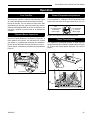
WARNING:
FIRE OR EXPLOSION HAZARD
Failure to follow safety warnings exactly
could result in serious injury, death or
property damage.
•
•
•
Do not store or use gasoline or other
flammable vapors and liquids in the
vicinity of this or any other appliance.
WHAT TO DO IF YOU SMELL GAS
–Do not try to light any appliance.
–Do not touch any electrical switch; do
not use any phone in your building.
–Leave the building immediately.
–Immediately call your gas supplier from
a neighbor's phone. Follow the gas
supplier's instructions.
–If you cannot reach your gas supplier,
call the fire department.
Installation and service must be performed
by a qualified installer, service agency or
the gas supplier.
WARNING: Improper installation, adjustment,
alteration, service or maintenance can cause
injury or property damage. Refer to this manual.
For assistance or additional information consult
a qualified installer, service agency or the
gas supplier.
DANGER
5123
Oxford cover
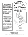
HOT GLASS WILL
CAUSE BURNS.
DO NOT TOUCH GLASS
UNTIL COOLED.
NEVER ALLOW CHILDREN
TO TOUCH GLASS.
A barrier designed to reduce the risk of burns from the hot
viewing glass is provided with this appliance and shall
be installed for the protection of children and
other at risk individuals.
20306543
This appliance is for use only with the type of gas
indicated on the rating plate. This appliance is
not convertible for use with other gases, unless
a certified kit is used.
This appliance may be installed in an aftermarket,*
permanently located, manufactured home (USA
only) or mobile home, where not prohibited by
local codes.
* Aftermarket: Completion of sale, not for purpose of resale, from
the manufacturer.
INSTALLER: Leave this manual with the appliance.
CONSUMER: Retain this manual for future
reference.
20306762 12/14 Rev. 1
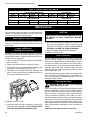
Oxford Direct Vent / Natural Vent Gas Heater
Table of Contents
PLEASE READ THE INSTALLATION & OPERATING INSTRUCTIONS BEFORE USING APPLIANCE.
Thank you and congratulations on your purchase of an Vermont Castings Group stove.
IMPORTANT: Read all instructions and warnings carefully before starting installation. Failure to follow these
instructions may result in a possible fire hazard and will void the warranty.
INSTALLATION & OPERATING INSTRUCTIONS
General Information. . . . . . . . . . . . . . . . . . . . . . . . . . . . . . . . . . 3
Requirements for the Commonwealth of Massachusetts . . . . . 4
Oxford Dimensions . . . . . . . . . . . . . . . . . . . . . . . . . . . . . . . . . . 5
Installation Requirements . . . . . . . . . . . . . . . . . . . . . . . . . . . . . 6
Locating the Stove. . . . . . . . . . . . . . . . . . . . . . . . . . . . . . . . . . . 6
Clearance Requirements. . . . . . . . . . . . . . . . . . . . . . . . . . . . . . 6
Parallel Installation . . . . . . . . . . . . . . . . . . . . . . . . . . . . . . . . . . 7
Corner Installation. . . . . . . . . . . . . . . . . . . . . . . . . . . . . . . . . . . 7
Wall Centerline from Floor. . . . . . . . . . . . . . . . . . . . . . . . . . . . . 7
Wall and Ceiling Clearances. . . . . . . . . . . . . . . . . . . . . . . . . . . 7
Hearth Requirements . . . . . . . . . . . . . . . . . . . . . . . . . . . . . . . . 7
Gas Specifications. . . . . . . . . . . . . . . . . . . . . . . . . . . . . . . . . . . 8
Gas Inlet and Manifold Pressures. . . . . . . . . . . . . . . . . . . . . . . 8
High Elevations. . . . . . . . . . . . . . . . . . . . . . . . . . . . . . . . . . . . . 8
Horizontal Termination - Direct Vent ONLY. . . . . . . . . . . . . . . . 8
Vertical Termination - Direct Vent ONLY. . . . . . . . . . . . . . . . . . 9
Vent Termination Clearances. . . . . . . . . . . . . . . . . . . . . . . . . . . 9
General Venting Information - Termination Location. . . . . . . . 11
Termination Clearances. . . . . . . . . . . . . . . . . . . . . . . . . . . . . . 12
Venting Requirements - Natural Vent ONLY. . . . . . . . . . . . . . 12
Venting Requirements and Options - Direct Vent ONLY. . . . . 13
Install the Optional Fan. . . . . . . . . . . . . . . . . . . . . . . . . . . . . . 14
Venting System Assembly - Direct Vent . . . . . . . . . . . . . . . . . 15
Install Vent Adapter Pipe
(Vermont Castings Group Vent Components) . . . . . . . . . 15
Install Vent Adapter Pipe (Dura-Vent Components) . . . . . . . . 16
Side Wall Termination Assembly. . . . . . . . . . . . . . . . . . . . . . . 16
Vent Termination Below Grade . . . . . . . . . . . . . . . . . . . . . . . . 18
Vertical (Through the Roof) Vent Assembly. . . . . . . . . . . . . . . 18
Venting System Assembly - Natural Vent . . . . . . . . . . . . . . . . 19
Install the Vent Pipe. . . . . . . . . . . . . . . . . . . . . . . . . . . . . . . . . 19
Install the Log Set. . . . . . . . . . . . . . . . . . . . . . . . . . . . . . . . . . 20
Connect Gas Supply Line. . . . . . . . . . . . . . . . . . . . . . . . . . . . 20
Burner Information. . . . . . . . . . . . . . . . . . . . . . . . . . . . . . . . . . 21
Air Shutter Adjustment & Instructions . . . . . . . . . . . . . . . . . . . 21
Complete the Assembly. . . . . . . . . . . . . . . . . . . . . . . . . . . . . . 22
Install ON/OFF Switch. . . . . . . . . . . . . . . . . . . . . . . . . . . . . . . 22
Thermostat Connection (Optional) . . . . . . . . . . . . . . . . . . . . . 23
Install the Front. . . . . . . . . . . . . . . . . . . . . . . . . . . . . . . . . . . . 23
Safety Barrier Installation . . . . . . . . . . . . . . . . . . . . . . . . . . . . 24
MAINTENANCE
Annual System Inspection. . . . . . . . . . . . . . . . . . . . . . . . . . . .
Logset and Burner/Cleaning and Inspection. . . . . . . . . . . . . .
Care of Cast Iron. . . . . . . . . . . . . . . . . . . . . . . . . . . . . . . . . . .
Cleaning the Glass . . . . . . . . . . . . . . . . . . . . . . . . . . . . . . . . .
Glass Replacement. . . . . . . . . . . . . . . . . . . . . . . . . . . . . . . . .
Gasket Replacement. . . . . . . . . . . . . . . . . . . . . . . . . . . . . . . .
Inspect the Vent System Annually. . . . . . . . . . . . . . . . . . . . . .
Check the Gas Flame Regularly. . . . . . . . . . . . . . . . . . . . . . .
Stove Disassembly . . . . . . . . . . . . . . . . . . . . . . . . . . . . . . . . .
Wiring Diagram. . . . . . . . . . . . . . . . . . . . . . . . . . . . . . . . . . . .
30
30
30
30
30
31
31
31
31
32
REPLACEMENT PARTS . . . . . . . . . . . . . . . . . . . . . . . . . . . . 33
OPTIONAL ACCESSORIES . . . . . . . . . . . . . . . . . . . . . . . . . 35
WARRANTY. . . . . . . . . . . . . . . . . . . . . . . . . . . . . . . . . . . . . . 43
EFFICIENCIES. . . . . . . . . . . . . . . . . . . . . . . . . . . . . . . . . . . . 44
OPERATION
Your First Fire . . . . . . . . . . . . . . . . . . . . . . . . . . . . . . . . . . . . . 25
Pilot and Burner Information. . . . . . . . . . . . . . . . . . . . . . . . . . 25
Flame & Temperature Adjustment . . . . . . . . . . . . . . . . . . . . . 25
Flame Characteristics. . . . . . . . . . . . . . . . . . . . . . . . . . . . . . . 25
Lighting and Operating Instructions. . . . . . . . . . . . . . . . . . . . . 26
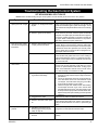
Troubleshooting - SIT NOVA 820 Gas Control System. . . . . . 27
Fuel Conversion Instructions. . . . . . . . . . . . . . . . . . . . . . . . . . 28
Conversion Precautions . . . . . . . . . . . . . . . . . . . . . . . . . . . . . 28
Conversion Procedure. . . . . . . . . . . . . . . . . . . . . . . . . . . . . . . 28
2
20306762
Oxford Direct Vent / Natural Vent Gas Heater
General Information
The Oxford Direct Vent/Natural Vent Room Heater, Model
No. OXDV30NV, is a vented gas appliance listed to the ANSI
standard Z21.88-2009 and CSA-2.33-2009 for Vented Room
Heaters, and CSA 2.17-M91, Gas-Fired Appliances For Use
at High Altitudes.
The installation of the Oxford Direct Vent/Natural Vent Room
Heater must conform with local codes, or in the absence of local codes, with National Fuel Gas Code, ANSI Z223.1/NFPA
54 — latest edition and CSA B-149.1 Installation Code. (EXCEPTION: Do not derate this appliance for altitude. Maintain
the manifold pressure at 3.5” w.c. for Natural Gas and 10.0”
w.c. for LP gas at maximum input.)
This appliance is only for use with the type of gas indicated
on the rating plate. This appliance is not convertible for use
with other gases unless a certified kit is used.
Installation and replacement of gas piping, gas utilization equipment or accessories, and repair and servicing of equipment shall be performed only by a qualified
agency, preferably NFI or WETT (Canada) certified. The
term “qualified agency” means any individual, firm, corporation, or company that either in person or through a
representative is engaged in and is responsible for (a)
installation or replacement of gas piping, or (b), the connection, installation, repair, or servicing of equipment,
who is experienced in such work, familiar with all precautions required, and has complied with all the requirements of the authority having jurisdiction.
The Oxford Direct Vent/Natural Vent Room Heater should
be inspected before use and at least annually by a qualified service agency. It is imperative that control compartments, burners, and circulating air passageways of the
appliance be kept clean.
The Oxford Direct Vent/Natural Vent Room Heater and its
individual shut-off valve must be disconnected from the gas
supply piping during any pressure testing of that system at
test pressures in excess of 1/2 psig (3.5 kPa).
The Oxford Direct Vent/Natural Vent Room Heater must be
isolated from the gas supply piping system by closing its individual manual shutoff valve during any pressure testing of
the gas supply piping system at test pressures equal to or
less than 1/2 psig.
‘Direct Vent’ describes a sealed combustion system in which
incoming outside air for combustion and outgoing exhaust enter and exit through two separate concentric passages within
the same sealed vent system. The system does not use room
air to support combustion. The Direct Vent system permits
the gas appliance to be vented directly to the outside atmosphere through the side of the house or vertically through the
roof. Conventional venting systems (Natural Vent) take air
from the room for combustion and vent the exhaust vertically
through the roof to the atmosphere.
This appliance is approved for bedroom installations in the
U.S. and Canada.
This appliance may be installed in an aftermarket* manufactured (mobile) home, where not prohibited by state or local
codes.
20306762
WARNING: Operation of this heater when not connected
to a properly installed and maintained venting system
can result in carbon monoxide (CO) poisoning and possible death.
The Oxford Direct Vent/Natural Vent Room Heater, when
installed, must be electrically grounded in accordance with
local codes or, in the absence of local codes, with the National Electrical Code ANSI/NFPA 70, (latest edition), or of
the current Canadian Electrical Code C22.1.
Due to high temperatures this appliance should be located out of traffic and away from furniture and draperies.
WARNING: This appliance is hot while in operation.
Keep children, clothing, and furniture away. Contact
may cause burns or ignition of combustible materials.
Children and adults should be alerted to the hazards
of high surface temperatures and should stay away to
avoid burns or clothing ignition. Young children should
be carefully supervised when they are in the same room
as the appliance.
Clothing or other flammable materials should not be
placed on or near the appliance.
Any safety screen, glass or guard removed for servicing an appliance must be replaced prior to operating the
appliance.
The appliance area must be kept clear and free from
combustible materials, gasoline, and other flammable
vapors and liquids.
The flow of combustion and ventilation air must not be
obstructed. The installation must include adequate accessibility and clearance for servicing and proper operation.
WARNING: Do not operate the Room Heater with the
glass panel removed, cracked or broken. Replacement
of the panel should be done by a licensed or qualified
service person.
Do not use this appliance if any part has been under
water. Immediately call a qualified service technician to
inspect the appliance and to replace any part of the control system and any gas control which has been under
water.
Do not burn wood, trash or any other material for which
this appliance was not designed. This appliance is designed to burn either natural gas or propane only.
This gas appliance must not be connected to a chimney
flue serving a separate solid-fuel burning appliance.
CAUTION: Label all wires prior to disconnection when
servicing controls. Wiring errors can cause improper
and dangerous operation.
Verify proper operation after servicing.
Proposition 65 Warning: Fuels used in gas, woodburning or
oil fired appliances, and the products of combustion of such
fuels, contain chemicals known to the State of California to
cause cancer, birth defects and other reproductive harm.
California Health & Safety Code Sec. 25249.6
* Aftermarket: Completion of sale, nor for purpose of resale, from the
manufacturer.
3
Oxford Direct Vent / Natural Vent Gas Heater
Requirements for the Commonwealth of Massachusetts
All gas fitting and installation of this heater shall only be
done by a licensed gas fitter or licensed plumber.
For all side wall horizontally vented gas fueled equipment
installed in every dwelling, building or structure used in whole
or in part for residential purposes, including those owned
or operated by the Commonwealth and where the side wall
exhaust vent termination is less than seven (7) feet above
finished grade in the area of the venting, including but not
limited to decks and porches, the following requirements
shall be satisfied:
Installation of Carbon Monoxide Detectors
At the time of installation of the side wall horizontal vented
gas fueled equipment, the installing plumber or gas fitter
shall observe that a hard wired carbon monoxide detector
with an alarm is installed on each additional level of the
dwelling, building or structure served by the side wall
horizontal vented gas fueled equipment. It shall be the
responsibility of the property owner to secure the services
of qualified licensed professionals for the installation of
hard wired carbon monoxide detectors.
In the event that the side wall horizontally vented gas fueled
equipment is installed in a crawl space or an attic, the hard
wired carbon monoxide detector with alarm and battery
back-up may be installed on the next adjacent floor level.
In the event that the requirements of this subdivision can not
be met at the time of completion of installation, the owner
shall have a period of thirty (30) days to comply with the
above requirements; provided, however, that during said
thirty (30) day period, a battery operated carbon monoxide
detector with an alarm shall be installed.
Approved Carbon Monoxide Detectors
Each carbon monoxide detector as required in accordance
with the above provisions shall comply with NFPA 720 and
ANSI/UL 2034 listed and IAS certified.
Signage
A metal or plastic identification plate shall be permanently
mounted to the exterior of the building at a minimum height
of eight (8) feet above grade directly in line with the exhaust
vent terminal for the horizontally vented gas fueled heating
appliance or equipment. The sign shall read, in print size no
less than one-half (1/2) inch in size, “GAS VENT DIRECTLY
BELOW, KEEP CLEAR OF ALL OBSTRUCTIONS”.
Inspection
Exemptions
The following equipment is exempt from 248 CMR
5.08(2)(a)1 through 4:
• The equipment listed in Chapter 10 entitled “Equipment
•
Not Required To Be Vented” in the most current edition
of NFPA 54 as adopted by the Board; and
Product Approved side wall horizontally vented gas fueled
equipment installed in a room or structure separate from
the dwelling, building or structure used in whole or in
part for residential purposes.
MANUFACTURER REQUIREMENTS
Gas Equipment Venting System Provided
When the manufacturer of Product Approved side wall
horizontally vented gas equipment provides a venting
system design or venting system components with the
equipment, the instructions provided by the manufacturer
for installation of the equipment and the venting system
shall include:
• Detailed instructions for the installation of the venting
•
system design or the venting system components;
and
A complete parts list for the venting system design or
venting system.
Gas Equipment Venting System NOT Provided
When the manufacturer of a Product Approved side wall
horizontally vented gas fueled equipment does not provide
the parts for venting the flue gases, but identifies “special
venting systems”, the following requirements shall be
satisfied by the manufacturer:
• The referenced “special venting system” instructions shall
•
be included with the appliance or equipment installation
instructions; and
The “special venting systems” shall be Product
Approved by the Board, and the instructions for that
system shall include a parts list and detailed installation
instructions.
A copy of all installation instructions for all Product Approved
side wall horizontally vented gas fueled equipment, all
venting instructions, all parts lists for venting instructions,
and/or all venting design instructions shall remain with
the appliance or equipment at the completion of the
installation.
The state or local gas inspector of the side wall horizontally
vented gas fueled equipment shall not approve the
installation unless, upon inspection, the inspector observes
carbon monoxide detectors and signage installed in
accordance with the provisions of 248 CMR 5.08(2)(a)1
through 4.
4
20306762
Oxford Direct Vent / Natural Vent Gas Heater
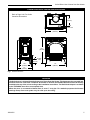
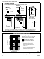
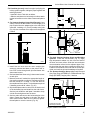
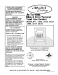
Oxford Direct Vent / Natural Vent Dimensions
Refer to Page 6 for Flue Collar
Centerline Dimensions
6³⁄₄" (172mm) C L Valve Inlet 24¹⁄₂" (622mm) 28³⁄₈" (721mm) C Valve 4³⁄₈" L Inlet (111mm) 12¹⁄₂" (318mm) 23" (584mm) 17" (419mm) Fig. 1 Oxford dimensions.
5123 Oxford dims
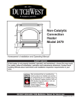
Attention
The Oxford stove is shipped from the factory as a Direct Vent Gas Heater. This heater may be converted into
a Natural Vent unit in the field. If a Natural Vent heater is desired, the FSDHAG Draft Hood must be directly
installed to the top of the unit according to the installation instructions. The Draft Hood Adapter is available
in the 7FSDHASK stove kit or as a separate item.
When the stove is converted to Natural Vent, it uses 4” vent pipe. For aesthetic purposes the Vermont
Castings Group direct vent system may be used up to the ceiling.
20306762
5
Oxford Direct Vent / Natural Vent Gas Heater
Installation Requirements
The installation must conform with local codes or, in the
absence of local codes, with the National Fuel Gas Code,
ANSI Z223.1/NFPA 54 - latest edition. (EXCEPTION: Do
not derate this appliance for altitude. Maintain the manifold pressure at 3.5” w.c. for Natural Gas, and 10” w.c. for
Propane).
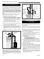
Direct Vent System Only
A
In Canada, installation must be in accordance with the current CSA B-149.1 Installation Codes and/or local codes.
C
The installation should be done by a qualified service
person who is familiar with the building codes and
installation techniques appropriate for your area to
accomplish a safe and effective installation.
Your dealer or your local gas supplier will be able to
refer a qualified service person.
WARNING: Due to high temperatures, the
HEATER should be located out of traffic and
away from furniture and draperies.
The surface of the Heater Is hot when it is in use.
Young children should be watched carefully when
they are in the same room when the Heater is in use,
and they should be taught to avoid the hot surface.
Keep any objects that can burn well away from the
Heater, and observe the recommended clearances
that follow.
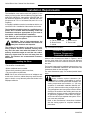
Locating the Stove
In choosing a location for the stove, consider:
• The location of outside walls;
• Where additional heat is needed:
• Where family members gather most often;
• The vent system requirements.
NOTE: We do not recommend the use of wallpaper next
to this stove. Over time, radiant heat may cause the wallpaper to shrink, or may adversely affect the binders in the
wallpaper adhesive.
6
D
B
E
A. Flat on corner wall
B. Room Divider
ST207b
C. Island
D. Cross Corner
E. Flat on wall
Dutchwest
ST207b
Stove locations
Fig. 2 Possible stove locations.
5/15/03 djt
Clearance Requirements:
Minimum Clearances to
Combustible Materials
Measure side clearances as shown in Figures 5 and 6
from the outer edge of the cast iron stove top. Measure
rear clearances from the outermost surface of the steel
rear skirt.
The heater is approved for installation into an alcove constructed of combustible materials to the dimensions and
clearances shown on the next page.
The same clearances apply in a standard parallel installation.
WARNING:
Always maintain required clearances (air
spaces) to nearby combustibles to prevent
fire hazard. Do not fill air spaces with insulation. All
venting components must maintain a 1” (25 mm)
clearance to combustible materials. Maintain a 6”
(150 mm) clearance when using a single wall pipe.
• The gas appliance and vent system must be vented
directly to the outside of the building and never be
attached to a chimney serving a separate solid fuel
or gas-burning appliance. Each direct vent appliance must use its own separate vent system. Common vents are prohibited.
• Refer to the manufacturer’s instructions included
with the venting system for complete installation
procedures.
20306762
Oxford Direct Vent / Natural Vent Gas Heater
Parallel Installation:
Minimum Clearance and Flue Centerline,
Direct Vent and Natural Vent
Wall Centerline from Floor
C
L
C
A
D
A
C
L
B
Stove Clearances
Pipe Centerlines
A: 4" (102 mm)
B: 4" (102 mm)
C: 151⁄2" (395 mm)
D:
9" (229 mm)
ST128b
ST1121
A
Effective Minimum
Wall Thimble
571⁄2" (1461 mm) (Vermont Castings Group
Pipe)
ST1121
Centerline
531⁄2" (1359 mm) (Simpson DuraVent Pipe)
ST128c
Fig. 3 Parallel installation,
minimum back and side clearances
Stardance
and flue centerlines.
flue centerline
Corner
Installation:
9/28/00
djt
Minimum Clearance and Flue Centerline
Direct Vent and Natural Vent
wall thimble
Fig. 5 Minimum wall thimble centerline.
Wall and Ceiling Clearances
D
B
B
A
C
B
A
A: Rear Wall
4" (102 mm)
B: Min. Clearance
451⁄2" (1156 mm)*
ST1122
1
C: Min. Alcove Height Min.
73clearance
⁄2" (1867 mm)*
D: Max. Alcove Depth
48" (1220 mm)
Sidewall Clearance
4" (102 mm)
A
Stove Clearance
Pipe Centerline
A: 4" (102 mm)
B: 141⁄2" (370 mm)
ST129c
Fig. 4 Corner installation, minimum corner clearances and flue
ST129c
centerline.
Dutchwest
corner specs
5/15/03 djt
20306762
* needed for installing DuraVent Minimum Vent Kit #2792 or Vermont CastST1122
ings Group Minimum Vent Kit #7TFSDVSK.
Fig. 6 Dimensions and clearances to ceiling or alcove.
Hearth Requirements
The heater must be installed on rigid flooring. When the
heater is installed directly on any combustible surface
other than wood flooring, a metal or wood panel extending the full width and depth of the unit must be used as the
hearth. There are no other hearth requirements.
7
Oxford Direct Vent / Natural Vent Gas Heater
Horizontal Termination Direct Vent ONLY
Gas Specifications
Model Fuel Gas Control
2465 Nat
Millivolt
2466 Prop
Millivolt
Max. Min.
Input Input
BTU/h BTU/h
28,000 20,000
28,000 19,000
Weight: Fully assembled; 202 lbs.
Gas Inlet and Manifold Pressures
Inlet Minimum
Inlet Maximum
Manifold Pressure
Natural
5.5” w.c.
14.0” w.c.
3.5” w.c.
LP (Propane)
11.0” w.c.
14.0” w.c.
10.0” w.c.
The vent must rise vertically a minimum of 24” (610 mm)
off the top of the unit, before the first elbow. The horizontal
run may extend up to 20’ (6 m) and include a vertical rise
of up to 40’ (12 m). (Fig. 7) Horizontal termination must
also meet the criteria shown in Figures 9 through 11.
• Approved vent systems must terminate above and including the heavy line in Figure 7.
• Two 45° elbows may be substituted for each single 90°
elbow.
• With a rise between 2’ - 5’, one 90° or two 45° elbows
may be used.
Oxford Direct Vent/Natural Vent
Certified to:
ANSI Z21.88 / CSA 2.33 Latest Edition
Vented Gas Fireplace Heaters
WARNING: Improper installation, adjustment, alteration, service or maintenance can cause injury or
property damage. Refer to this manual for correct
installation and operational procedures. For assistance or additional information consult a qualified
installer, service agency, or the gas supplier.
38
37
36
35
Vertical Run (in feet)
High Elevations
Input ratings are shown in BTU per hour and are
certified without deration for elevations up to 4,500
feet (1,370 m) above sea level.
For elevations above 4,500 feet (1,370 m) in USA,
installations must be in accordance with the current ANSI Z223.1/NFPA 54 and/or local codes having jurisdiction.
In Canada, please consult provincial and/or local
authorities having jurisdiction for installations at
elevations above 4,500 feet (1,370 m).
39
(Measured from the appliance flue collar to the top of the vent pipe.)
The installation of your stove must conform with
local codes, or in the absence of local codes, with
the National Fuel Gas Code ANSI Z223.1/NFPA 54 latest edition, or CSA B149.1 Installation code. (EXCEPTION: Do not derate this appliance for altitude
up to 4,500 feet (1,370 m). Maintain the manifold
pressure at 3.5” w.c. for Natural Gas and 10.0” w.c.
for LP Gas.
40
34
33
32
31
30
29
May use up to three
90° Elbows
28
27
26
ST134a
FDV28
Horizontal
vent run
12/3/99 djt
areas modified
1/11/00 djt
25
24
23
22
21
20
19
18
16
15
14
13
12
11
10
9
8
7
6
5
One 90°
Elbow
4
3
Unacceptable Venting
Configuration
2
1
0
1 2
3
4
5
6
7
8
9
10 11 12 13 14 15 16 17 18 19 20
Horizontal Run (in feet)
ST134a
Fig. 7 Horizontal vent termination window.
8
20306762
Oxford Direct Vent / Natural Vent Gas Heater
Vertical Termination - Direct Vent ONLY
Vent Termination Clearances
A vertical vent system must terminate no less than 8'
(2.44 m) and no more than 40' (12 m) above the appliance flue collar. A 21⁄4" restrictor plate (supplied) must be
used where specified in all vertically terminated vent systems. (Fig. 8) NOTE: The restrictor plate supplied with
the vertical termination should be discarded. Install
restrictor plate supplied with stove directly at stove
outlet. A vertically terminated vent system must also conform to the following criteria:
When planning the installation, consider the location of
the vent terminal and clearances. Some of the most common clearances to keep in mind are shown in Figure 10.
• No more than three 90° elbows may be used.
• Two 45° elbows may be substituted for one 90° elbow.
No more than six elbows may be used.
• Vent must rise a minimum of 2 feet before offset is
used.
• Termination height must conform to roof clearance as
specified in Figure 9.
40
39
All Vertical Terminations in this area
Require use of the
21⁄4" Restrictor Plate*
38
37
36
Vertical Run (in feet)
(Measure from the appliance flue collar to the top of the vent pipe.)
35
34
33
32
31
30
29
28
27
26
25
24
23
Vertical terminations
must be within this area
21
20
19
18
16
e
14
12
11
10
or
ict
13
No
tr
es
at
Pl
Unacceptable Venting
Configuration
R
The vent should be placed so that people cannot be
burned by accidentally touching the vent surfaces when
the stove is operating.
The vent termination should be located where it cannot be
damaged by such things as automobile doors, lawn mowers or snowblowers and it should be located away from
areas where it could become blocked by snow, etc.
Some considerations are:
• Obstructions or impediments to venting.
• Nearby combustible materials that could come into
contact with combustion exhaust gases.
• Other nearby openings {within 12” (305 mm)} through
which exhaust gas could reenter the building.
• All vegetation within 3’ (76 mm) that may interfere with
the draft.
Other factors that influence where the installation will be
sited include the location of outside walls, where additional heat may be desired in the home, where the family
members gather most regularly, and perhaps most importantly, the distance limitations of the venting system.
ST132a
FDV28
Vertical
vent run
12/3/99 djt
area
modified
1/11/00 djt
22
15
Important: All vent clearances must be maintained.
Check your vent termination clearances against Figures 9 through 11.
9
8
7
6
5
4
3
2
IMPORTANT
Direct Vent Only
• The horizontal termination must not be recessed
into the exterior wall or siding.
• Horizontal vent runs must be level toward the vent
termination.
• Clearances around the vent termination must be
maintained.
• For installations using Simpson DuraVent pipe, parallel installations with minimum wall clearance have
restricted access for connecting the Horizontal Vent
Cap straps to the vent pipe. See the maker’s instructions for recommended installation procedures.
1
0
1
2
3
4
5
6
7
8 9
10 11 12 13 14 15 16 17 18 19 20
Horizontal Run (in feet)
ST132a
Fig. 8 Vertical vent termination window.
*The Restrictor Plate is used on Direct Vent Installations
Only
20306762
9
Oxford Direct Vent / Natural Vent Gas Heater
Venting Termination Clearances
Your stove is approved to be vented either through the
side wall, or vertical through the roof.
• This unit does not require any opening for inspection of vent pipe.
• Only Vermont Castings Group and Duravent venting components specifically approved and labelled
for this stove may be used.
• Minimum clearances between vent pipes and combustible materials is one (1”) inch (25 mm), except
where stated otherwise.
• Venting terminals shall not be recessed into a wall or
siding.
• Horizontal venting must be installed on a level plane
without an inclining or declining slope.
10
There must not be any obstruction such as bushes, garden sheds, fences, decks or utility buildings within 24”
from the front of the termination hood.
Do not locate termination hood where excessive snow or
ice build up may occur. Be sure to check vent termination area after snow falls, and clear to prevent accidental
blockage of venting system. When using snow blowers,
make sure snow is not directed towards vent termination
area.
Location of Vent Termination
It is imperative the vent termination be located observing
the minimum clearances as shown on this page.
20306762
Oxford Direct Vent / Natural Vent Gas Heater
General Venting Information - Termination Location
INSIDE
CORNER DETAIL
G
V
H
A
N
N
D
L
V
E
C
B
V
F
B
Fixed
Closed
Ope
Operable
rable
V
B
CFM145a
V VENT TERMINATION
B
V
B
V
V
Fixed
Closed
B
J
X
X AIR SUPPLY INLET
M
I
A
V
K
X
AREA WHERE TERMINAL IS NOT PERMITTED
Canadian Installations1
US Installations2
A = Clearance above grade, veranda, porch, 12” (30cm)
12” (30cm)
CFM145a
DV Termin Location
deck, or balcony
Rev. 12/05/01
B = Clearance to window or door that may be 5/01/01
6” (15cm)
for appliances 6” (15cm) for appliances
sta
opened
< 10,000Btuh (3kW), 12” (30cm) < 10,000 Btuh (3kW), 9”
for appliances > 10,000 Btuh (3kW) and
(23cm) for appliances > 10,000
< 100,000 Btuh (30kW), 36” (91cm)
Btuh (3kW) and < 50,000 Btuh
for appliances > 100,000 Btuh (30kW)
(15kW), 12” (30cm) for appliances > 50,000 Btuh (15kW)
C = Clearance to permanently closed window
12” (305mm) recommended to
12” (305mm) recommended to
prevent window condensation
prevent window condensation
D = Vertical clearance to ventilated soffit located
above the terminal within a horizontal 18” (458mm)
18” (458mm)
distance of 2 feet (610mm) from the center
line of the terminal
E = Clearance to unventilated soffit
12” (305mm)
12” (305mm)
F = Clearance to outside corner see next page
see next page
G =Clearance to inside corner (see next page) see next page
see next page
H = Clearance to each inside of center line
3’ (91cm) within a height of 15’ (5m)
3’ (91cm) within a height of 15’
extended above meter/regulator assembly
above the meter/regulator assembly
(5m) above the meter/regulator assy
I = Clearance to service regulator vent outlet
3’ (91cm)
3’ (91cm)
J = Clearance to nonmechanical air supply inlet 6” (15cm) for appliances < 10,000
6” (15cm) for appliances
to building or the combustion air inlet to any Btuh (3kW), 12” (30cm) for
< 10,000 Btuh (3kW), 9”
other appliances
appliances > 10,000 Btuh (3kW) and (23cm) for appliances > 10,000
< 100,000 Btuh (30kW), 36” (91cm)
Btuh (3kW) and < 50,000 Btuh
for appliances > 100,000 Btuh (30kW)
(15kW), 12” (30cm) for appliances > 50,000 Btuh (15kW)
K = Clearance to a mechanical air supply inlet
6’ (1.83m)
3’ (91cm) above if within 10’
(3m) horizontally
L = Clearance above paved sidewalk or paved 7’ (2.13m)†
7’ (2.13m)†
driveway located on public property
M =Clearance under veranda, porch, deck or
12” (30cm)*
12” (30cm)*
balcony
N = Clearance above a roof shall extend a minimum of 24” (610mm) above the highest point when it passes through the roof surface, and any other obstruction within a horizontal distance of 18” (450mm).
1 In accordance with the current CSA-B149 Installation Codes
2 In accordance with the current ANSI Z223.1/NFPA 54 National Fuel Gas Codes
† A vent shall not terminate directly above a sidewalk or paved driveway which is located between two single family dwellings and serves both dwellings
* only permitted if veranda, porch, deck or balcony is fully open on a minimum 2 sides beneath the floor:
NOTE: 1. Local codes or regulations may require different clearances.
2. The special venting system used on Direct Vent appliances are certified as part of the appliance, with clearances tested and approved by the listing agency.
3.Vermont Castings Group assumes no responsibility for the improper performance of the appliance when the venting system does not meet these requirements.
Fig. 9 Vent termination clearances.
20306762
11
Oxford Direct Vent / Natural Vent Gas Heater
Termination Clearances
Termination clearances for buildings with combustible and noncombustible exteriors.
Alcove Applications*
Inside Corner
Outside Corner
G=
Combustible
6" (152 mm)
G
F=
Combustible
6" (152 mm)
Noncombustible
2" (51 mm)
V
Noncombustible
2" (51 mm)
V
C
V
E
O
F
Balcony with perpendicular side wall
Balcony with no side wall
D
C
E = Min. 6” (152 mm) for
non-vinyl sidewalls
Min. 12” (305 mm) for
vinyl sidewalls
O = 8’ (2.4 m) Min.
M
M
V
V
P
Combustible &
Noncombustible
M=
Combustible &
Noncombustible
12" (305 mm)
No.
of Caps
DMin.CMax.
1
3’ (914 mm) 2 x DActual
2
6’ (1.8 m)
1 x DActual
3
9’ (2.7 m)
2/3 x DActual
4
12’ (3.7 m) 1/2 x DActual
M = 24" (610 mm)
P = 20” (508 mm)
DMin. = # of Termination caps x 3
CMax. = (2 / # termination caps) x DActual
584-15
*NOTE: Termination in an alcove space (spaces open only on one side and with an overhang) is permitted with the dimensions
specified for vinyl or non-vinyl siding and soffits. 1. There must be a 3’ (914 mm) minimum between termination caps. 2. All
mechanical air intakes within 10’ (1 m) of a termination cap must be a minimum of 3’ (914 mm) below the termination cap. 3. All
gravity air intakes within 3’ (914 mm) of a termination cap must be a minimum of 1’ (305 mm) below the termination cap.
Fig. 10 Termination clearances.
Venting Requirements - Natural Vent Only
36
Vertical Run (in feet)
(Measured from top of the unit before any elbow)
34
Venting Runs
A
32
B
30
28
26
NOTE: When venting staight vertical, without any
elbow, a minimum of 8 ft. vertical is required
off the top of the stove.
= Acceptable venting configuration
24
= Unacceptable venting configuration
22
20
A: Vertical installations up to 36 feet (12m) in
height. Up to an 18 ft. horizontal vent run can be
installed within the vent system using a
maximum of two 90-degree elbows or four
45-degree elbows.
18
16
14
12
10
B: Vertical installations up to 36 feet (12m) in
height. Up to a 24 ft. horizontal vent run can be
installed within the vent system using a
maximum of two 45-degree elbows.
(Ratio = 2/3, Hor./Vert.)
8
6
4
2
1 2 4
6 8 10 12 14 16 18 20 22 24
FP567b
Horizontal Run (in feet)
Fig. 11 Vent termination window - Natural Vent ONLY.
12
NOTE: When using the FSDHAG, the restrictor
plate supplied with the stove is not used.
FP567
NVBR/NVBC VENTING RUNS
11/12/97
20306762
Oxford Direct Vent / Natural Vent Gas Heater
Venting Requirements and Options Direct Vent ONLY
Approved Vent System Components
The heater must be vented to the outdoors through an adjacent
exterior wall or through the roof. The venting system must be
comprised of the appropriate listed venting components specified on this page. These parts are available from DuraVent Corporation or your Vermont Castings Group Dealer.
Refer to Figure 4 for dimensions relevant to the standard minimum-vent kits.
Simpson DuraVent Components
www.duravent.com
Phone: 1-800-835-4429, Fax: 1-707-446-4740
Minimum Horizontal Vent Kit
2792
Starter Pipe Assembly (incl. inner & outer sections)
2768*
90° Elbow, Blk.
46DVA-E90B*
45° Elbow, Gal.
46DVA-E45
6" Straight, Blk.
46DVA-D6B*
9" Straight, Blk.
46DVA-09B
46DVA-08AB
11" - 145⁄8" Adjustable Straight Section 12" Straight
46DVA-12
24" Straight
46DVA-24B*
36" Straight
46DVA-36B
48" Straight
46DVA-48
Horizontal Vent Cap
46DVA-HC*
Wall Plate
46DVA-DC
Vinyl Siding Shield
46DVA-VSS
Snorkel Termination - 14"
46DVA-SNK-14
Snorkel Termination - 36"
46DVA-SNK30
Wall Strap
46DVA-WS
Cathedral Ceiling Support Box
46DVA-CS
Storm Collar
46DVA-SC
Wall Thimble
46DVA-WT
Firestop Spacer
46DVA-FS
Flashing 0/12 - 6/12
46DVA-F6
Flashing 6/12 - 12/12
46DVA-F12
Steel Chimney Conversion Kit
Kit A (65⁄8" - 85⁄8")46DVA-KCA
Kit B (65⁄8" - 101⁄2")46DVA-KCB
Kit C (65⁄8" - 13")
46DVA-KCC
Masonry Chimney Kit
46DVA-KMC
Vertical Termination Cap (High Wind)
46DVA-VCH
Vertical Termination Cap (Low Profile)
46DVA-VC
*Included in Minimum Horizontal Vent Kit #2792
All DuraVent Straight vent pipe sections have a net length 11⁄2" (37mm)
less than the nominal dimension; i.e., a 6" (152mm) Straight pipe section has an effective length of 41⁄2" (115mm).
Vermont Castings Group Vent Components
The following kits are available to meet the needs of most installations. All pipe has a 7" outer diameter and includes a 4"
diameter inner section. A (CG) designation indicates the part is
finished in Charcoal Gray paint. Consult your dealer about other
vent parts that may be appropriate to complete the installation.
Through the Wall Vent Kit
(1) 90-Degree Elbow (CG)
(1) 24" termination pipe (CG)
(1) 24-44" Adjustable Section
(1) Side Wall Termination, cool touch with siding shield
(1) Firestop
(1) Zero-clearance sleeve
(1) Hardware package
(1) Finishing plate (CG)
(1) Finishing collar (CG)
(4) Charcoal Gray flue pipe rings
20306762
7TFSSK
Vertical Termination Kit, 1/12-6/12 Pitch (1) Combination Horizontal Offset / Roof Support
(1) Vertical Termination
(1) Storm Collar
(1) 1/12-6/12 Flashing
(1) Finishing Plate (CG)
(1) Finishing Collar (CG)
(1) Polished Brass Flue Pipe Ring
(1) Hardware Package
Vertical Termination Kit, 7/12-12/12 Pitch (1) 7/12 - 12/12 Flashing
and all of the other Vertical Termination parts.
Vertical Termination, Flat Roof
(1) Flat Flashing
and all of the other Vertical Termination parts.
Twist Lock 24” Straight Pipe (CG)
(1) 24” Non-adjustable Pipe
(1) Polished Brass Flue Pipe Ring
Twist Lock 48” Straight Pipe (CG)
(1) 48” Nonadjustable Pipe
(1) Polished Brass Flue Pipe Ring
Twist Lock 45-Degree Elbow (CG)
for vertical offsets
(1) 45-degree Elbow
(1) Polished Brass Flue Pipe Ring
Draft Hood Adapter
Combination Offset/Roof Support
Attic Insulation Shield
7” Charcoal Gray Pipe Rings, (4)
7” Polished Brass Pipe Rings (4)
7TDVSKVA
7TDVSKVB
7DVSKVF
7TFSDVP24
7TFSDVP48
7TFSDVT45
Selkirk Corporation Vent Components
www.selkirkcorp.com
1301 W. President George Bush Highway Ste. 330
Richardson, TX 75080
Phone: 1-800-992-8368, Fax: 1-877-393-4145
Appliance Adapter
90° Elbow, Blk.
45° Elbow, Blk.
6” Straight, Blk.
9” Straight, Blk.
4” - 10” Adjustable Straight Section, Blk.
12” Straight, Blk.
18” Straight, Blk.
24” Straight, Blk.
36” Straight, Blk.
48” Straight, Blk.
Horizontal Vent Cap
Wall Plate
Vinyl Siding Shield
Snorkel Termination - 14”
Snorkel Termination - 36”
Wall Strap
Cathedral Ceiling Support Box
Storm Collar
Firestop Spacer
Flashing 0/12 - 6/12
Flashing 6/12 - 12/12
Steel Chimney
Horizontal Kit A
Horizontal Kit B
Vertical Kit
Masonry Chimney Kit
Vertical Termination Cap
FSDHAG
7DVCS
7DVAIS
7FSDRG
7FSDRP
4DT-AAV
4DT-EL90B
4DT-EL45B
4DT-06B
4DT-09B
4DT-AJ12
4DT-12B
4DT-18B
4DT-24B
4DT-36B
4DT-48B
4DT-HC
4DT-WT
4DT-VS
4DT-ST14
4DT-ST36
4DT-WS/B
4DT-CCS
4DT-SC
4DT-FS
4DT-AF6
4DT-AF12
4DT-HKA
4DT-HKB
4DT-VKC
4DT-MCK
4DT-VC
NOTE: Direct vent pipe may be used on the Natural Vent system
from the top of the draft hood adapter to the ceiling.
13
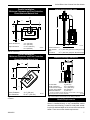
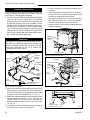
Oxford Direct Vent / Natural Vent Gas Heater
• Remove retaining nut from shaft of rheostat. (if pre-
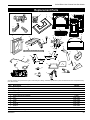
Install the Optional Fan
If you are installing the optional convection Fan Kit #2767
(FK26), continue here. If you are not installing a Fan Kit,
go to Page 15, Venting System Assembly.
1. The fan kit includes a Blower Assembly and a Rheostat
Assembly, connected by a cable. (Fig. 12) The Blower
Assembly mounts to the bottom rear of the stove, and
the Rheostat mounts to the valve coverplate. The assembly includes a ‘snapstat’ which automatically turns
the fan On (or Off) above (or below) approximately
109°. The Rheostat also provides a range of fan speed
settings from Off (which overrides the snapstat function) to High. Unpack and inspect the Blower assembly. Confirm that the fan spins freely.
•
•
•
•
installed)
Insert the rheostat through the hole in the back of
the left side of the valve bracket, aligning the locator
pin with the smaller hole in that bracket.
Thread the retaining nut onto the shaft of the rheostat, tightening with a wrench. Do not overtighten.
Attach the control knob to the rheostat shaft.
Use the wire tie to secure the fan and rheostat wire
harnesses together.
Made
in USA
Rear Skirt
WARNING
Sheet Metal
Screws
This appliance is equipped with a three-prong (grounded) plug for your protection against shock hazard and
should be plugged directly into a properly grounded
three-prong receptacle. Do not cut or remove the
grounding prong from this plug.
Not Used on RF
Models
Not Used
on
Oxford
Snapstat
Bracket
Snapstat/
Extension
Assembly
Rheostat
Assembly
Not Used
on RF
Models
ST757
Rear Skirt Insert
Fig. 13 Remove rear skirt insert.
ST1123
rear skirt insert
Star Washer
Sheet Metal Screws
Phillips 1
Pan Head
Bolts
2
Snapstat
1/4” - 20
Hex Bolt
Star
Washer
3
Snapstat
Bracket
Blower
Assembly
ST473
Connect to PC Board on
RF Models Only
Fig. 12 Fan kit components.
2. Remove the rear skirt insert panel at the bottom of the
ST473
Rear Skirt (Fig. 13)
and fasten the blower assembly to
Fan parts
the firebox back #2767
with FK26
the two Phillips pan-head bolts
originally installed
in the firebox back. (‘1’, Fig. 14)
9/29/00
3. Attach the snapstat assembly to the snapstat bracket
with two sheet-metal screws. (‘2’, Fig. 14) Attach the
snapstat bracket to the stove with a hex-head bolt
passing through the bracket and into the stove base.
(‘3’, Fig. 14)
4. The rheostat control switch attaches to the left side of
the valve bracket at the front of the stove.
14
ST314
Fig. 14 Attach the fan assembly and the snapstat.
ST314
Fk26ce
attach fan
1/24/00
Rheostat
Retaining Collar
Rheostat Knob
Fig. 15 Attach the fan rheostat.
ST758
Dutchwest
attach rheostat
5/15/03 djt
ST758
20306762
Oxford Direct Vent / Natural Vent Gas Heater
Venting System Assembly - Direct Vent
General Information
The Oxford is approved for installation only with the vent
components listed on Page 13. Follow the vent component instructions exactly.
For U.S. installations: The venting system must conform
with local codes and/or the current National Fuel Gas
Code, ANSI Z223.1/NFPA 54.
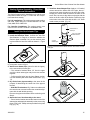
5. Install the Outer Adapter Pipe. Apply a 1/4” bead of
cement around the inside wall of the pipe, about 1”
from the end. Insert the pipe over the stove flue collar,
keeping the vertical seam oriented to the back of the
stove. Also, be sure to align holes on the pipe with the
holes on the flue collar of the firebox. Fasten the pipe
to the holes in the flue collar with the #12 x 1/2” sheet
metal screws provided. (Fig. 19)
For Canadian installations: The venting system must
conform to the current CSA B149.1 installation code.
First Section of
Vent Pipe
Install the Vent Adapter Pipe
(Vermont Castings Group Vent Components)
1. Install the Restrictor Plate. Consult the ‘Vent Run
Specifications’ on Page 8 to determine whether the
restrictor plate is needed. If so, put the restrictor plate
in place within the inner flue collar as shown in Figure
16.
#8 x 1/2” Sheet
Metal Screws
ENT
CEM
4” Inner
Starter Pipe
ST211
Fig. 17 Connect the inner starter with the next section of inner
vent pipe.
ST759
Fig. 16 Install the restrictor plate only if required for the venting configuration. Refer to Page 9.
2. Attach Inner Starter Pipe, (found in with the logset),
to the next section of inner pipe.
• Run a bead of sealant about 1/2” from the upper
end of the Inner starter pipe and join the two sections
together.
• Drill three pilot holes
into the Inner Starter and seST759
cure the assembly with
three
sheet metal screws. (Fig.
Dutchwest
17)
restictor plate
3. Dry fit the Outer pipe assembly to the stove for the
5/15/03
purpose of determining
the center line of the pipe on
the wall.
• Side Wall Terminations: Dry fit the outer elbow with
the vertical outer vent and confirm the centerline alignment with the wall thimble opening.
Remove the pipes and elbows before continuing with
Step 4.
4. Attach the Inner Vent Assembly to the stove.
• Run a bead of sealant around the bottom end of the
starter pipe and attach the assembly to the stove using
three 1/4-20 x 3/8” Phillips screws provided in the parts
bag. (Fig. 18)
20306762
ST211
attach inner
pipe
ENT
CEM
to next section
12/4/99 djt
ST760
Fig. 18 Attach inner assembly to flue collar.
ST760
attach inner assy
5/15/0 3 djt
ST761
Fig. 19 Fasten outer pipe with #12 x 1/2” sheet metal screw.
ST761
attach inner assy
5/15/03 djt
15
Oxford Direct Vent / Natural Vent Gas Heater
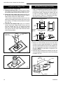
Install the Vent Adapter Pipe
Side Wall Termination Assembly
(Simpson Dura-Vent Components)
1. Install the Restrictor Plate. Consult Page 9 to determine whether the restrictor plate is needed. If so, place
the restrictor plate into the inner flue collar. (Fig. 16)
2. Discard the inner starter pipe shipped with the logset. Using the starter pipe assembly listed on Page 7,
slide the inner section out to allow access.
• Run a bead of sealant around the bottom end of the
starter pipe and attach the assembly to the stove using
three 1/4-20 x 3/8” Phillips screws provided in the parts
bag. (Fig. 20)
3. Install the Outer Adapter Pipe. Apply a 1/4” bead of
cement around the outside surface, about one inch
from the crimped end. (Fig. 21) Orient the vertical
seam to the rear, and insert the crimped end of the
outer pipe into the flue collar. Fasten with three sheet
metal screws provided.
1. Locate the vent opening on the wall. Refer to Figure 5,
Page 7, to determine the opening centerline. It may be
necessary to first position the stove and measure to
find the hole location. Depending on whether the wall
is made of combustible materials, cut the opening to
the size shown in Figure 22. Combustible wall openings must be framed as shown in Figure 22.
Inner Adapter
Pipe
1/4-20 x 3/8
Phillips Screws
Vermont Castings Group System
93⁄8"
(240 mm
93⁄8"
(240 mm
DuraVent
System
Combustible Wall
10"
(250 mm)
Framing Detail
71⁄2"
(191 mm)
10"
(250 mm)
VO584-100
Fig. 22 Locate vent opening.
ENT
CEM
ST762
Fig. 20 Simpson DuraVent - install inner adapter pipe.
2.Measure the wall thickness and cut the wall sleeve
sections to proper length (MAXIMUM 12"). Assemble
the sleeve with the #8 sheet metal screws supplied. Attach the firestop plate to the sleeve end with the holes.
VO584-100
(Fig. 23) NOTE: The
wall sleeve is required in combustible walls only. Vent Opening
2/99 djt assembly into the wall
3. Install the Wall Firestop/Sleeve
cutout and fasten the firestop to the wall cutout framing
members. (Fig. 23)
12"
(305 mm)
Max. Length
Fig. 21
ST762
dura vent
attach inner assy
Simpson DuraVent - install outer adapter pipe.
5/15/03 djt
Sleeve
ST763
Firestop
ZCS103
Fig. 23 Assemble the wall sleeve and firestop.
16
ST763
DW dura vent
attach outer assy
ZCS103
Zero Clearance Sleeve
& Firestop
12/6/99 djt
20306762
Oxford Direct Vent / Natural Vent Gas Heater
For DuraVent pipe only: Install vent pipe by aligning the
locking system together, sliding the pipes together and
twisting clockwise.
• Install 90° elbow. Twist lock as before.
• Slide the wall plate over horizontal run before attaching the horizontal run to the elbow. Fasten wall plate to
wall.
4. For Vermont Castings Group Vent Pipe only: If necessary, measure to determine the vertical length (X) of
pipe required from the adapter pipe to the wall cutout
centerline, including a 2” (51mm) overlap at the joint.
(Fig. 24) use a hacksaw or tin snips to trim the pipe as
needed.
X
ST215
Fig. 25 Measure the horizontal length.
Trim Collar
ST215
measure thru wall
12/6/99 djt
Wall
Sleeve
X
Wall Plate
ST216
Fig. 26 Install the horizontal pipe and wall plate parts.
ST764
Fig. 24 Determine the vertical pipe length.
5. Install first the inner then the outer straight pipe
ST764
section(s), trimmed end
down, to the point of the elDW
bow. Drill 3 holes through
each
joint
and fasten with
measure
vertical
vent
sheet metal screws. 5/15/03 djt
6. Seal and install the elbow using 3 sheet metal screws
at each joint.
7. Measure, and cut if needed, the appropriate length of
pipe section needed to make the connection through
the wall. Include a 2” overlap; i.e. from the elbow to
the outside wall face, about 2” or the distance required
if installing a second 90° elbow. (Fig. 25)
8. Slip the wall plate and trim collar over the interior end
of the horizontal pipe and install into the wall sleeve.
Seal the joint inside the wall plate if needed to keep
cold air from being drawn into the home.
9. Seal the ends and connect the horizontal pipe to the
elbow. Fasten the wall plate to the pipe with three
sheet metal screws. Slide the trim collar up against
the wall plate to cover the screws. (Fig. 26)
10. For both Vermont Castings Group and DuraVent
Systems: Install the vent terminal. (Fig. 27) Apply
high temperature sealant one inch from the ends of
the inner and outerST216
collars. Guide the inner and outer
vent termination collars
thethru
adjacent
installinto
pipe
wall pipes. Double check that the 12/6/99
vent pipes djt
overlap the collars by 2”.
Fasten the termination to the wall with the screws provided, and caulk the joint with weatherproof sealant.
11. For Vermont Castings Group only: Install Charcoal
Gray Pipe Rings (#7FSDRG) or Polished Brass Pipe
Rings (#7FSDRP) at pipe joints, if desired.
Seal Both
Terminal Ends
Caulk Plate Joint with
Weatherproof Sealant
ST217
Fig. 27 Install the vent terminal.
20306762
ST217
install wall terminal
12/6/99 djt
17
Oxford Direct Vent / Natural Vent Gas Heater
Vent Termination Below Grade
Recessed Wall
Install Snorkel Kit #7FSDVSKS when it is not possible to
meet the required vent termination clearances of 12” (305
mm) above grade level. The snorkel kit will allow installation depth of down to 7” (178 mm) below grade level.
The seven inches is measured from the center of the horizontal vent pipe as it penetrates the wall. If the venting
system is installed below grade, a window well must
be installed with adequate and proper drainage. (Fig.
28)
NOTE: Be sure to maintain side wall clearances and vent
run restrictions. Refer to Figures 3, 4, 7, and 8.
1. Establish the vent hole through the wall.
2. Remove soil to a depth of approximately 16” (406 mm)
below the base of the snorkel. Install a window well
(not supplied). Refill the hole with 12” (305 mm) of
coarse gravel and maintain a clearance of at least 4”
(102 mm) below the snorkel. (Fig. 28)
3.Install the vent system as described on Pages 15 17.
4. Be sure to make a watertight joint around the vent pipe
joint at the inside and outside wall joints.
5. Apply high temperature sealant around the inner and
outer snorkel collars. Join the pipes and fasten the
snorkel termination to the wall with the screws provided.
6.Level the soil to maintain a 4” clearance below the
snorkel.
Snorkel
Termination
Cap
Waterproof Seal
Around Pipe
Firestop
4” Clearance
Gravel
Drain
Window
Well
ST1124
Fig. 28 Snorkel kit installation.
If the foundation is recessed,
use extension brackets (not
ST1124
supplied) to fasten the lower
portion of the snorkel. Fassnorkel
ten the brackets to the wall first, and then fasten to the
snorkel with self-tapping #8 x 1/2” sheet metal screws.
Extend the vent pipes out as far as the protruding wall
face. (Fig. 29)
18
Firestop
Sheet Metal
Screws and
Bracket
Finishing
Collar
Wall Screws
and Anchors
Waterproof
Seal Around
Pipe
7” Pipe
Wall Plate
ST219
Fig. 29 Use extension brackets to mount snorkel against
recessed wall.
Vertical (Through the Roof)
Vent
Assembly
ST219
detail
Note that all verticallysnorkel
terminated
installations must include the restrictor plate
included
with
12/6/99 djt the stove. Refer to
Figure 8, Page 9.
Make certain the vent system conforms to all other requirements for vertical termination as specified on Page
9.
This installation will require you to first determine the roof
pitch and use the appropriate vent components. Refer to
Figures 8 and 9 on Pages 9 and 11.
1. Locate the final position of the stove, observing all
clearances for both the vent and the stove.
2. Plumb to the center of the inner (4”) flue collar from the
ceiling above, and mark that location.
3. Cut the opening:
Vermont Castings Group System:
93⁄8" x 93⁄8" (240 x 240 mm)
DuraVent System: 10" x 10" (254 x 254 mm)
4. Plumb any additional opening through the roof or other construction that may be needed. In all cases, the
opening must provide a minimum of 1" (25 mm) clearance to the vent pipe.
5. Place the stove in its final position.
6. Install firestop(s) #7DVFS and Attic Insulation Shield
#7DVAIS as needed. (Fig. 30) If there is a room above
ceiling level, a firestop must be installed on both the
bottom and top sides of the ceiling joists. If an attic is
above ceiling level, an attic insulation shield must be
installed.
7. Install the appropriate roof support and flashing, making certain that the upper flange of the flashing base is
below the shingles. (Fig. 31)
20306762
Oxford Direct Vent / Natural Vent Gas Heater
8.Install appropriate pipe sections until the vent run
reaches above the flashing. The enlarged ends of the
vent sections always face downward.
9. Install the storm collar and seal around the joints. (Fig.
31)
10. Add additional vent lengths to achieve the proper
overall height.
11. Apply cement to the inner and outer termination collars and install the terminal cap.
#7DVAIS
Attic
Insulation
Shield
Venting System Assembly - Natural Vent
General Information
The heater is shipped from the factory as a Direct Vent
Heater. It may be converted to a Natural Vent heater by
installing the Model FSDHAG Draft Hood Adapter.
The heater is approved for installation as a Natural Vent.
Vermont Castings Group Direct Vent pipe could be used
directly after the Draft Hood Adapter up to the ceiling,
then B-vent pipe must be used. Do not mix types of Bvent pipe; use components from one maker or the other.
Follow the vent component maker’s instructions exactly.
The heater will also accept standard or enamelled 7” (150
mm) diameter pipe, around the Type B venting, for decorative purposes only. (Fig. 32)
NOTE: The restrictor plate supplied with the stove is
not used for Natural Vent applications.
Decorative 7”
Pipe
#7DVFS
Firestop
In Upper
Floor
Use Four 8d
Nails
4” B-vent
Pipe
Vermont Castings
Group Direct Vent
System may be
used Draft Hood up
up to the ceiling
Draft Hood
Adapter
#7DVFS
Firestop in
Ceiling
ST222
Fig. 30 Install firestops and attic insulation shield.
Storm Collar
ST222
vent thru ceiling
12/99
Sealant
Upper
edge of
flange goes
under upper
shingles
Flashing
#7DVSKV
(A, B of F)
Roof Support
ST221
Fig. 31 Roof support and flashing.
20306762
ST221
vent thru roof
12/99
ST766
Fig. 32 Decorative 7” pipe may be fitted around the B-vent
pipe.
The stove, when installed as a Natural vent heater, includes a vent safety switch. (Fig. 63, Page 32) Operating
the stove when it is not connected to a properly installed
and maintained venting system, or tampering with or disconnecting the vent ST358
safety switch, can result in carbon
monoxide (CO) poisoning
DW and possible death.
Decorative
For U.S. installations:
The venting system must conform
with local codes and/or
current
National Fuel Gas
pipethe
around
b-vent
Code, ANSI Z22.1. 5/15/03 djt
For Canadian installations: The venting system must
conform to the current CSA B149.1 installation code.
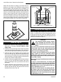
Install the Vent Pipe
Apply a bead of sealant around bottom end of inner starter pipe (found in bag with logset) and attach to stove. Apply a bead of sealant around top of inner starter pipe and
install the FSDHAG Draft Hood according to Draft Hood
instructions. (Fig. 33)
19
Oxford Direct Vent / Natural Vent Gas Heater
Attach the first section of venting to the draft hood. Depending on the length of the individual venting sections
and the lengths of the decorative pipe (if installed), you
may need to slip the decorative pipe over the venting sections before attaching upper sections to lower ones. The
sections of decorative pipe should be oriented with their
seams (if any) toward the wall; sections usually do not
need to be fastened at each joint, other than slip sections.
If the layout includes a slip section, this should be the last
section of pipe visible in the room, at the ceiling. Complete
the venting according to the vent maker’s instructions.
Left Log
Rear Log
Right Log
Decorative Grate
LG141
Fig. 34 Install the back, left and right logs.
Connect the Gas Supply Line
ENT
CEM
ST767
Fig. 33 Install draft hood adapter.
Install the Log Set
1.Remove the logs from their packaging, and inspect
ST767
each piece for damage. DO NOT INSTALL DAMDW
AGED LOGS.
draft hood
2. Install the attach
rear log centering
it side to side on the sheet
5/15/03
metal shelf at the backdjt
of the firebox. (Fig. 34) The log
will touch both sides and the back wall of the firebox.
3. Install the right log by engaging hole on bottom with
pin on the rear log. (Fig. 34) Then set right bottom side
on the burner so the edge of the log touches the right
side of the firebox. The right log does not use the locator pins on the burner to stay in place.
4. Install the left log by engaging hole on bottom with pin
on rear log. (Fig. 34) Then set left bottom side on the
burner so the edge of the log touches the left side of
the firebox.
5. Loosely sprinkle the lava rocks directly on top of the
burner in front of and between the decorative grate
and the right and left logs. Use the lava rock to cover
brackets on the burner. (Fig. 35)
20
Check the Rating Plate attached by a steel cable to the
firebox, to confirm that you have the appropriate firebox
for the type of fuel to be used. The Oxford may be converted from one gas to another using the appropriate Fuel
Conversion Kit listed LG141
on Page 34.
Stardance
Install logs 1
CAUTION
12/11/00
djt
This appliance should only be connected by a qualified gas technician. Test to
confirm manifold pressures as specified
below.
The heater and its individual shutoff valve must be
disconnected from the gas supply piping during
any pressure testing of that system at test pressures in excess of 1/2 psig (3.5 kPa).
The heater must be isolated from the gas supply
piping system by closing its individual manual
shutoff valve during any pressure testing of the
gas supply piping system at test pressure equal to
or less than 1/2 psig.
There must be a gas shutoff between the stove and
the supply.
In order to connect Natural Gas, use a fitting with
3/8” NPT nipple on the valve side and 1/2” natural
gas supply line with an input of 28,000 BTUs at a
manifold pressure of 3.5” and minimum inlet supply for adjustment of 5.5” w.c.
In order to connect Propane, use a fitting with 3/8”
NPT nipple on the valve side and 1/2” propane gas
supply line with an input of 28,000 BTUs at a manifold pressure of 10.0” and minimum inlet supply
for adjustment of 11.0” w.c.
20306762
Oxford Direct Vent / Natural Vent Gas Heater
In the U.S.; Gas connection should be made in accordance with current National Fuel Gas Code, ANSI Z223.1/
NFPA 54. Since some municipalities have additional local
codes, be sure to consult your local authority.
In Canada; consult the local authority and CSA-B149.1
installation code.
Always check for gas leaks with a mild soap
and water solution. Do not use an open flame
for leak testing.
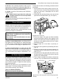
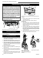
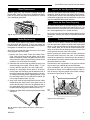
To adjust the air shutter, the following procedures should
be followed:
1. Remove barrier screen first by pulling out and up. Remove stove front. Lift stove front up and then swing
bottom out and away to disengage from the stove
body. (Fig. 36)
2. Swing open the swiveling latches at the top left and
right corners of the glass frame. (Fig. 59, Page 31)
Light the pilot according to the directions on Page 25, before going to the next step.
Burner Information
The appliance must only use the gas specified on the rating plate, unless converted using a Fuel Conversion Kit.
To convert from LP to Natural Gas use Kit #30005155. To
convert from Natural Gas to LP use Kit #30005154.
Conversion instructions are provided with each kit and
beginning on Page 27 in this manual.
This appliance should be connected to the gas
supply only by a qualified gas service technician.
Follow all local codes.
There must be a gas shut-off between the stove
and the supply.
In order to connect Natural Gas, use a fitting with 3/8”
NPT nipple on the valve side and 1/2” natural gas supply
line with an input of 28,000 BTUs at a manifold pressure
of 3.5” and minimum inlet supply for adjustment of 5.5”
w.c.
In order to connect Propane, use a fitting with 3/8” NPT
nipple on the valve side and 1/2” propane gas supply line
with an input of 28,000 BTUs at a manifold pressure of
10.0” and minimum inlet supply for adjustment of 11.0”
w.c.
Air Shutter Adjustment
The Oxford is shipped from the factory with the air shutter adjusted to the minimum allowed opening. Refer to
Table 1. Based on the altitude where the stove is located,
a shutter adjustment is acceptable to provide a mixed balance of flame color/glow. To adjust the shutter opening,
follow the steps below.
Fig. 36 Remove stove front.
3.Pull the top edge of the glass and frame assembly
away from the firebox, and lift it off its supports on the
ST1125 face. Place the assembly out of
bottom of the firebox
frontsurface such as a counter
the way on a remove
flat, padded
protected by a towel.
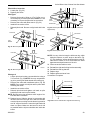
4. Take the logset out of the firebox if previously installed.
5. Remove the rear log bracket by unfastening the screw.
(Fig. 37)
6.Remove the right and left log bracket assembly by
unfastening the two screws which hold the burner in
place. (Fig. 37)
7. Hold the burner at the right hand side and lift to clear
the right burner leg. Then pull to the right to clear the
injectors on the left hand side.
8. The air shutter is located on the bottom of the burner
to the left. (Fig. 37) Unfasten the two nuts holding the
Remove Screws
Rear Log Bracket
Pilot
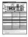
NOTE: The air shutter may only be adjusted to a more
open position. The factory setting is the minimum allowable air shutter opening. (Figs. 38 & 39)
Table 1. Air Shutter Adjustment
Minimum rear injector inlet openings.
Model
Direct Vent
Natural Vent
20306762
Natural Gas
1/2”
1/2”
LP
1/2”
1”
Left & Right Log
Bracket Assembly
Fig. 37 Remove rear log bracket and left and right log bracket
assembly.
ST350
Jefferson
air shutter adj
21
Oxford Direct Vent / Natural Vent Gas Heater
shutter in place. The shutter may be adjusted between
the factory adjusted 1/2” to fully open. Reassemble the
shutter to allow the rear injector air inlet to close from
the minimum 1/2” opening to fully open. (Fig. 39) You
may have to try more than once to find the correct air
shutter opening for best results depending on your altitude.
9. Refasten the two nuts and assemble the burner into
the unit by sliding the burner in at an angle with the
See Table 1
Left Burner Leg
Injector Shoulder
90¡
Air Shutter
(Original Position)
Burner
ST353
Fig. 40 Be sure to maintain 90° angle at left burner leg.
Complete the Assembly
ST352
Fig. 38 Air shutter in original from-the-factory position.
Front Injector
Air Inlet
Air Shutter
ST352
(May be adjusted up to fully open)
jefferson Burner
air shutter
new position
3/20/00 djt
Install ON/OFF Switch
The switch assembly parts are found in the parts bag.
Rear Injector Air Inlet
ST351
Fig. 39 Air shutter adjusted.
1. Attach switch assembly to left rear side of stove shroud
(when facing shroud) using two screws and existing
holes in shroud. (Fig. 41)
2. Run wires down back of stove, under bottom of rear
shroud to valve.
3. Attach wires to valve terminals. (Fig. 42)
Existing Holes
Switch Assembly
Screws
ST315
Fig. 41 Attach switch assembly to rear shroud.
PILOT
ADJ
TPTH
TP
ST315
attach switch assy
1/31/00 djt
TH
left side lower than the right side. Slide the left side
ST351
onto the injectors. Lower the
right hand side down into
jefferson
place. Make sure the burner
is as far left as possible
and the injector shoulders air
areshutter
inside the burner. NOTE:
It is very critical to keep theoriginal
left burner
leg, which holds
position
the injectors, at a 90° angle
to
the
base.
3/20/00 djt (Fig. 40) This
keeps the orifices aligned with tubes on the inside of
the burner. Failure to do so could affect the flame appearance and performance of the unit.
10.Refasten the right and left log bracket assembly.
11.Refasten the rear log bracket.
12.Replace logs.
13.Replace glass and stove front.
Follow lighting instructions on Page 25. Check flame color
appearance. NOTE: Allow stove to burn for at least 1/2
hour to establish full flame color.
Should color need further adjustment, repeat steps 1
- 12 for air shutter adjustment.
22
• Open the swiveling latches (cams) on the top left and
right corners of the glass frame.
• Position the glass and frame against the firebox by
placing the bottom edge on the brackets on the bottom
face of the firebox.
ST353
• Swing the assembly against
the firebox,
air shutter
adjust and close the
replace
latches firmly against theburner
pins protruding
from the fire3/20/00 djt
box top.
ST228
Fig. 42 Attach switch wires to valve.
ST228
attach switch
wires to valve
20306762
Oxford Direct Vent / Natural Vent Gas Heater
Thermostat Connection (optional)
Use only a thermostat rated for 500 millivolts.
Check the table below for the appropriate gauge thermostat wire to use for the length of lead required in your installation.
Thermostat
Wire / Gauge
18
16
14
3/8” Locking
Nut
Maximum Run
20 feet
20 - 40 feet
up to 60 feet
1. Install the wall thermostat in the desired location and
run the wires to the stove location. Terminate these
leads with 1/4” female connectors.
2. Connect the thermostat wires to the valve. (Fig. 42)
Install the Stove Front
Insert the handle stub into the hole in the front casting.
Fasten in place witht he 3/8” locking nut provided. (Fig.
43)
Handle Stub
ST773
Fig. 43 Insert handle stub into hole in front. Secure with 3/8”
locking nut.
Engage steel tabs behind
the cast iron bosses
ST773
handle assy
6/6/03
The front attaches to the stove by four steel tabs that engage with corresponding cast ribs onto the sides and bottom of the stove body. Position the front about 3” down
from stove top and lift the plate to engage the upper tabs
behind the adjacent ribs on the sides. (Fig. 44) Then lower
the front into position, so the lower tabs engage with the
corresponding ribs at the bottom.
When properly installed, the bottom of the stove front cannot be pulled away from the sides without also lifting it.
Bottom tabs engage
notch in the leg
ST1126
Fig. 44 Install the front plate.
ST1126
install stove front
20306762
23
Oxford Direct Vent / Natural Vent Gas Heater
CERTIFIED
SAFETY BARRIER
DANGER
HOT GLASS WILL
CAUSE BURNS.
DO NOT TOUCH GLASS
UNTIL COOLED.
Safety Barrier Installation Instructions
NOTE: A barrier designed to reduce the risk of burns
from the hot viewing glass is provided with this
appliance and shall be installed for the protection of
children and other at risk individuals. If the barrier
becomes damaged, the barrier shall be replaced with
the manufacturer's barrier for this appliance.* Any
safety screen, guard, or barrier removed for servicing
the appliance must be replaced prior to operating the
appliance.
* See parts list for model number.
The safety barrier has been designed to work with the
doors open or closed.
NEVER ALLOW CHILDREN
TO TOUCH GLASS.
A barrier designed to reduce the risk of burns from the hot
viewing glass is provided with this appliance and shall
be installed for the protection of children and
other at risk individuals.
20306543
WARNING: The safety screen barrier
must be installed after the glass front is
in place. It is NOT a replacement for the
glass and the unit must NOT be operated without the glass in place.
1. Remove screen from packaging.
2. Place the two bottom hooks over the bottom edge of
the stove opening. Figure 45
3. Press the screen against the stove snapping the two
spring fingers under the lattice until the screen fits
securely in place.
NOTICE: It is the responsibility of the installer to ensure
the barrier is affixed to the stove at the time of installation.
Spring fingers
Figure 45Safety Barrier Installation
24
Hooks
20306762
Oxford Direct Vent / Natural Vent Gas Heater
Operation
Flame & Temperature Adjustment
Read these instructions carefully and familiarize yourself
with the burner controls. Locate the pilot assembly, Figure
46. Follow the lighting instructions on Page 25 exactly.
For stoves equipped with HI/LO valves, flame adjustment
is accomplished by rotating the HI/LO adjustment knob
located near the center of the gas control valve. (Fig. 47)
During the first fire, it is not unusual to smell some odor
associated with new logs, paint and metal being heated.
Odors should dissipate within an hour or so, however, you
can open a window to provide fresh air to alleviate the
condition.
Pilot and Burner Inspection
Each time you light your heater check that the pilot flame
and burner flame patterns are as shown in Figure 48. If
flame patterns are incorrect, turn the heater off. Contact
your dealer or a qualified gas technician for assistance.
Do not operate the heater until the pilot flame is correct.
Follow regular maintenance procedures as described on
Page 30.
Turn
counterclockwise
to decrease
flame height
LO
Your First Fire
HI
Turn clockwise
to increase
flame height
Fig. 47 Flame adjustment knob for Honeywell valve.
Flame Characteristics
It is important to periodically
HV102 perform a visual check of
the pilot and the burner flames.
HoneywellCompare
hi/lo knob them to Figure
47. If any of the flames 4/5/99
appeardjtabnormal, call a service
person.
CO106c
Pilot Assembly
ST769
Fig. 46 Pilot assembly location.
ST769
Dutchwest
pilot location
5/15/03 djt
Red
Glow
Fig. 48
20306762
CO105c
Correct pilot and burner
flame patterns.
Pilot flame
4/10/00 djt
LG142
Stardance
Install logs 2
12/11/00 djt
LG143
25
Oxford Direct Vent / Natural Vent Gas Heater
Lighting and Operating Instructions
FOR YOUR SAFETY READ BEFORE LIGHTING
WARNING:If you do not follow these instructions exactly, a fire or explosion
may result causing property damage, personal injury or loss of life.
A. This heater has a pilot which must be lit manually. When
lighting the pilot follow these instructions exactly.
B. BEFORE LIGHTING smell all around the heater area
for gas. Be sure to smell next to the floor because
some gas is heavier than air and will settle on the
floor.
WHAT TO DO IF YOU SMELL GAS
• Do not try to light any fireplace
• Do not touch any electric switch
• Do not use any phone in your building
• Immediately call your gas supplier from a
neighbor’s phone.
Follow the gas supplier’s instructions.
• If you cannot reach your gas supplier, call the
Fire Department
C.Use only your hand to push in or turn the gas control
knob. Never use tools. If the knob will not push in or
turn by hand, do not try to repair it, call a qualified
service technician. Applying force or any attempted
repair may result in a fire or explosion.
D.Do not use this fireplace if any part has been under
water. Immediately call a qualified service technician
to inspect the heater and to replace any part of the
control system and any gas control which has been
under water.
Lighting Instructions
1. STOP! Read the safety information above.
2. Turn off all electrical power to the fireplace.
3. Turn the ON/OFF switch to “OFF” position, set the
remote to OFF or set thermostat to lowest level.
4. Open control access panel.
5. Push in gas control knob slightly and turn clockwise
to “OFF”.
3/8" - 1/2"
OT
ON P
IL
OF F
OFF
OF F
OF F
ON
1 2
P ilot
P IL O T
10. Push the control knob all the way in and hold. Immediately light the pilot by repeatedly depressing the
piezo spark ignitor until a flame appears. Continue
to hold the control knob in for about one (1) minute
after the pilot is lit. Release knob and it will pop back
up. Pilot should remain lit. If it goes out, repeat steps
5 through 8.
3 4 5
• If knob does not pop up when released, stop
and immediately call your service technician or
gas supplier.
Remove glass door before lighting pilot. (See Glass
•
If after several tries, the pilot will not stay lit,
FP1068
Frame Removal section).
FP1067
turn the gas control knob to “OFF” and call your
Lighting
instructions
lighting
instruction
Wait five (5) minutes
to clear
out any gas. Then smell
service technician or gas supplier.
Pilots
knobs
for gas, including near the floor. If you smell gas,
3/9/01 djt
11.
Replace
glass door.
STOP! Follow “B” in the safety information above. If
12.
Turn
gas
control knob to “ON” position.
you do not smell gas, go to the next step.
13.Turn
the
ON/OFF switch to “ON” position or set
Visibly locate pilot by the main burner.
thermostat
to desired setting.
Turn knob on gas control counterclockwise
to
14.
Turn
on
all
electrical
power to the fireplace.
“PILOT”.
SIT NOVA
6.
7.
8.
9.
To Turn Off Gas To Heater
1. Turn the ON/OFF switch to Off position or set the
thermostat to lowest setting.
2. Turn off all electric power to the fireplace if service
is to be performed.
26
3. Open control access panel.
4. Push in gas control knob slightly and turn clockwise
to “OFF”. Do not force.
5. Close control access panel.
20306762
Oxford Direct Vent / Natural Vent Gas Heater
Troubleshooting the Gas Control System
SIT NOVA 820 MILLIVOLT VALVE
NOTE: Before trouble shooting the gas control system, be sure external gas shut off is in the “On” position.
Symptom
Possible Causes
Corrective Action
1. Spark ignitor will not light
A. Defective or misaligned electrode
at pilot
Using a match, light pilot. If pilot lights, turn off pilot and
push the red button again. If pilot will not light - check
gap at electrode and pilot-should be 1/8” to have a strong
spark.
B. Defective ignitor (Push Button)
2. Pilot will not stay lit after
carefully following lighting
instructions
3. Pilot burning, no gas to
main burner
4. Frequent pilot outage
problem
20306762
With the control knob in the pilot position, push the control
knob all the way and hold. Check for spark at electrode
and pilot. If no spark to pilot, and electrode wire is properly
connected, replace the battery in the ignitor module and
try again. Refer to Maintenance Section. If the problem
still exists, replace the ignitor module box.
A. Defective pilot generator (thermocouple), remote wall switch
Check pilot flame. Must impinge on thermocouple/thermopile. NOTE: This pilot burner assembly utilizes both
a thermocouple and a thermopile. The thermocouple
operates the main valve operation (On and Off). Clean
and or adjust pilot for maximum flame impingement on
thermopile and thermocouple.
B. Defective automatic valve
Turn valve knob to “Pilot”. Maintain flow to pilot; millivolt
meter should read greater than 10mV. If the reading is
okay and the pilot does not stay on, replace the gas valve.
NOTE: An interrupter block (not supplied) must be used
to conduct this test.
A. Wall switch or wires defective
Check wall switch and wires for proper connections.
Jumper wire across terminals at wall switch, if burner
comes on, replace defective wall switch.. If okay, jumper
wires across wall switch wires at valve, if burner comes
on, wires are faulty or connections are bad.
B. Thermopile may not be generating sufficient millivoltage
1. Be sure wire connections form thermopile at gas valve
terminals are tight and thermopile is fully inserted into
pilot bracket.
2. One of the wall switch wires may be grounded. Remove wall switch wires form valve terminals if pilot
now stays lit, trace wall switch wiring for ground. May
be grounded to fireplace or gas supply.
3. Check thermopile with millivolt meter. Take reading
at thermopile terminals of gas valve. Should read
250-300 millivolts (minimum 150) while holding valve
knob depressed in pilot position and wall switch “Off”.
Replace faulty thermopile if reading is below specified
minimum.
C. Plugged burner orifice
Check burner orifices for debris and remove.
D. Defective automatic valve operator
Turn valve knob to “On”, place wall switch to “On” millivolt
meter should read greater than 150mV. If the reading is
okay and the burner does not come on, replace the gas
valve.
A. Pilot flame may be too low or
blowing (high) causing the pilot
safety to drop out
Clean and/or adjust pilot flame for maximum flame impingement on thermopile and thermocouple.
B. Possible blockage of the vent
terminal
Check the vent terminal for blockage (recycling the flue
gases).
27
Oxford Direct Vent / Natural Vent Gas Heater
Fuel Conversion Instructions
OFF
O H
PILOT
ADJ
ON P
IL
L
I
OT
CAUTION: The gas supply shall be shut off prior
to disconnecting the electrical power, before proceeding with the conversion.
Gas Supply Inlet
Main Gas
Line
Fig. 49 Attach the gas line to the left side of the valve.
Conversion Precautions
Before proceeding, turnST770
control knob on valve to OFF and
turn gas supply OFF. Turn OFF any electricity that may be
DW
going to the appliance.
Remove Screws
Pilot
Left & Right Log
Bracket Assembly
Fig. 50 Remove rear log bracket and left and right log bracket
assembly.
8. Remove injectorST350
orifices from left burner leg using
1/2” wrench. (Fig. 55)
Jefferson
9. Install conversionair
orifices.
shutter(Refer
adj to Table 2)
SIT 820 Valve
3/20/00 djt
1. Using TORX T20 bit, remove and discard the three
(3) pressure regulator mounting screws (A), pressure
regulator tower (B) and the spring and diaphragm assembly (C). (Fig. 51)
2. Insure the rubber gasket (D) is properly positioned
and install the new HI/LO pressure regulator assembly to the valve using the new screws (E) supplied
with the kit. Tighten the screws securely. (Ref. torque
= 25 in/lb) (Fig. 52)
3. Install the enclosed conversion label (F) to the valve
body where it can easily be seen. (Fig. 52)
A
attach gas line
5/15/03
djt
Conversion
Procedure
E
B
C
IL
FP
OF
O
D
OF
FP
IL
OT
O
1. Remove stove front. Lift stove front up and then
swing bottom out and away to disengage from the
stove body. (Fig. 59, Page 30)
2. Swing open the swiveling latches at the top left and
right corners of the glass frame. (Fig. 59, Page 31)
3. Pull the top edge of the glass and frame assembly
away from the firebox face. Place the assembly out of
the way on a flat, padded surface such as a counter
protected by a towel.
4. Remove the logset from the firebox.
5. Remove the rear log bracket by unfastening the
screw. (Fig. 50)
6. Remove the right and left log bracket assembly by
unfastening the two screws which hold the burner in
place. (Fig. 50)
7. Hold the burner at the right hand side and lift to clear
the right burner leg. Then pull to the right to clear the
injectors on the left hand side.
28
Rear Log Bracket
OT
WARNING! This conversion kit shall be installed
by a qualified service agency in accordance with
the manufacturer’s instructions and all applicable
codes and requirements of the authority having jurisdiction. If the information in these instructions is
not followed exactly, a fire, explosion or production
of carbon monoxide may result causing property
damage, personal injury or loss of life. The qualified service agency is responsible for the proper
installation of this kit. The installation is not proper
and complete until the operation of the converted
appliance is checked as specified in the manufacturer’s instructions supplied with the kit.
F
Fig. 51 Remove mounting
screws, pressure regulator
tower and spring and diaphragm
assembly. FC107
SIT820
valve conversion
10/03
FC108
Fig.
52 Replace regulator.
SIT
regulator
conversion
10/03
20306762
Oxford Direct Vent / Natural Vent Gas Heater
Pilot Orifice Conversion
1. Locate pilot. (Fig. 50)
2. Replace pilot orifice.
Pilot Type 1
• Remove pilot hood by lifting up. (Fig. 53) Do not remove snap ring to remove pilot hood. NOTE: It is not
necessary to remove the pilot tube for conversion.
• Remove pilot orifice with allen wrench. (Fig. 54)
• Install the conversion orifice.
• Reinstall pilot hood. Be sure to align hood with index
tab.
Pilot
Index
Marks
Pilot Bracket
CO105
Fig. 55 Remove pilot hood. (Your pilot may have a different
appearance).
CO105
Pilot Orifice
Gas Conversion
Pilot
2/15/99 djt
Pilot Hood
Pilot
Bracket
CO105a
Fig. 53 Remove pilot hood.
CO106b
Fig. 56 Remove pilot orifice.
Index Tab
Snap Ring
Allen Wrench
CO105a
gas conversion
Pilot
1/28/00 djt
CO106a
Fig. 54 Remove pilot orifice.
Pilot type 2
CO106a
DV360/580
• Loosen pilot hood
turning counterclockwise using a
Gas55)
Conversion
7/16” wrench. (Fig.
NOTE: You may use penetratPilot2
ing oil to prevent1/28/00
pilot hood
djtthreads from seizing up.
• Remove pilot orifice with needlenose pliers. (Fig. 56)
NOTE: Use a wrench to hold pilot tube in place while
removing the orifice.
• Install the conversion orifice.
• Reinstall pilot hood and tighten until mark on pilot
hood aligns with mark on pilot bracket.
NOTE: Be sure burner leg remains at a 90° angle to firebox base after conversion.
21. Replace burner. Slide the burner in at an angle with
left side lower than the right side. Slide the left side
onto the injectors, making sure the burner leg remains
at a 90° angle to the base. Lower the right hand side
down in to place. Make sure the burner is as far left
as possible and the injector shoulders are inside the
burner.
20306762
NOTE: It is very critical to keep the left burner leg, which
CO106a
holds the injectors, at a 90° angle to the base. (Fig.
Gas Conversion
57) This keeps the orifices aligned with the tubes in(Vermont)
side burner. FailurePilot
to do
so could affect the flame
7/19/99
djtof the unit.
appearance and performance
22. Place conversion label on valve.
23. Reinstall the right and left log bracket assembly.
24. Reinstall the rear log bracket.
25. Replace logs.
26. Replace glass and stove front.
Conversion is complete.
Left Burner Leg
Injector Shoulder
90¡
ST353
Fig. 57 Be sure to maintain 90° angle at left burner leg.
ST353
air shutter adjust
burner replace
3/20/00 djt
29
Oxford Direct Vent / Natural Vent Gas Heater
Table 2. Injector Orifice Size Matrix
Kit #
30005155
Conversion to Natural Gas
Front
Part #
Rear
#54 / .055" 30000514
#44 / .086”
Part #
30000334
Input (BTU/h)
Minimum
Maximum
19,000
28,000
Conversion to LPInput (BTU/h)
Kit #
Front
Part #
Rear
Part #
Minimum
Maximum
30005154
#69 / .029" 30000513
#54 / .055” 30000514
20,000
28,000
Maintenance
Your gas heater will provide years of service with minimal
upkeep. The following procedures will help ensure that
your stove continues to function properly.
Annual System Inspection
Have the entire heater and venting system inspected annually by a qualified gas technician. Replace any worn or
broken parts.
Logset and Burner /
Cleaning and Inspection
Cleanliness is critical to the proper function of the heater.
The logset and burner must all be kept free of dust and
unobstructed by debris. Inspect these areas before each
use and clean as necessary.
1. Turn the burner OFF and let the heater cool completely
before cleaning.
2. Remove the safety barrier by pulling out, then up.
3. Lift the stove front up and then swing the bottom out to
disengage it from the heater shell. (Fig. 58)
4. Carefully remove the glass and frame assembly and
place it out of the way on a flat, padded surface such
as a counter protected by a towel.
CAUTION
TURN THE PILOT OFF BEFORE PAINTING. ALLOW
THE HEATER TO COOL COMPLETELY BEFORE
PAINTING.
6. Use a soft bristled brush to sweep dust or debris from
the Logs, Pilot and Burner. Use care as the logs are
fragile and susceptible to damage. DO NOT USE A
VACUUM TO CLEAN THE LOGS OR BURNER.
7. Replace the glass panel and frame assembly.
8. Replace the Stove Front.
Care of Cast Iron
An occasional dusting with a dry rag will help keep the
painted surfaces looking new. Use high-temperature
stove paints, available through your local dealer, to touchup areas as needed. Clean areas to be painted with a
wire brush and be sure to cover the logs, burner and valve
assembly, glass and frame assembly. Apply the paint
sparingly; two light coats of paint will give better results
than a single heavy coat.
Clean porcelain enamel surfaces with a soft, damp cloth.
Do not use abrasive cleaning agents. If necessary, use
only a cleaning agent formulated especially for use on
porcelain enamel surfaces.
Cleaning the Glass
WARNING: Allow the glass cool completely
before attempting to clean.
Fig. 58 Remove the stove front.
5. Carefully inspect the Logs for damage. Contact your
local dealer if any
damage is evident. DO NOT OPERST1125
ATE THE HEATER
WITH
remove
frontDAMAGED LOGS.
30
It will be necessary to clean the glass periodically. During
start-up, condensation, which is normal, forms on the inside of the glass and causes lint, dust and other airborne
particles to cling to the glass surface. Also initial paint
curing may deposit a slight film on the glass. It is therefore recommended that the glass be cleaned two or three
times with a non-ammonia household cleaner and warm
water (we recommend gas fireplace glass cleaner). After
that the glass should be cleaned two or three times during
each heating season depending on the circumstances
present.
Clean glass after first two weeks of operation.
20306762
Oxford Direct Vent / Natural Vent Gas Heater
Glass Replacement
Inspect the Vent System Annually
Replace glass only with Vermont Castings Group approved parts. Refer to Page 33 for Replacement Parts.
Refer to Figure 59 and previous instructions for removal
of the damaged glass frame.
Have the vent system inspected annually by a qualified
technician. Shut off the main gas supply before inspecting the system. Both the inner exhaust pipe and the outer
combustion supply pipe must be checked to confirm that
they are unblocked and in good condition.
Check the Gas Flame Regularly
To ensure that the stove is operating properly, check the
flames periodically to confirms they match Figure 60. The
flames will be blue during the first 15-20 minutes of operation, and will gradually turn to yellow after that.
Fig. 59 Release the latches to release the glass frame.
Do not use your stove if the flame pattern differs from that
shown here. Contact your dealer or a qualified technician
for help.
Gasket Replacement
Stove Disassembly
The heater uses a ‘tadpole’ type gasket to seal between
the glass panel and the frame. In time, this gasket can
become brittle and compressed and should be replaced.
New gasket is available from your dealer.
If there is ever a need to remove the firebox assembly
from the stove shell, support the firebox with solid stands
about 6” (150 mm) tall under the left and right outer edges
of the firebox base. Do not set the firebox assembly directly on the floor; this can damage the control valve and/
or the gas lines from the valve to the firebox.
Shut off the gas supply and allow the stove to cool. Wear
safety goggles and a dust mask.
1.Remove the Front, Glass Frame and Glass Panel.
(Figs. 59 & 60) Remove the old gasket. Use a razor
ST208 the glass and gasket from the frame,
blade to separate
glass
latch
and to clean
theswivel
glass of
any remaining cement or bits
of gasket.12/99
Use a cold chisel if necessary.
2. Determine the correct length of gasket by laying it out
around the edge of the glass. Allow an extra 1 - 2” (2550 mm). Mark the spot to be cut. Use a utility knife.
3. Starting on a long edge, remove about 6” of the protective paper strip and apply the flat adhesive face of
the gasket around the outside-facing edge of the panel. Continue around the panel, applying a bout 6” at a
time and being careful to not stretch the material. Do
not overlap the gasket ends. (Fig. 60)
4. Apply a thin bead of high temperature silicone rubber
sealant along the inside corner of the glass frame, all
around the perimeter. Place the flat gasketed side of
the glass panel back into the steel frame. Pinch the
rounded inside-facing gasket material to bulk it up.
5. Replace the glass frame and front panel as previously
described.
Before removing the firebox from the shell, disconnect
the on/off switch wires from the valve. If the assembly
includes the optional fan, disconnect the fan rheostat. If
the installation includes a wall thermostat, disconnect the
thermostat leads from valve.
Disconnection and reconnection to the gas line should
only be done by a qualified gas service technician.
Upon reinstallation, the vent system must be sealed to
the firebox as shown in the installation section, Page 16.
Also be sure the logs are placed in the firebox correctly,
as shown in Figures 34 & 35, Page 20.
Red
Glow
Fig. 61 Correct flame pattern.
Fig. 60 Wrap the gasket material around the outside edge of
the glass.
20306762
ST179
glass gasket detail
11/99
31
LG142
Oxford Direct Vent / Natural Vent Gas Heater
Wiring Diagrams
OFF
On/Off Switch Wiring
Thermopile
Black
BL
Millivolt
Gas Valve
TP
K
GRN
BL
K
ST124b
Thermostat
Black
Optional Thermostat
(Optional)
Wiring
TH
Chassis
Ground
Black
TH
TP
BLK
WHT
TP/TH
St124b
on/off/switch
wiring
1/11/00Blackdjt
BLK
FAN JUNCTION BOX
Thermostat
(Optional)
Strain Relief
Thermopile
TP/TH
FAN
POWER
CORD
ON
ON / OFF
Rheostat
Millivolt
Gas Valve
ST124c
Snapstat
Fig. 62 On/Off switch and optional thermostat circuit.
LK
WHT
BLK
B
NOTE: IF ANY OF THE ORIGINAL WIRE, AS SUPPLIED WITH THE APPLIANCE, MUST BE REPLACED, IT MUST BE REPLACED WITH TYPE SF-2,
200° WIRE OR ITSSt124c
EQUIVALENT.
Thermostat
wiring
1/11/00
djt
Safety Limit
GRN
Chassis Ground
RHEOSTAT / SNAPSTAT
BOX
ST153
Switch
Schematic Diagram
BLK
BLK
Thermocouple
MOTOR
Valve
ST153
rdv connections diag.
BLK
10/99
WHT
ST665
GRN
WHT
BLK
SNAPST AT
ON/OFF
RHEOST AT
Fig. 63 Draft hood adapter
wiring.
ST665
Safety Limit
Switch wiring
5/29/01 djt
ST236
Fig. 64 Fan circuit.
ST236
FK26 wiring diagram
12/99
32
20306762
Oxford Direct Vent / Natural Vent Gas Heater
Replacement Parts
2
1
7
3
6
4
1a
1c
5
1b
12
10
16
21
40
13
14
9
11
18
22
17
23
19
20
27
25
24
28
26
31
29
32
33
30
36a,b
35
C
34
15a,b,
c,d
NT
E
EM
8
37
Vermont Castings Group reserves the right to make changes in design, materials, specifications, prices and discontinue colors and products at any
time, without notice.
Ref. Description
1. Gas Log Assembly - SDV30
1a. Rear Log
1b. Right Log
1c. Left Log
2. Small Lava Rock Package
3.Top
4.Front
5.Door
6. End, Rt
7. End, Lt 8.Leg
9. Manifold Assembly
20306762
5123
Oxford parts
Oxford
20003458
20003459
20003460
20003461
57897
30001925
30001928
30001929
30001927
30001926
30001930
20003739
33
Oxford Direct Vent / Natural Vent Gas Heater
Replacement Parts (continued)
Ref.
10.
11.
12.
13.
14.
15a.
15b.
15c.
15d.
16.
17.
18.
19.
20.
21.
22.
23.
24.
25.
26.
27.
28.
29.
30.
31.
32.
33.
34.
35.
36a.
36b.
37.
38.
39.
40.
Description
Glass, DV25
Glass Frame Assembly - SDV30
Gasket, Glass - Med. Knit - RDV40
Pilot Top Convertible
Pilot Assembly 3Way N/DV RN 0.199.706
Pilot Assembly 3Way N/DV RP 0.199.703
Orifice Hood #69 - Front - LP
Orifice Hood #54 - Front - NG
Orifice Hood #54 - Rear - LP
Orifice Hood #44 - Rear - NG
Thermocouple 24” Thermopile 18” RS Electrode Ignitor w/Cable SIT24
Nut Electrode SIT #0.974.144
Tubing Pilot w/Fittings 1/8 x 24”
Burner Housing Assembly NG/LP
Grate, Burner - JDV
Ashdoor Handle Assy - E/V/WSI
Handle, Damper - Maple Wood - Blk
Switch ON/OFF - RN/RP Models
Wiring Harness - FSDV32 RN/JDV
Right Log Bracket
Left Log Bracket
Nut, Hex Jam 3/8 -16 TOPLK-Z
Gasket, Base Pan - JDV Gasket, Base Pan Inner Gasket Cement, 3 oz tube (not shown)
Gasket, HE Door
Sensor 2450 CMG-8184-0032
Pan Hd, SL 1/4-20 x 3-Z
Valve Nova SIT820.662 RN (Serial #’s starting with 6414)
Valve Nova SIT820.653 RP (Serial #’s starting with 6414)
Ignitor Piezo w/Nut SIT
Bracket Piezo Ignitor (not shown)
*Magnet, Control Door (not shown)
Safety Barrier
Oxford
1601691
30000127
1203702
10002266
10002264
10002265
30000513
20000130
20000130
30000334
24D0808
7533113
10001297
57886
10001296
20002214
20002167
5004241
1600664
30000874
10002582
20002166
20002165
1203290
20002282
20002566
1206122
1203687
10002013
1201310
20010563
20010645
057958
20010876
1408818
30007256
*Use common super glue or silicone to attach magnets.
Fuel Conversion Kits
Conversion Kit, NG to LP - OXDV30NV Kit #30005154
Conversion Kit, LP to NG - OXDV30PV Kit #30005155
34
20306762
Oxford Direct Vent / Natural Vent Gas Heater
Optional Accessories
Fan Kits
FK26 Fan
The FK26 fan helps distribute heated air from within
the firebox out into the room. The fan is controlled by a
snapstat that turns power on and off as the firebox temperature rises above and falls below a preset temperature. A rheostat provides for variable fan speeds.
Specifications
Remote Controls
The remote control allows you to turn the heater on or off
from anywhere in the room. Refer to Page 32 for wiring
diagrams.
Model Functions Controlled
RC1ON/OFF
RC2
ON/OFF and Temperature
IMTFK Wall mounted thermostat control
Decorative Rings
115 Volt / 60Hz / .75 Amps
Maintenance
The fan itself does not require regular maintenance, however, periodic cleaning of the fan and the surrounding
area is required.
Installation
7” brass or charcoal gray rings are available to add a decorative touch to the exposed stove pipe.
Model
7FSDRG/4
Description
7” Charcoal Gray Rings (4)
Refer to Page 14 for installation instructions.
20306762
35
Oxford Direct Vent / Natural Vent Gas Heater
36
20306762
Oxford Direct Vent / Natural Vent Gas Heater
20306762
37
Oxford Direct Vent / Natural Vent Gas Heater
38
20306762
Oxford Direct Vent / Natural Vent Gas Heater
LIMITED LIFETIME WARRANTY
PRODUCT COVERED BY THIS WARRANTY
All Vermont Castings Group gas stoves equipped with an Insta-Flame Ceramic Burner.
BASIC WARRANTY
Vermont Castings Group (hereinafter referred to collectively as the
Company) warrants that your new Vermont Castings Group Gas
Fireplace/Stove is free from manufacturing and material defects for a
period of one year from the date of purchase, subject to the following
conditions and limitations.
EXTENDED LIFETIME WARRANTY
The heat exchanger, where applicable, and combustion chamber
of every Vermont Castings Group gas product is warranted for life
against through wall perforation. All appliances equipped with an
Insta-Flame Ceramic Burner have limited lifetime coverage on the
ceramic burner plaque. Warrantees are made to the original owner
subject to proof of purchase and the conditions and limitations listed
on this Warranty Document
COMPONENT WARRANTY
CAST IRON: All external and internal cast iron parts are warranted for a
period of three years.
Note: On porcelain enamel finished external parts and accessories
The Company offers no Warranty on chipping of enamel surfaces. Inspect all product prior to accepting it for any damage to the enamel.
The salt air environment of coastal areas or a high humidity environment can be corrosive to the porcelain enamel finish. These conditions can cause rusting of the cast iron beneath the porcelain enamel
finish, which will cause the finish to flake off.
Dye lot variations with replacement parts and/or accessories can occur and are not covered by warranty.
GLASS DOORS: Glass doors are covered for a period of one year.
Glass doors are not warranted for breakage due to misuse or accident.
Glass doors are not covered for discoloration or burned in stains due to
environmental issues, or improper cleaning and maintenance.
BRASS PLATED PARTS AND ACCESSORIES: Brass parts should be
cleaned with Lemon oil only. Brass cleaners cannot be used. Mortar
mix and masonry cleaners may corrode the brass finish. The Company
will not be responsible for, nor will it warrant any brass parts which are
damaged by external chemicals or down draft conditions.
GAS VALVES: Gas valves are covered for a period of one year
ELECTRONIC AND MECHANICAL COMPONENTS: Electronic and
mechanical components of the burner assembly are covered for one
year. All steel tube burners are warranted for one year.
ACCESSORIES: Unless otherwise noted all components and Vermont
Castings Group company supplied accessories are covered for a period
of one year.
CONDITIONS AND LIMITATIONS
• This new Vermont Castings Group product must be installed by a
competent, authorized, service contractor. A licensed technician, as
prescribed by the local jurisdiction must perform any installation/service work. It must be installed and operated at all times in accordance with the Installation and Operating instructions furnished with
the product. Any alteration, willful abuse, accident, or misuse of the
product shall nullify this warranty.
• This warranty is non-transferable, and is made to the original owner,
provided that the purchase was made through an authorized supplier
of the Company.
• The customer must pay for any Authorized Dealer in-home travel fees
or service charges for in-home repair work. It is the dealers option
whether the repair work will be done in the customer’s home or in the
dealer’s shop.
• If upon inspection, the damage is found to be the fault of the manufacturer, repairs will be authorized at no charge to the customer parts
and/or labor.
20306762
• Any part and/or component replaced under the provisions of this warranty is covered for six months or the remainder of the original warranty, whichever is longest.
• This warranty is limited to the repair of or replacement of part(s) found
to be defective in material or workmanship, provided that such part(s)
have been subjected to normal conditions of use and service, after
said defect is confirmed by the Company’s inspection.
• The company may, at its discretion, fully discharge all obligations with
respect to this warranty by refunding the wholesale price of the defective part(s)
• Any installation, labor, construction, transportation, or other related
costs/expenses arising from defective part(s), repair, replacement, or
otherwise of same, will not be covered by this warranty, nor shall the
Company assume responsibility for same. Further, the Company will
not be responsible for any incidental, indirect, or consequential damages except as provided by law.
• SOME STATES DO NOT ALLOW FOR THE EXCLUSION OR LIMITATIONS OF INCIDENTAL AND CONSEQUENTIAL DAMAGES OR
LIMITATIONS ON HOW LONG AN IMPLIED WARRANTY LASTS,
SO THE ABOVE LIMITATIONS MAY NOT APPLY TO YOUR CIRCUMSTANCES. THIS WARRANTY GIVES YOU SPECIFIC RIGHTS
AND YOU MAY HAVE OTHER RIGHTS WHICH VARY FROM STATE
TO STATE.
• All other warranties-expressed or implied- with respect to the product,
its components and accessories, or any obligations/liabilities on the
part of the Company are hereby expressly excluded.
• The Company neither assumes, nor authorizes any third party to assume on its behalf, any other liabilities with respect to the sale of this
Vermont Castings Group product
• The warranties as outlined within this document do not apply to chimney components or other non Vermont Castings Group accessories
used in conjunction with the installation of this product..
• Damage to the unit while in transit is not covered by this warranty but
is subject to claim against the common carrier. Contact the dealer
from whom you purchased your fireplace/stove (do not operate the
appliance as this might negate the ability to process the claim with the
carrier).
• The Company will not be responsible for:
a) Down drafts or spillage caused by environmental conditions such
as near-by trees, buildings, roof tops, hills, or mountains.
b) Inadequate ventilation or negative air pressure caused by mechanical systems such as furnaces, fans, clothes dryers, etc.
• This warranty is void if:
a) The fireplace has been operated in atmospheres contaminated by
chlorine, fluorine, or other damaging chemicals.
b) The fireplace has been subjected to prolonged periods of dampness or condensation
c) Any damages to the fireplace, combustion chamber, heat exchanger or other components due to water, or weather damage, which is the
result of but not limited to, improper chimney/venting installation.
d) Any alteration, willful abuse, accident, or misuse of the product has
occurred.
IF WARRANTY SERVICE IS NEEDED…
1)Contact your supplier. Make sure you have your warranty, your
sales receipt, and the model/serial number of your Vermont Castings Group product.
2)DO NOT ATTEMPT TO DO ANY SERVICE WORK YOURSELF.
39
EFFICIENCY RATINGS
Model
EnerGuide Ratings Fireplace Efficiency (%)
OXDV30NV
63.0
Based on CSA P.4.1-09
Recherchez dans la brochure
les caractéristique de rendement
énergétique de foyer au gaz
Énerguide
Based
CSA
P.4.1-09
SelononCSA
P.4.1-09
149 Cleveland Drive • Paris, Kentucky 40361
www.vermontcastingsgroup.com