1
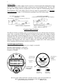
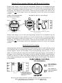
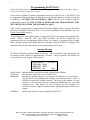
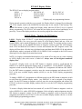
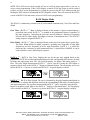
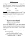
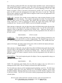
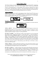
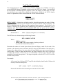
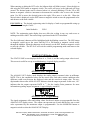
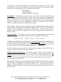
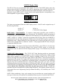
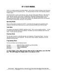
1 FLOW TRANSMITTERS ELECTRONICS FOR INSTRUMENTATION RT-Ex15-Ex Flow Monitor User Manual 8809 Industrial Drive, Franksville, WI 53126-9337 AW-Lake Company 8809 Industrial Drive, Franksville, WI 53126 web: www.awgearmeters.com Tel: 262-884-9800 Fax:262-884-9810 Tel: 262-884-9800 Fax: 262-884-9810 Email: [email protected] Web: http://www.awgearmeters.com E-Mail:RT-Ex15-Ex [email protected] manual rev 6.13.11.docx Revision 3.3.10 2 RT-Ex15-Ex FLOW MONITOR Introduction / Features…..………..……………………... Model Number/Sensor Options.……………………..….. Specifications…..………..…………………………..….. Dimensional Drawing.….………………………………. Hazardous Area Installation Instructions………………. Wiring Connections……….................…………………. DC Power Connection...........…………………... Reset Input……….................…………………... Limits/Pulse Output...............…………………... Analog Output……................…………………... Frequency Input (Calibration) Test Point.………. Display/Programming Buttons and Magnetic Switches… Disable External Programming....………………. Programming……………....…………….....…..……….. Startup Message…………...........………………. Display Modes………………….....…..………………… LOGO Mode – Turning On/Off Displays……..... RATE Display Modes..............………………….. RATE A GT .……................……………… RATE A PL .……................……………… RATE Mode Programming.............…………….. KFR A VALUE.................……………… GATE A B……..………….……………. SAMPLE A……………………………… ENG UNITS A……………………...…... TOTAL Display Modes.....…………………..…. TOTAL A Display…….……….….……. GR TOTAL A Display…….……...……. TOTAL Reset / Rollover…….…….……. TOTAL Mode Programming........................…… KFT A VALUE.…........…………….….. ENG UNITS A...….…..………………… STATUS ONE Display Mode.….……………... ANALOG OUT Display Mode.….……………... ANALOG OUT Programming.………………… MA OFFSET.…........………………..…. ANALOG POINT....…..………………... VALUE AT 20 MA……………………… LIMITS Display Mode...........…….……….……. LIMITS Programming…………………………… RATE/TOTAL limits……...…………….. CYCLE OUT (Totalizer Pulse Output)…. RATE & TOTAL Display Mode ....…………….. BATCH TOTAL Display Mode ....…………….. BATCH TOTAL Programming.......…………….. QUICK-GUIDE to Variables & Displays……………….. page 3 page 3 page 3 page 3 page 4 page 5 page 4 page 5 page 5 page 6 page 6 page 7 page 7 page 8 page 8 page 9 page 9 page 10 page 10 page 10 page 11 page 11 page 12 page 12 page 12 page 13 page 13 page 13 page 13 page 14 page 14 page 15 page 15 page 15 page 15 page 16 Page 15 Page 16 page 17 Page 17 Page 17 Page 17 page 18 page 19 page 19 page 20 AW-Lake Company 8809 Industrial Drive, Franksville, WI 53126 web: www.awgearmeters.com Tel: 262-884-9800 Fax: 262-884-9810 Email: [email protected] RT-Ex15-Ex manual rev 6.13.11.docx Revision 3.3.10 3 Introduction / Features The RT-Ex15-Ex is a meter-mounted digital flow monitor that is certified for use in Class I Div. 1 locations when mounted on an approved AW meter. A large, back-lighted LCD graphic display provides easy to read indication of flow rate or total in user programmable engineering units. Programming, display mode selection or reset of the totalizer is accomplished using an attached magnet without opening the enclosure or using the pushbuttons on the faceplate with cover off. An isolated input also allows for remote reset of the totalizer. Programmable opto-isolated NPN open-collector outputs provide flowrate limit indication or a pulsed total output for remote monitoring and recording of totals. A 4-20 mA rate output with user programmable filtering and scaling is also provided for remote indication. A variety of sensor noses are available to provide compatibility with all AW Gear Meters. RT-Ex15-Ex options: Swivel union available HART protocol available Specifications Power Requirement: (Customer supplied) Class 2, 24 VDC, 200mA min Sensor/Monitor Frequency Range: 0-4000 Hz. Analog Output 4-20 mA: 16-bit Isolated Loop Powered 2-Wire Output. 24 Vdc Loop Supply Max. Load Impedance 500 Ohm.@ 24V Max. Load Impedance 250 Ohm.@ 12V Two Opto-Isolated Open-Collector Outputs: 5-24 VDC Rating, 50 mA Max. (Minimum Load Impedance Required, 480 Ohm @ 24 VDC) Opto-Isolated Reset Input: 5-24 VDC Input, 3.3Kohm Impedance Temperature Ratings: Unit: -40 to 60ºC (-40 to 140ºF) Ambient : T6 60ºC (140ºF) Max. Fluid Temperature RT-Ex15-Ex Certifications: CSA: Class I, Division 1, Groups A, B, C, D Class II, Groups E, F, G; Class III Connection: Screw terminal strips ¾” NPT Conduit Entrance Input and output signals to be supplied by a Class 2 power supply RT-Ex15-Ex Dimensions AW-Lake Company 8809 Industrial Drive, Franksville, WI 53126 web: www.awgearmeters.com Tel: 262-884-9800 Fax: 262-884-9810 Email: [email protected] RT-Ex15-Ex manual rev 6.13.11.docx Revision 3.3.10 4 Special installation instruction for use in hazardous area environments Figure 1. RT-Ex15-Ex name plate The RT-Ex15-Ex unit is an explosion proof local display which may be used in Class I, Division 1 locations. Above is a sample of the name plate that should be clearly attached to each unit. Please make sure this name plate is on the unit and that the information matches what is shown above, prior to installation. Depending on whether the unit is equipped with a swivel union and/or installed with either a 303ss or 316ss flowmeter, the tag may not include the Type 4X rating. If either the name plate is not on the unit or the unit name plate does not match what is shown above, please notify AW-Lake Company and determine what needs to be done. Because the RT-Ex15-Ex uses an explosion proof enclosure for its area protection, power must be removed from the unit before the covers are removed while in a hazardous area. For proper installation, it is also necessary that the conduit entries are properly sealed. To maintain the units explosion proof certification, anything threaded into the NPT conduit openings must engage by a minimum of 5 full threads. Original units received from AW-Lake Company will have a sensor installed. This item is properly installed with a minimum of 5 full threads of engagement and should not be tampered with. The unit also comes with a blind plug. It is the customer’s responsibility to make sure that any blind plugs used are properly installed with a minimum of 5 full threads of engagement. NOTE: It is strongly suggested to use anti-seize grease on threads prior to installation to avoid galling. When installing the RT-Ex15-Ex into an AW spur gear meter, in order to maintain the unit’s explosion proof rating, make sure the 3/8” NPT male portion of the sensor is engaged by a minimum of 5 threads into the flowmeter. NOTE: It is strongly suggested to use anti-seize grease on threads prior to installation to avoid galling. When wiring the unit, please make sure to observe any national or local codes that may be required. An explosionproof seal is required within 18 inches (450mm) of the enclosure. If installed in a Class I, Division 2 area, an explosion-proof seal is still required within 18 inches (450mm) of the enclosure according to Class I, Division 1 installation requirements. Make sure units are powered by a Class 2 power supply for proper regulation. Removal of the external housing ground terminal is not permitted for safety reasons. Please make sure to follow local electrical code practices when installing equipment in hazardous areas. AW-Lake Company 8809 Industrial Drive, Franksville, WI 53126 web: www.awgearmeters.com Tel: 262-884-9800 Fax: 262-884-9810 Email: [email protected] RT-Ex15-Ex manual rev 6.13.11.docx Revision 3.3.10 5 Wiring Connections Wiring connections are to terminal strips inside the rear cover. A ¾” NPT wire exit for conduit connection is provided. Connection to conduit is required to maintain the enclosures explosionproof rating and must be made in accordance with all local and national electrical codes. TO PREVENT IGNITION OF HAZARDOUS ATMOSPHERES, DISCONNECT CIRCUITS BEFORE REMOVING COVER. KEEP COVER TIGHTLY CLOSED WHILE CIRCUITS ARE ALIVE. DC Power Connection The RT-Ex15-Ex requires a Class 2, 24 VDC, 200mA min supply for operation. A power-on LED is provided on the connection board and a 250mA mini-fuse protects the circuitry in case of a supply fault. (See drawing below) Reset Input Opto-isolated input to reset the TOTAL A (Job Total). See TOTAL A RESET on page 11 for information regarding reset of the job totalizer. RESET IN PUT (Iso la te d ) 2 .3 5 Ko h m RESET + M o m e n ta ry 5 - 2 4 VD C + RESET Limits/Pulse Outputs Two opto-isolated NPN open-collector outputs can sink or source depending on connection. Attention must be paid to polarity of connections, collector (+), emitter (-). See diagram below. Output ratings are listed on page 2. Either output can be assigned to a rate limit, total limit for batching or as a totalizer pulsed output. See LIMITS Display Mode and LIMITS Programming on page 15 for information regarding the display and programming of the limit and pulse output. LIM IT O UTPUTS (Iso la te d ) 100 Ohm 5 0 m A M a x. LIM IT (+ ) (C o lle c to r) 5 - 2 4 VD C LIM IT (- ) (Em itte r) AW-Lake Company 8809 Industrial Drive, Franksville, WI 53126 web: www.awgearmeters.com Tel: 262-884-9800 Fax: 262-884-9810 Email: [email protected] RT-Ex15-Ex manual rev 6.13.11.docx Revision 3.3.10 6 Analog Output The isolated 16-bit 4-20mA output can be wired in a 2-wire loop-powered arrangement or loop power can be supplied via the DC supply as shown in the wiring examples below. The mA LED will light with varying intensity in proportion to the mA output for troubleshooting purposes. The assignment, offset, and scaling values for the mA output are programmable. See ANALOG OUT Programming on page 13 for information regarding set-up of the analog output. m A LO O P O UTPUT (2 - W IRE) (Iso la te d ) N OTE: SEPERATE + 2 4 VD C STILL REQ UIRED TO POW ER UN IT LO OP + AD421 m A LED + m A OUTPUT (3 - W IRE) (Lo o p Po w e r fro m RT- Ex1 5 - Ex D C Su p p ly) + Vc c LO O P + V lo o p AD 4 2 1 m A LED LO O P - 1 2 - 2 4 Vd c R se nse R se n se = 2 5 0 Oh m m a x. @ 1 2 - 1 5 Vd c R se n se = 5 0 0 Oh m m a x. @ 1 5 - 2 4 Vd c LO O P - + - R se n se SUPPLY N EGA TIVE R se n se = 2 5 0 O hm m a x. @ 1 5 Vd c R se n se = 5 0 0 O hm m a x. @ 2 4 Vd c Frequency Input Test Point The RT-Ex15-Ex has a frequency input test point allowing the user to directly input a frequency signal. This is especially useful for purposes of setting up and testing pulse output or analog output signals during commissioning when flow is not present or where it is not feasible to allow continuous flow for set-up and calibration purposes. The position of a programmable jumper must be changed to allow use of the test point input. The test points and jumper positions are detailed in the diagram below. Be certain to change the jumper back to the correct position before beginning normal operation using the sensor nose. Test Point input specifications: Waveform: DC signal - pulse, square-wave, triangle, or sawtooth. Minimum signal amplitude: 2 Volts peak. Maximum signal amplitude: 10 Volts peak. Frequency: 0-4000Hz Te st Po int (+ ) (Sig n a l In p u t) RA 002.50 GPDGT TA 003.23 GAL Te st Po in t (- ) (Iso la te d Su p p ly Com m on) Pro g ra m Ju m p e r C ALIB RATION TEST POIN TS & JUM PER JUM PER SETTIN GS 1 2 3 1 2 3 N o rm a l Op e ra tio n Ju m p 1 & 2 Te st Po int Op e ra tio n Ju m p 2 & 3 AW-Lake Company 8809 Industrial Drive, Franksville, WI 53126 web: www.awgearmeters.com Tel: 262-884-9800 Fax: 262-884-9810 Email: [email protected] RT-Ex15-Ex manual rev 6.13.11.docx Revision 3.3.10 7 Display/Programming Buttons and Magnetic Switches Display mode changes, reset of total and programming functions are accomplished using the buttons located on the face plate when the cover is off or external to the cover using the magnetic switches. The magnetic switches are located at the 3, 6, 9 and 12 o’clock positions on the side of the housing. The function of each position is indicated on the faceplate of the RT-Ex15-Ex. Touching the side of the magnet wand to the appropriate location will activate the magnetic switches. M AGN ETIC SW ITC H LOC ATION S D ISPLAY/PROGRAM M IN G B UTTON LOC ATION S DN/ M ODE M AGN ETIC SW ITC H (M OD E/D N ) RESET/UP B UTTON M AGN ETIC SW ITC H (EN T) M OD E/D N B UTTON GT GPD RA 002.50 TA 003.23 GAL 1 41 EN T GT RA 002.50 GPD TA 003.23 GAL M AGN ETIC SW ITC H (SEL) S EL 1 41 R ES ET SEL B UTTON EN T B UTTON M AGN ETIC SW ITC H (RESET/UP) U P/ TOUC H SID E OF M AGN ET TO SW ITC H LOC ATION Display mode changes, reset of total and programming functions are accomplished using the buttons located on the face plate when the cover is off or external to the cover using the magnetic switches. The magnetic switches are located at the 3, 6, 9 and 12 o’clock positions on the side of the housing. The function of each position is indicated on the faceplate of the RT-Ex15-Ex. Touching the side of the magnet wand to the appropriate location will activate the magnetic switches. Disable External Programming All programming is initiated by using the ENT button located on the face plate when the cover is off or external to the cover using the ENT magnetic switch when the cover is installed. The ENT external magnetic switch can be disabled to prevent programming when the cover is on. A jumper is located on the back of the main circuit board on the edge at the 9 o’clock position. If the jumper is set to disable the ENT magnetic switch, the MODE and RESET external magnetic switches are still active to allow mode changes and total reset but program changes can not be made without removing the cover and using the ENT button on the faceplate. The default is switch enabled. PROGRAMMING ENABLE/DISABLE EXTERNAL PROGRAMMING JUMPER ON BACK OF MAIN CIRCUIT BOARD AT THE EDGE IN 9 O'CLOCK POSITION (SEE DETAIL "A") 1 2 3 "ENT" MAGNETIC SWITCH ENABLED JUMP 1 & 2 1 2 3 "ENT" MAGNETIC SWITCH DISABLED JUMP 2 & 3 AW-Lake Company 8809 Industrial Drive, Franksville, WI 53126 web: www.awgearmeters.com Tel: 262-884-9800 Fax: 262-884-9810 Email: [email protected] RT-Ex15-Ex manual rev 6.13.11.docx Revision 3.3.10 8 Programming the RT-Ex15 (Note: Model number RT-Ex15 is used for reference go indicate programming is common to all models. This has no effect on the ratings of any RT-Ex15 versions) Power must be applied to perform programming and set-up of the RT-Ex15. The RT-Ex15 can be programmed in the hazardous area with the cover on using the magnetic switches (if function is enabled) or OUTSIDE THE HAZARDOUS AREA with the cover removed using the programming buttons. IF THE COVER IS REMOVED FOR PROGRAMMING THIS MUST BE DONE OUTSIDE THE HAZARDOUS AREA. After variable programming is completed and the desired display mode is selected, disconnect the power and tightly install the RT-Ex15 cover before installation in the hazardous area. See Wiring Connections on page 3. To scale the rate or total display, output, or limits, the RT-Ex15 will require programming of the RATE, TOTAL, ANALOG OUT and LIMIT variables. All RT-Ex15 parameters are programmed from the corresponding display screen. For example, to program the rate scalingfactor, decimal resolution and engineering units for display, select the RATE A GT display. This manual will take the user through the various programming steps in order. Startup Message The RT-Ex15 displays an initial window at power up. After a second the following message will be displayed in the window for approximately 2 seconds. After this message, the display will revert to the last active Display Mode selected. LOAD VARS RT-EX15 TURN ON 0026. MEM LEFT 099.9 VERSION xxx xxxx LOAD VARS – Indicates that the variables are being recalled from EEPROM. TURN ON – Increments on each power-on cycle of RT-Ex15. MEM LEFT – Memory life indicator displays % of memory life remaining in .1% increments. The RT-Ex15 stores programmed variables and retained totalizer values in EEPROM (electrically erasable memory). The limit on the number of times memory can be re-written results in a minimum EEPROM life of 5 years with continuous use. This memory IC can be replaced by AW Company if it becomes necessary. Program variables require reprogramming after memory IC change. VERSION – Indicates the software version installed in the RT-Ex15. AW-Lake Company 8809 Industrial Drive, Franksville, WI 53126 web: www.awgearmeters.com Tel: 262-884-9800 Fax: 262-884-9810 Email: [email protected] RT-Ex15-Ex manual rev 6.13.11.docx Revision 3.3.10 9 RT-Ex15 Display Modes The RT-Ex15 has ten display/program modes: LOGO GR TOTAL A* RAT A TOT A* GT STATUS ONE* BATCH TOTAL RATE A RATE A PL ANALOG OUT TOTAL A LIMITS *Display only, no programming function During normal operation with the cover secured, the Display Mode is changed by touching the side of the magnet wand to the MODE/DN location (top) on the outside of the housing. The MODE/DN button is used to change the Display Mode when the RT-Ex15 cover is opened during programming. The RT-Ex15 will retain the last display mode selected and display it on power up. Seven of the display modes are also used to program the related variables. LOGO Mode - Turning On/Off Displays LOGO – Display Mode “RT-Ex15” is used during unit programming/set-up to turn-on or turnoff Display Modes. Not every user will require all of the display modes and any of the ten Display Modes can be turned off based on a user’s particular needs. To reassign, turn-on, or turnoff a display mode, use the MODE/DN button or magnetic switch to select the LOGO display mode. Press and hold the ENT button or activate and maintain the ENT magnetic switch. The display will first show a P in the lower left-hand corner and then show DISPLAY 00 and indicate which display mode is assigned to DISPLAY 00. DISPLAY 00 is assigned to the LOGO screen allowing access for display activation/deactivation. NOTE: It is highly recommended that displays to be turned off are done one at a time returning to LOGO display after each screen is turned off. Always turn off the highest numbered displays first. To turn-off a display mode, use the ENT button or magnetic switch to scroll through the DISPLAY #s until the appropriate display mode is encountered. Use the RESET/UP button or magnetic switch to turn the display off. The DISPLAY # assignment will indicate OFF DISPL. Use the ENT button or magnetic switch to store the current assignment and advance the RTEx15 to the next available display number (00-09) or exit the LOGO display programming procedure. To change a DISPLAY # assignment to a different mode use the SEL button or magnetic switch to select from the available display modes. Any DISPLAY # can be assigned as any display mode. Use the ENT button or magnetic switch to store the current assignment and advance the RT-Ex15 to the next available display number (00-09) or exit the LOGO display programming procedure. To restore a Display Mode that has been turned off, use the ENT button or magnetic switch to select a DISPLAY # with a OFF DSPL assignment. Select a display mode assignment using the SEL button or magnetic switch. Use the ENT button or magnetic switch to store the current assignment and advance the RT-Ex15 to the next available display number (00-09) or exit the LOGO display programming procedure. AW-Lake Company 8809 Industrial Drive, Franksville, WI 53126 web: www.awgearmeters.com Tel: 262-884-9800 Fax: 262-884-9810 Email: [email protected] RT-Ex15-Ex manual rev 6.13.11.docx Revision 3.3.10 10 NOTE: The LOGO screen can be turned off, but as it will no longer appear there is no way to access screen programming. If the LOGO display is turned off for any reason it can be restored to allow access to screen programming by cycling the power to the RT-Ex15 while pressing and holding the ENT button or maintaining the ENT magnetic switch. This will reactivate the LOGO screen as DISPLAY 00 and restore access to LOGO screen programming. RATE Display Mode The RT-Ex15 continuously calculates rate by two methods simultaneously, Gate Time and Pulse Width. Gate Time - (RATE A GT.) Rate is displayed based on the number of pulses counted during a prescribed time period. RATE A GT is updated at the programmed interval regardless of the input frequency. Increasing the gate time interval produces a filtering or averaging effect useful for stable display and output of uneven or intermittent flows. The RT-Ex15 analog output is assigned to RATE A GT.. Pulse Width - (RATE A PL) Rate is displayed based on the time from pulse edge to pulse edge. The Pulse Width Method is highly responsive, updating more frequently at high input frequencies and less frequently at lower input frequencies. RATE A PL is useful for observing flow variations or peak intermittent flows. A digital filter SAMPLE A can be used to produce a more stable display response. RATE A GT – RATE A Gate Time. Displays the rate by the gate time method based on the programmed GATE AB variable and displayed based on the corresponding KFR factors, decimal locations and engineering units. The zero cutoff frequency for display and analog output is .3 Herz. The pulse length measurement RATE A PL can be viewed by using the SEL button or magnetic switch while in the RATE A GT display as illustrated below. The rate display will revert back to RATE A GT if power is cycled to the RT-Ex15. A typical display would be: RATE A PL – RATE A Pulse Length. The rate is calculated by the pulse length method based on the SAMPLE A variable and displayed based on the corresponding KFR factor, decimal location and engineering units. The gate time measurement RATE A GT can be viewed by using the SEL button or magnetic switch while in the RATE A PL display as illustrated below. The rate display will revert back to RATE A PL if power is cycled to the RT-Ex15. A typical display would be: AW-Lake Company 8809 Industrial Drive, Franksville, WI 53126 web: www.awgearmeters.com Tel: 262-884-9800 Fax: 262-884-9810 Email: [email protected] RT-Ex15-Ex manual rev 6.13.11.docx Revision 3.3.10 11 RATE Mode Programming The Rate parameters are programmed from the RATE A GT or RATE A PL display screen. RATE A PL variables can also be programmed from the RATE A GT screen or vice versa by toggling to the RATE A PL mode using the SEL button or magnetic switch. Use the MODE/DN button or magnetic switch to select the RATE GT display. Press and hold the ENT button or maintain the ENT magnetic switch. The display will first show a P in the lower left-hand corner and will then display the first program variable for that rate display mode. Three parameters will be accessed for either mode as follows: RATE A GT KFR A VALUE GATE A B ENG UNITS A RATE A PL KFR A VALUE SAMPLE A ENG UNITS A KFR A VALUE – Scaling factor to display rate in a desired engineering unit such as GPM. The KFR factor entered here will also determine the decimal resolution of the rate display. The KFR is calculated using the K-factor of the transducer being monitored. The K-factor is the number of impulses per engineering unit established by the transducer manufacturer or by a calibration test. The K-factor and recommended KFR values are given on the AW-Lake Calibration sheet. Initial default is 100.00 (Displays Hertz w/ two decimal places) The KFR factor is calculated using the following formula: KFR= Time Base Constant/K-FACTOR Where: - 100 is the time base constant for eng. units per second 6000 is the time base constant for eng. units per minute 360000 is the time base constant for eng. units per hour 8640000 is the time base constant for eng. units per day K-FACTOR is the average number of pulses per desired eng. unit that the transducer produces. Determine the number of decimal places desired for rate display, round off the result of the formula to the desired accuracy and enter the KFR using only that number of decimal places. Using too few decimal places can cause relatively large display errors up to several percent of actual reading. Using too many decimal places can result in displays with a level of precision exceeding the accuracy of the meter. It is recommended to use no more than four digits regardless of decimal point position! The largest acceptable value for KFR is 65535 with the decimal in any location. For example: A flow meter has a K-factor 2053.57 imp/Gal and the display should read in Gal/Min. with accuracy to three decimal places. KFR = 6000 / 2053.57 = 2.921741 for GPM Round off 2.921741 to three decimal places and enter 2.922 for KFR. AW-Lake Company 8809 Industrial Drive, Franksville, WI 53126 web: www.awgearmeters.com Tel: 262-884-9800 Fax: 262-884-9810 Email: [email protected] RT-Ex15-Ex manual rev 6.13.11.docx Revision 3.3.10 12 When entering or editing the KFR value, the leftmost digit will blink (cursor). Select the digit to edit using the SEL button or magnetic switch. The cursor will move to the right and will wrap around. The decimal point can be relocated when it is selected (blinking). Use the UP or DN button or magnetic switch to increment or decrement the variable value or move the decimal point. Use DN to move the decimal point to the right, UP to move it to the left. When the desired value is displayed, use the ENT button or magnetic switch to store the programmed value and advance to the next variable. GATE A B – Gate time. This variable sets the sample time on the incoming frequency for the RATE A GT (Gate Time) displays. This variable is programmed in tenths of a second and the allowable range is from .01 to 600 seconds. This variable affects the update of the display and analog output and is useful in stabilizing the display and output when dealing with slight variations in flow. Do not set GATE TIME to zero as it will disable rate display. When entering or editing the value, the digit being edited will blink starting with left-most digit. Select the digit to edit using the SEL button or magnetic switch. Use the UP or DN button or magnetic switch to increment or decrement the variable value. When the desired value is displayed, use the ENT button or magnetic switch to store the programmed value and advance to the next variable. Initial default is 002.00 seconds SAMPLE A - This variable determines the amount of digital filtering performed on the incoming frequency for the RATE A PL (Pulse Length) display. The allowable range is from 0 to 253 with 0 providing the least level of filtering and 253 the maximum. This variable affects the update of the display and analog output and is used as a filter to stabilize the display and output. Initial default is 010 When entering or editing the value, the digit being edited will blink starting with left-most digit. Select the digit to edit using the SEL button or magnetic switch. Use the UP or DN button or magnetic switch to increment or decrement the variable value. When the desired value is displayed, use the ENT button or magnetic switch to store the programmed value and advance to the next variable. ENG UNITS A - The desired engineering units for display of rate are programmable using up to four letters. Example: GPM_ Initial default is HZ__ NOTE: The engineering units display does not affect the scaling in any way and serves as nothing more than a label. The rate scaling is performed in the KFR calculation. The first (left-most) character will be highlighted with the blinking cursor first. The SEL button or magnetic switch moves the cursor and the UP or DN button or magnetic switch scrolls through the alphabet. When the characters are all entered, use the ENT button or magnetic switch to store the variable. The RT-Ex15 will exit the variable programming mode and return to the selected display. AW-Lake Company 8809 Industrial Drive, Franksville, WI 53126 web: www.awgearmeters.com Tel: 262-884-9800 Fax: 262-884-9810 Email: [email protected] RT-Ex15-Ex manual rev 6.13.11.docx Revision 3.3.10 13 TOTAL Display Modes The RT-Ex15 displays the JOB or GRAND total based on the programmed KFT, engineering unit, and decimal location. There are two TOTAL displays, TOTAL A (Job Total) and GRAND TOTAL A. The GRAND total is a second totalizer with a secured reset. Both totals are retained by the RT-Ex15 when the power is removed. The totals retained at power-down are updated once every 25 seconds. Due to this update interval, the totals retained may not include previous flow for up to 25 seconds if flow was present when the power was removed. TOTAL A DISPLAY Displays Job Total A. Also used for programming of total scaling factor KFT and reset of TOTAL A and GR TOTAL A. The grand total GR TOTAL A can be viewed by using the SEL button or magnetic switch while in the TOTAL A display as illustrated below. The rate display will revert back to RATE A GT if power is cycled to the RT-Ex15. GR TOTAL A DISPLAY For display of GR TOTAL A only. No programming or reset functions are associated with this display. TOTAL A RESET – The Job total can be reset using the RESET/UP magnetic switch (or the RESET/UP button while cover is open) when TOTAL A or RAT A TOT A is displayed. Use the MODE/DN magnetic switch or button to select a total display. TOTAL A can also be reset at anytime using the Reset Input. See page 3 for wiring information. GR TOTAL A RESET – The Grand total can only be reset with the cover off via the front panel buttons using a multiple step sequence. To reset GR TOTAL A, select the TOTAL A display mode using the MODE/DN button. Use the SEL button to change to the GR TOTAL display. Press the RESET/UP and ENT buttons simultaneously and hold until the RT-Ex15 responds. A warning will appear on the screen requesting yes/no verification before resetting the GR TOTAL. The RT-Ex15 prompts the user either to press the ENT button to accept the default answer of NO and exit the reset procedure at this point, or to reset the total. To reset, use the SEL button first to toggle the response to YES and then press the ENT button. GR TOTAL A will be reset to zero by this operation. TOTAL A Rollover – RT-Ex15 JOB totals will rollover to zero when the total reaches a value of 999999 regardless of the decimal location. When a JOB total rolls over or is reset, the contents of the JOB total are then added in memory to the GRAND total. GR TOTAL A Rollover – To allow retention of the largest possible GRAND total before data loss, after reaching a value of 999999 regardless of decimal location, a floating decimal feature on GRAND TOTAL rollover automatically reduces decimal resolution by a maximum of two decimal places before rolling over to zero and losing the total. Example: For a KFT with 4 decimal places the GRAND total will reach 9999.99 instead of 99.9999 before resetting to zero. AW-Lake Company 8809 Industrial Drive, Franksville, WI 53126 web: www.awgearmeters.com Tel: 262-884-9800 Fax: 262-884-9810 Email: [email protected] RT-Ex15-Ex manual rev 6.13.11.docx Revision 3.3.10 14 Total Mode Programming The Total parameters are programmed from the TOTAL A display screen. With the cover open, use the MODE/DN button or magnetic switch to select the TOTAL A display. Press and hold the ENT button or maintain the ENT magnetic switch. The display will first show a P in the lower left-hand corner and will then display the first program variable for the TOTAL display mode. Two parameters will be accessed from the TOTAL screen as follows: TOTAL A KFT A VALUE ENG UNITS A KFT A VALUE – Scaling factor to display totals in a desired engineering unit such as Gallons. The KFT value entered here will also determine the decimal resolution of the total display. The KFT is calculated using the K-factor of the transducer being monitored. The K-factor is the number of impulses per engineering unit established by the transducer manufacturer or by a calibration test. The K-factor and recommended KFT value are given on the AW-Lake Calibration sheet. Initial default is 10000. (Displays total pulses w/ no decimals) The KFT factor is calculated using the following formula: KFT= 10000/K-FACTOR Where: - 10000 is a constant - K-FACTOR is the average number of pulses per desired eng. unit that the transducer produces. Determine the number of decimal places desired for total display, round off the result of the formula to the desired accuracy and enter the KFT using only that number of decimal places. Using too few decimal places can cause relatively large display errors up to several percent of actual reading. Using too many decimal places can result in displays with a level of precision exceeding the accuracy of the meter. It is recommended to use no more than four digits regardless of decimal point position! The largest acceptable value for KFT is 65535 with the decimal in any location. For example: A flow meter has a K-factor 2053.57 imp/Gal and the display should read in Gallons with accuracy to three decimal places. KFT = 10000 / 2053.7 = 4.869568 for Gallons Round off 4.869568 to three decimal places and enter 4.870 for KFT. AW-Lake Company 8809 Industrial Drive, Franksville, WI 53126 web: www.awgearmeters.com Tel: 262-884-9800 Fax: 262-884-9810 Email: [email protected] RT-Ex15-Ex manual rev 6.13.11.docx Revision 3.3.10 15 When entering or editing the KFT value, the leftmost digit will blink (cursor). Select the digit to edit using the SEL button or magnetic switch. The cursor will move to the right and will wrap around. The decimal point can be relocated when it is selected (blinking). Use the UP or DN button or magnetic switch to increment or decrement the variable value or move the decimal point. Use DN to move the decimal point to the right, UP to move it to the left. When the desired value is displayed, use the ENT button or magnetic switch to store the programmed value and advance to the next variable. ENG UNITS A - The desired engineering units for display of total are programmable using up to four letters. Example: GALS Initial default is PULS NOTE: The engineering units display does not affect the scaling in any way and serves as nothing more than a label. The total scaling is performed in the KFT calculation. The first (left-most) character will be highlighted with the blinking cursor first. The SEL button or magnetic switch moves the cursor and the UP or DN button or magnetic switch scrolls through the alphabet. When the characters are all entered, use the ENT button or magnetic switch to store the variable. The RT-Ex15 will exit the variable programming mode and return to the selected display. . STATUS ONE Display Mode The STATUS ONE screen displays the Rate A PL, Total A, and the analog output value in mA. This screen is useful for set-up or troubleshooting. A typical display would be: ANALOG OUT Display Mode The ANALOG OUT display mode displays the analog output command value in milliamps. NOTE: This is the commanded value, not the actual value, and under certain conditions some difference could occur between the displayed value and the actual mA output value. The twodigit number shown after ANALOG OUT indicates what the output represents. In this case, “00” indicates that the output represents RATE A GT. See the Analog Point parameter for more information regarding output assignment. A typical display would be: ANALOG OUT Programming The signal assignment, offset and scaling values for the mA output are programmable from the ANALOG OUT display screen. The output can represent rate or total and the flow rate or total value represented by the maximum output is programmable. Use the MODE/DN button or magnetic switch to select the ANALOG OUT display. AW-Lake Company 8809 Industrial Drive, Franksville, WI 53126 web: www.awgearmeters.com Tel: 262-884-9800 Fax: 262-884-9810 Email: [email protected] RT-Ex15-Ex manual rev 6.13.11.docx Revision 3.3.10 16 To program press and hold the ENT button or maintain the ENT magnetic switch. The display will first show a P in the lower left-hand corner and will then display the first program variable for this mode. Three parameters will be accessed in order as follows: MA OFFSET ANALOG POINT ENTER VALUE AT MAX MAs MA OFFSET – This variable is used to set to lowest value for the mA output span and as a fine offset adjustment in the field if necessary. The low range of the output span is programmable between 4.00 and 10.00 mA. The RT-Ex15 will not accept a value less than 4 mA. The RT-Ex15 utilizes the output device AD421 manufactured by Analog Devices. The minimum output is trimmed to 4.00mA by the device manufacturer. Consult the manufacturer’s data sheet for AD421 for complete specifications regarding offset tolerance. When entering or editing the value, the digit being edited will blink starting with left-most digit. Select the digit to edit using the SEL button or magnetic switch. Use the UP or DN button or magnetic switch to increment or decrement the variable value. When the desired value is displayed, use the ENT button or magnetic switch to store the programmed value and advance to the next variable. ANALOG POINT – This variable is used to “point” to an output assignment for the analog output. The output can be assigned to represent one of 3 possible functions as follows: RATE A GT (#00) RATE A PL (#01) TOTAL A (#02) A number corresponding to the output assignment is displayed to indicate the current function of the analog output. The default assignment for the ANALOG POINT is RATE A GT (#00). RATE or TOTAL assignments will produce an output ranging from the MA OFFSET value (4-10 mA) for a zero value, to 20 mA for the maximum programmed flow rate or total. Use the SEL button or magnetic switch to select the output assignment. Use the ENT button or magnetic switch to store the desired output assignment. ENTER VALUE AT MAX MA’S – This scaling variable is used to set the maximum mA output (20mA.) to a corresponding rate value producing an output ranging from the MA OFFSET value (4-10 mA) for a zero value, to 20 mA for the maximum programmed flow rate. The entry will correspond with the KFR, decimal location and engineering units for RATE A GT. The initial value is a rate of 10 HZ. When entering or editing the value, the digit being edited will blink starting with left-most digit. Select the digit to edit using the SEL button or magnetic switch. Use the UP or DN button or magnetic switch to increment or decrement the variable value. When the desired value is displayed, use the ENT button or magnetic switch to store the programmed value and advance to the next variable. AW-Lake Company 8809 Industrial Drive, Franksville, WI 53126 web: www.awgearmeters.com Tel: 262-884-9800 Fax: 262-884-9810 Email: [email protected] RT-Ex15-Ex manual rev 6.13.11.docx Revision 3.3.10 17 LIMITS Display Mode The RT-Ex15 has two programmable limit outputs: L1 & L2. The LIMIT display shows the function that each limit is assigned to, the value in engineering units at which each limit will become active or change state, and the current status of the limit outputs. The limit values are displayed using the KFR or KFT, decimal location and engineering units corresponding to the limit assignment. A typical display would be: LIMITS Programming The Limits are programmed from the LIMIT display screen. L1 and L2 can be assigned to any of the following functions. RATE A GT RATE A PL TOTAL A CYCLE OUT (Pulse Output) RATE Limits / Limit MARGIN – To operate a limit based on RATE, select a RATE A function based on pulse length or gate time measurement. The MARGIN variable is programmed in engineering units and determines whether the limit functions as an absolute limit or activates within a margin or “window” around the programmed RATE limit. When the MARGIN is programmed as zero, the limit will activate whenever the selected RATE equals or exceeds the programmed value. When a MARGIN value other than zero is entered, the limit will be active whenever the selected RATE is within the “window” of the programmed RATE limit value plus or minus the MARGIN value. TOTAL Limits – To operate a limit based on the JOB TOTAL, select TOTAL A for the Limit function. The limit will activate whenever the selected TOTAL equals or exceeds the programmed value. See BATCH TOTAL Display Mode on page 17 for alternate set-up of total limits. CYCLE OUT (Pulse Output) – The CYCLE OUT limit function provides an incremental output signal for a remote totalizer typically at a lower resolution and frequency. Either or both limits can be assigned to a CYCLE OUT function. Assigning a limit to the CYCLE OUT function will toggle the state of the limit output whenever Job TOTAL A has incremented by the programmed cycle amount. The output will remain on until the cycle amount has accumulated and turn off until the cycle amount has accumulated again as represented in the following diagram. The total accumulated between a rising and falling edge is the cycle value. The total accumulated between any two rising edges is twice the cycle value. The cycle value is entered in engineering units corresponding to the programmed KFT and decimal location. Do not program a cycle amount that will produce more than ten pulses per second (10 Hz). Consider the maximum flowrate to determine the resulting output frequency. The frequency produced (in Hz.) is the actual flow rate in Engineering Units per Minute divided by 120, divided by the CYCLE AMOUNT. NOTE: When considering a large cycle amount, keep in mind that any external totalizer will miss up to at least one cycle amount of accumulation whenever power is cycled to the RT-Ex15. AW-Lake Company 8809 Industrial Drive, Franksville, WI 53126 web: www.awgearmeters.com Tel: 262-884-9800 Fax: 262-884-9810 Email: [email protected] RT-Ex15-Ex manual rev 6.13.11.docx Revision 3.3.10 18 C YC LE OUT (PULSE OUTPUT) Lim it Fu nc tio n 2 x C YC LE A M OUN T LIM IT ON C YC LE AM OUN T LIM IT OFF C YC LE AM OUN T LIM IT ON C YC LE A M OUN T C YC LE A M OUN T LIM IT OFF C YC LE A M OUN T LIM IT OFF To program limit functions, use the MODE/DN button or magnetic switch to select the LIMIT display. Press and hold the ENT button or maintain the ENT magnetic switch. The display will first show a P in the lower left-hand corner and will then highlight the L1 indication with a blinking cursor. Use the SEL button or magnetic switch to select the function of the limit assignment. Use the ENT button or magnetic switch when the desired mode is displayed for L1. The cursor will now highlight the numeric value to be entered for L1. Entries correspond with the scaling factor, decimal location and engineering units for the function selected. The left-most digit will highlight with a blinking cursor. Move the cursor left to right using the SEL button or magnetic switch. Use the UP or DN button or magnetic switch to increment or decrement each digits value. When editing is complete and the desired value is displayed, use the ENT button or magnetic switch to store the programmed value for L1. If a RATE assignment has been made, the RT-Ex15 will next prompt the user to enter the RATE LIMIT MARGIN in percent. The leftmost digit will be highlighted with the blinking cursor. Move the cursor using the SEL button or magnetic switch. Use the UP or DN button or magnetic switch to increment or decrement each digits value. When editing is complete and the desired value is displayed, use the ENT button or magnetic switch to store the programmed RATE LIMIT MARGIN. The RT-Ex15 will then highlight the L2 indication with a blinking cursor. Repeat the procedures used for L1. When the L2 programming is complete, use the ENT button or magnetic switch to store the programmed values and exit LIMITS programming. NOTE: See Wiring Connections and Connection Diagram on page 3 for information regarding connection to limit outputs. RATE A / TOTAL A Display Mode RATE A GT and TOTAL A (Job Total) are viewed on the same screen using the RATE A_TOT A display. Rates and totals are displayed in the corresponding engineering units based on the programmed KFR and KFT factors and decimal locations. The GR TOTAL can be viewed using the SEL button or magnetic switch to switch between TOTAL A (TA) display and GR TOTAL A (GA) display as illustrated below. After a power cycle, the RT-Ex15 will revert to the Job Total (TA) display). Total A can be reset from this display using the RESET/UP button or magnetic switch. Typical displays would be: The RAT A TOT A display is only for viewing the rate and total simultaneously and has no programming function. Rate and Total variables are programmed from the RATE A GT or RATE A PL and TOTAL A screens respectively. AW-Lake Company 8809 Industrial Drive, Franksville, WI 53126 web: www.awgearmeters.com Tel: 262-884-9800 Fax: 262-884-9810 Email: [email protected] RT-Ex15-Ex manual rev 6.13.11.docx Revision 3.3.10 19 BATCH TOTAL Display Mode The BATCH TOTAL displays the JOB A total and the S1 & S2 total limit activation levels. When the RT-Ex15 is programmed for BATCH TOTAL operation, both limits are assigned as TOTAL A limits based on the KFT, decimal point, and engineering units. The TOTAL limit activation levels are displayed unless assigned to another function. If so, the S1 or S2 display would read as XXXX to indicate that it is not assigned to JOB A TOTAL function. A typical display would be: BATCH TOTAL Programming The BATCH TOTAL program mode is used to quickly dedicate both limits as total limits and program the values at which the limits (labeled S1 & S2) will activate. The BATCH TOTAL display must be viewed to program the BATCH TOTAL limits. Use the MODE/DN button or magnetic switch to select the BATCH TOTAL display. Press and hold the ENT button or maintain the ENT magnetic switch. The display will first show a P in the lower left-hand corner and will then highlight the first limit assignment S1 indicated with a blinking cursor. Entering a value will assign the limit as a total limit based on the KFT, decimal location and KFT engineering units. Select the digit to edit using the SEL button or magnetic switch. Use the UP or DN button or magnetic switch to increment or decrement the variable value. When the desired value is displayed, use the ENT button or magnetic switch to store the programmed value and move the cursor to S2. Select the digit to edit using the SEL button or magnetic switch. Use the UP or DN button or magnetic switch to increment or decrement the variable value. When the desired value is displayed, use the ENT button or magnetic switch to store the programmed value and exit the BATCH TOTAL program mode. If either limit has been previously assigned to a function other than TOTAL A, the RT-Ex15 will respond by asking “Limit mode different, want to change it?” Use the SEL button or magnetic switch to toggle a “N” or “Y” response and use the ENT button or magnetic switch to answer. A “Y” response will reset any previous limit assignment to Total A and zero the limit value. A “N” response will leave the limit assigned to the previous function and the S1 or S2 display will read as XXXX to indicate that it has no function in this mode. AW-Lake Company 8809 Industrial Drive, Franksville, WI 53126 web: www.awgearmeters.com Tel: 262-884-9800 Fax: 262-884-9810 Email: [email protected] RT-Ex15-Ex manual rev 6.13.11.docx Revision 3.3.10 20 LOGO DISPLAY PROGRAMMING With the cover removed and outside of a hazardous area use MODE/UP button* to view LOGO (RT-EX15) display. Press and hold the ENT button*. Display will first show a “P” in the lower left-hand corner and then show the display assigned as DISPLAY 00. LOGO is assigned as DISPLAY 00 to allow programming access. Use SEL button* to select from available display modes including OFF. Press ENT button* to store selection, increment display number, and show the next display assignment. 222222222222222222 M A GN ETIC SW ITC H LOC ATION S DN/ M ODE * or magnetic switch in hazardous area with cover closed 1 41 EN T GT RA 002.50 GPD TA 003.23 GAL S EL 1 41 R ES ET U P/ TOUC H SID E O F M AGN ET TO SW ITC H LOC ATIO N TO PROGRAM RT-EX15 PARAMETERS With the cover removed and outside of a hazardous area, use the MODE/DN button* to select the display to program. Press and hold the ENT button*. The display will first show a “P” in the lower left-hand corner and will then display the first program variable for that display mode. The RT-Ex15 will prompt for a variable selection or numeric entry. When entering or editing numeric values or engineering units, the digit or character to enter or edit will blink starting with left-most position. Use the UP or DN button* to increment or decrement the variable value or character. Use the SEL button* to move the blinking cursor to the next digit or character. When the entire value has been entered, use the ENT button* to store the programmed value and advance to the next program variable. Select LIMIT and ANALOG OUT assignments using the SEL button*. Use the ENT button* to store the assignment and advance to the next program variable. The ENT button* will exit programming after the last variable has been programmed. * or magnetic switch in hazardous area with cover closed KFR – Scaling for display of rate in specific engineering units. Determines display decimal resolution. Initial value = 100.00 (Hz. w/2 decimals) KFR= T-base SCALING FACTOR/K-FACTOR Where T-base SCALING FACTOR=: 100 for eng. units per second 6000 for eng. units per minute 360000 for eng. units per hour 8640000 for eng. units per day Where K-FACTOR is the avg. number of pulses/ eng. unit of the transducer. Round result to desired decimal accuracy and enter KFR using only that number of decimal places. Use no more than four digits regardless of decimal position! Maximum is 65535 with the decimal in any location. GATE AB – Gate time, .01 to 600 seconds. Display and analog output update time interval. Initial value is 002.00 seconds SAMPLE A & B - Digital filter on RATE PL, 0 to 253 (0 min., 253 max.) affecting the update of the display and analog output. Initial value is 010. ENG UNITS - The desired engineering units for display of rate are programmable using up to four letters. Example: GPM_ KFT – Scaling for display of total in specific engineering units. Determines display decimal resolution. Initial value=10000. (Pulses w/ no decimals) KFT = 10000/K-FACTOR Where K-FACTOR is the avg. number of pulses/ eng. unit of the transducer. Round result to desired decimal accuracy and enter KFT using only that number of decimal places. Use no more than four digits regardless of decimal point position! Maximum = 65535 with the decimal in any location. ENG UNITS - The desired engineering units for display of total are programmable using up to four letters. Example: GAL_ TOTAL RESET – With the cover removed and outside of a hazardous area use MODE/DN button* to view TOTAL, and RESET/UP button* to reset ... * or magnetic switch in hazardous area with cover closed GR TOTAL RESET – With cover open only! Use MODE/DN button and SEL button to view GR TOTAL, press RESET/UP button plus ENT button. Use SEL button for “Y”, and ENT button to reset and exit. AW-Lake Company 8809 Industrial Drive, Franksville, WI 53126 web: www.awgearmeters.com Tel: 262-884-9800 Fax: 262-884-9810 Email: [email protected] RT-Ex15-Ex manual rev 6.13.11.docx Revision 3.3.10