1
5.3.5
E.M.C.
The mat system complies with the requirements of the European EMC Directive. Normal operation under
interference conditions likely in industrial environments is assured and has been tested and certified.
NOTE: Special measures may be required in the presence of abnormally high levels of E.M.I. e.g.
near to welding or induction heating equipment or near radio transmitters/transceivers.
5.3.6
FLOOR
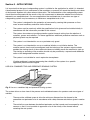
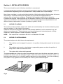
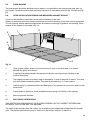
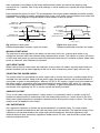
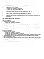
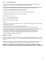
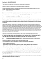
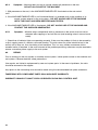
The floor or mounting surface for the sensor mats must be flat, smooth and rigid, i.e. show no perceptible
distortion under the heaviest load anticipated. Undulations, protrusions, large gaps or other irregularities
will increase the sensitivity of the sensor mats and may result in intermittent
unintended switching off (nuisance tripping).
SENSOR
MAT
Ensure that covers and gratings
are flush with floor surface.
No loose debris or protrusions.
SENSOR
MAT
Sensor mat must not
sag or undulate.
No sharp edges.
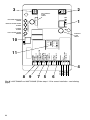
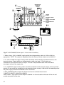
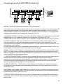
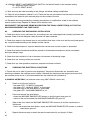
Fig 10 Floor condition for mats.
Small and regular protrusions such as chequer plate pattern are acceptable. Skimmed concrete floors
are ideal. If any doubt exists please contact the supplier.
5.3.7
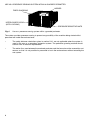
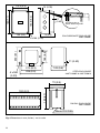
CONTROL UNIT MOUNTING (refer to section 4 fig. 8)
The control unit MUST NOT be mounted within the detection zone.
If access to the control unit is required for manual reset or routine indicator observation, it should be
mounted at an accessible position outside the protection zone which provides a good view of the
hazard and protection zone.
The reset actuator shall be situated outside the protection zone and in a position giving good visability of
the hazard and protection zone.
In other cases, the control unit may be mounted anywhere convenient outside the protection zone taking
into account the access requirements for test and maintenance.
The 440F-C4000D control unit should be mounted within an enclosure to a minimum of IP 54 (in
accordance with EN 60529).
NOTE:
the Control unit is not suitable for direct exposure to high pressure cleaning.
5.4
MAT POSITIONING
5.4.1
FOR USE AS A COMBINED TRIP AND PRESENCE SENSING DEVICE
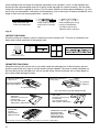
The positioning of the mat edges is calculated as a horizontal distance from the hazard zone. Define the
hazard zone as a volume, taking into account all the possible modes of the machine and all
variations in size of the workpiece. It is essential to record the dimensions and position of the hazard
zone and the assumptions used, so that the adequacy of the safeguarding can be checked.
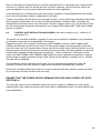
If other safeguarding measures are used in conjunction with the mat system they may affect the
16