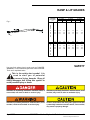
1
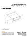
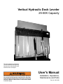
Vertical Hydraulic Dock Leveler
25-50K Capacity
This manual applies to vertical Dock
Levelers manufactured beginning
November 24, 2003 with the serial
numbers 63251 and higher.
User's Manual
Do not install, operate or service this product unless you
have read and understand the Safety Practices, Warnings,
and Installation and Operating Instructions contained in
this User’s Manual. Failure to do so could result in death
or serious injury.
Installation, Operations,
Maintenance and Parts
Part No. 6001762B
LIMITED WARRANTY
4Front Engineered Solutions warrants to and for the sole benefit of the original purchaser of dock levelers and vehicle
restraints manufactured by 4Front Engineered Solutions (the “Products”) that the Products shall be free from defects in
material and workmanship, subject to the following expressed provisions:
Base Limited Warranty - All Products are warranted for one year base period (“Base Warranty Period”) commencing on
the earlier of the date of 4Front Engineered Solutions approved installation or the sixtieth (60th) day after the date of
shipment. This limited warranty covers the repair or replacement of the defective Product units or components at 4Front
Engineered Solutions' sole election and expense, including reasonable labor, travel and freight. If the Product is sold to
the original purchaser through a 4Front Engineered Solutions dealer or distributor, applicable charges for labor, travel
and freight shall not exceed those set forth in 4Front Engineered Solutions’s dealer reimbursement policy.
Hydraulic Limited Warranty - All cylinders and hydraulic power units of the Products described by 4Front Engineered
Solutions as VSL products are warranted to cover the cost of replacement parts only of an extended period of four (4)
years after the Base Warranty Period.
Parts & Assembly Limited Warranty - All spare or replacement parts are warranted to cover the cost of replacement
parts and freight only for (90) days from the date of shipment.
THE ABOVE LIMITED WARRANTIES ARE IN LIEU OF ANY OTHER WARRANTIES, EITHER EXPRESS OR
IMPLIED, INCLUDING BUT NOT LIMITED TO ANY IMPLIED WARRANTY OR MERCHANTABILITY OR FITNESS
FOR A PARTICULAR PURPOSE.
In no event shall 4Front Engineered Solutions or any of its subsidiaries be responsible for or liable to anyone, including
any third parties, for special, indirect, collateral, punitive, incidental or consequential damages. Such excluded damages
include, but are not limited to, loss of goodwill, loss of profits, loss of use, interruption of business, or other similar
indirect financial loss.
This limited Warranty shall be void and of no effect (i) if a Product is altered or modified from its original condition as
installed or as delivered at or from the factory, (ii) to the extent that the Product defect is the direct result of improper
installation, operation beyond capacity or other than in accordance with 4Front Engineered Solutions instructions abuse,
careless or negligent use, or failure to maintain the Product as recommended by 4Front Engineered Solutions or, (iii)
if the original purchaser does not notify 4Front Engineered Solutions’s Warranty Department of the defect within (90)
days after the Product defect is discovered.
©2007 4Front Engineered Solutions, Inc.
6001762B — Vertical Hydraulic Dock Leveler
April 2007
TABLE OF CONTENTS
Warranty . ................................................. 2
Introduction............................................... 3
Owners Responsibilities............................ 4
Deck & Lip Grades.................................... 5
Safety........................................................ 5
Safety Practices........................................ 6
Installation................................................. 7
Components & Specifications................. 13
Hydraulic System Operation................... 14
Operating Instructions
Introduction ......................................... 15
Normal Operation................................ 16
Storing Leveler.................................... 17
End Loading........................................ 17
Service Tools .......................................... 18
Preventative Maintenance....................... 19
Troubleshooting Guide........................... 21
PLC Diagnostics . ................................... 25
Hydraulic Power Unit Adjustment............ 27
Hydraulic Schematic............................... 29
Hydraulic Valve - Cross Section.............. 29
Electrical Schematics
PLC Diagram 120V.............................. 30
PLC Diagram 208V - 575V ................. 31
120V Single Phase ............................. 32
208V - 230V Single Phase ................. 33
208V-575V Three Phase .................... 34
Main Cylinder Adjustment ...................... 35
Parts List
Dock Leveler........................................ 36
Hydraulic.............................................. 39
Hydraulic Power Unit........................... 41
Control Panel....................................... 43
Distributor Information............................. 46
INTRODUCTION
Welcome and thank you for choosing this dock leveler.
This User’s Manual contains information that you need to safely install, operate and maintain the dock
leveler. It also contains a complete parts list and information about ordering replacement parts. Please
keep and read this User’s Manual before using your new dock leveler.
April 2007
6001762B — Vertical Hydraulic Dock Leveler
©2007 4Front Engineered Solutions, Inc.
OWNER'S RESPONSIBILITIES
The owner's responsibilities include the following:
The owner should recognize the inherent danger of the
interface between dock and transport vehicle. The owner
should, therefore, train and instruct operators in the safe
use of dock leveling devices.
When a transport vehicle is positioned at the dock, there
shall be at least 4" of overlap between the front edge of the
lip of the dock leveler and the edge of the floor or sill of the
transport vehicle.
Nameplates, cautions, instructions and posted warnings shall
not be obscured from the view of operating or maintenance
personnel for whom such warnings are intended.
Manufacturer's recommended periodic maintenance and
inspection procedures in effect at time of shipment shall be
followed, and written records of the performance of these
procedures should be kept.
A dock leveler that is structurally damaged or has experienced
a sudden loss of support while under load, such as might
occur when a transport vehicle is pulled out from under the
dock leveler, shall be removed from service, inspected by
the manufacturer's authorized representative, and repaired
as needed before being placed back in service.
The owner shall see that all nameplates, caution and
instruction markings or labels are in place and legible and
that the appropriate operating and maintenance manuals
are provided to users.
Modifications or alterations of dock leveling devices
shall be made only with written permission of the original
manufacturer.
When industrial trucks are driven on and off transport vehicles
during the loading and unloading operation, the brakes on
the transport vehicle shall be applied and wheel chocks
or positive restraints that provide the equivalent of wheel
chocks engaged.
The dock leveler should never be used outside its vertical
working range or outside the manufacturer's labeled rated
capacity. It must also be compatible with the loading
equipment and other conditions relating to the dock.
©2007 4Front Engineered Solutions, Inc.
6001762B — Vertical Hydraulic Dock Leveler
April 2007
RAMP & LIP GRADES
TRUCK BED
POSITION
from DOCK,
(in.)
Fig. 1
A
B
O
V
E
D
O
C
K
B
E
L
O
W
DECK and LIP grades, % for Dock leveler length
5’ Leveler
6’ Leveler
8’ Leveler
DECK
LIP
DECK
LIP
DECK
LIP
6.0
4.0
2.0
11.4
8.4
5.4
5.2
2.2
-0.8
9.7
7.2
4.6
3.4
0.9
-1.7
7.4
5.5
3.5
1.2
-0.8
-2.7
0.0
2.4
-3.8
2.1
-4.2
1.6
-4.7
-2.0
-4.0
-6.0
-0.6
-3.6
-6.6
-6.8
-9.8
-12.8 -0.5
-3.0
-5.6
-6.7
-9.3
-11.8 -0.4
-2.3
-4.3
-6.6
-8.6
-10.5
D
O
C
K
Deck and lip grade, 16” lip.
You may find safety signal words such as DANGER,
WARNING, or CAUTION throughout this Owner’s Manual.
Their use is explained below.
SAFETY
This is the safety alert symbol. It is
used to alert you to potential
personal injury hazards. Obey all
safety messages that follow this symbol to
avoid possible injury or death.
Indicates an imminently hazardous situation which, if
not avoided, will result in death or serious injury.
Indicates a potentially hazardous situation which, if not
avoided, may result in minor or moderate injury.
Indicates a potentially hazardous situation which, if not
avoided, could result in death or serious injury.
Caution used without the safety alert symbol indicates
a potentially hazardous situation which, if not avoided,
may result in property damage.
April 2007
6001762B — Vertical Hydraulic Dock Leveler
©2007 4Front Engineered Solutions, Inc.
SAFETY PRACTICES
Read these safety practices before installing, operating
or servicing the dock leveler. Failure to follow the safety
practices could result in death or serious injury.
If you do not understand the instructions, ask your supervisor
to explain them to you or call 4Front Engineered Solutions at
(972) 466-0707 (USA) or (519) 457-7155 (CAN.).
DO NOT walk in front of dock leveler until you:
- Restore the leveler to its safe stored vertical position with
lip extended.
- Press Emergency Stop button to stop the leveler and lip
from moving.
Move all equipment, material or people off the dock leveler
and store the dock leveler after use.
Do not use a fork truck or other material handling equipment
to lower the leveler.
OPERATION:
Restrict use of dock leveler to trained operators. Follow safe
operating procedures described in this manual and in the
operation placard which was shipped with the leveler. The
placard should be posted near the leveler. If either labels or
placard is lost, call 1-800-525-2010 or 972-466-0707 for a free
replacement.
Many trailers have air ride suspension that may cause the trailer
to move away from the dock during loading and unloading
operations (commonly referred to as trailer walk). The potential
for trailer walk caused by air ride suspension may be reduced
by exhausting or "dumping" the air from the suspension system
before servicing the trailer.
Do not use the dock leveler to service trailers outside of its
intended working range which is 6" above dock and 6" below
the building floor.
INSTALLATION, MAINTENANCE AND SERVICE:
Place barricades on the dock floor around the dock leveler
and in the driveway in front of the dock leveler while installing,
maintaining or repairing the dock.
Do not operate the dock leveler when anyone is in front of it.
Do not operate the dock leveler with equipment, material or
people on the ramp or lip.
Stay clear of the dock leveler when it is moving.
KEEP HANDS CLEAR OF HINGES AT ALL TIMES. Do not
use hands to position dock leveler ramp or lip, or to store
dock leveler.
Do not use the dock leveler if it appears damaged or does not
operate properly. Inform your supervisor immediately.
Do not attempt to manually lift the dock leveler ramp or lip. If the
dock leveler does not operate correctly using the operational
procedures contained in this manual, do not use the leveler.
Refer to the troubleshooting guide in this manual. If Leveler
still does not operate properly call an authorized service
representative.
Do not stand in the driveway between the dock leveler and
the backing truck.
Chock truck wheels or lock truck into place with truck restraining
device and set brakes before loading or unloading.
Never drive on dock leveler unless Green Light is lit on the dock
leveler control panel and the truck bed supports extended lip
or ramp is supported by the concrete below.
Always restore leveler to its safe stored vertical position with lip
extended and Emergency Stop button pressed after servicing
truck.
©2007 4Front Engineered Solutions, Inc.
If the leveler is left in a disabled condition, the lock-out pin must
be padlocked in position.
Do not operate the dock leveler when anyone is standing in
front of the dock leveler.
Before doing any maintenance or repair under the leveler be
certain that the leveler is stored with the lock-out pin inserted
through the maintenance post and bracket on the deck, the
Emergency Stop button is pressed, the power is disconnected
and properly tagged or locked out, and barriers are in place.
Disconnect the power and properly tag or lock out before
entering the pit or doing any maintenance or repair under the
leveler.
All electrical troubleshooting or repair must be done by qualified
technician and must meet applicable codes.
If it is necessary to make troubleshooting checks inside the
control box with power on, USE EXTREME CAUTION! Do
not place fingers or uninsulated tools inside the control box.
Touching wires or other parts inside the control box could result
in electrical shock, serious injury or death.
Vertical levelers ship partially disassembled and require field
assembly. Prior to complete electrical and hydraulic installation,
levelers should be stored safely. If leveler is mounted on hinges
and stored vertically, the lock-out pin must be inserted through
the maintenance post and the bracket on deck, and secured
with a padlock until the leveler is completely wired, tested, and
fully operational.
6001762B — Vertical Hydraulic Dock Leveler
April 2007
INSTALLATION
INSTALLATION OF DOCK LEVELER
Important Installer Responsibility
Vertical levelers ship partially disassembled and require
field assembly. Prior to complete electrical and hydraulic
installation, levelers must be stored safely. If leveler is
mounted on hinges and stored vertically, maintenance
post must be secured with lock-out pin and padlock
until the leveler is completely wired, tested and fully
operational. Padlock must not be removed until leveler
is completely wired, tested, and fully operational.
Failure to follow safety practices could result in death
or serious injury.
Make sure lifting devices are in good condition and have
a rated capacity of at least 3000 lb. at the lifting angle
they are being used. Stand clear of the dock leveler
when it is being placed into the pit. Never allow anyone
to stand on or near the dock leveler when it is being
lifted or placed into the pit. The dock leveler can tip or
swing into bystanders which could result in death or
serious injury.
Fig. 2
3/4" UNC load
centering eyebolt
GENERAL INFORMATION
The successful installation of a vertical leveler requires good
coordination with other trades involved on the site. You
must have a clear access to the dock area, inside and out.
Ideally, the leveler should not be installed until the control
panel is installed, has live power connected to the control
panel, and field wiring to the power unit is complete. This
will allow the complete installation at one time as opposed
to making several trips. The bumper assemblies must not
be installed until the leveler is functional as pit construction
errors may not be evident until that time.
The installed location of the control panel and hydraulic
power unit must be specified on a job specific "Approval
Drawing". Check with the general contractor or sales person
for this information.
PIT CHECK
Check the entire dock leveler pit for proper construction
according to the job specific approval drawings. Check
electrical service running to the control panel to ensure it
agrees with the phase and voltage of the motor and control
box supplied with the dock leveler. See the wiring diagram
located inside the control panel. Schematics for standard
control panels are provided in this manual.
Take care when moving the dock leveler to ensure that the
electrical and hydraulic components are not damaged.
April 2007
6001762B — Vertical Hydraulic Dock Leveler
©2007 4Front Engineered Solutions, Inc.
INSTALLATION, continued
HANDLING AND UNLOADING
The rear fixed hinge channels will be installed first by the
concrete contractor. In most cases, these components will
have arrived at the site much earlier than the levelers. The
levelers will arrive on a truck laid flat with the hydraulic
cylinders facing upward. Spacers will be inserted between
the levelers to prevent damage to the leveler components.
The levelers can be lifted off the truck in stacks of three but
using the forks to separate the levelers is not recommended
as damage to the hydraulic components may occur. The
levelers should be lifted individually by installing a 3/4" UNC
load centering eyebolt through the hole supplied in the lip
plate. See Fig.2.
Fig. 3
TO INSTALL
1. Mount and wire the control panel in the location as shown
on the job specific approval drawing. Ensure that the
voltage and phase of the incoming power agrees with
the control panel and the decals on the pump and motor.
Power to the control must come from a user supplied
fused disconnect with correct fuse sizes for the voltage
and phase of the motor. See electrical diagram for correct
fuse size.
2. Pick up the leveler using the load centering eyebolt, and
suspend the leveler vertically as shown in Fig. 2.
3. Align the leveler rear hinges with the fixed hinge section
and insert the two outer hinge pins from the side without
standing in front of or underneath the suspended
leveler. Do not install the center pin until the maintenance
post has been installed and secured.
Fig. 3 shows placement of the pins.
4. Insert the maintenance post bar through the guide bracket
on the leveler and secure the lower end to the frame with
the pin. Note: Strut is not symmetric. Larger hole in
strut pins to deck. Insert the pin from the side without
standing in front of or underneath the suspended
leveler. See Fig. 3.
5. Allow the leveler to lean away from the dock door until the
lock-out pin can be inserted through the upper end of the
maintenance post and the bracket on the deck. See Fig.
12, page 18. Place a padlock through the hole provided
in the lock-out pin. This will prevent any unauthorized
activation of the leveler and is essential to the personal
safety of anyone near this leveler.
©2007 4Front Engineered Solutions, Inc.
Ensure that the leveler is leaning away from the dock
door. If the leveler is standing vertical or leaning towards
the dock door do not proceed with installation.
The lock-out pin must be inserted through the
maintenance post and the bracket on the deck. The pin
must be secured with a padlock before the lifting device
is removed. Failure to do so could result in death or
serious injury.
See Fig. 12 on page 18 for lock-out pin location.
6001762B — Vertical Hydraulic Dock Leveler
April 2007
6. Install the center hinge pin. Do not force pins through with
a hammer as this may damage ring grooves. Secure
all three leveler hinge pins and the lower pin of the
maintenance post with the retaining clips provided. See
Fig.3 for reference.
INSTALLATION, continued
7. Remove the lifting device from the leveler lip. Leave the
lip fully extended.
8. The hydraulic power unit is pre-assembled on a mounting
bracket with all valves attached. This mounting bracket
is designed to suit many different applications. The
mounting position is specified on the job specific approval
drawing for the project. Fasten the power unit mounting
bracket as required.
9. Lay cardboard or other absorbent material under the
hydraulic power unit. This prevents staining the floor in
the event of an overflow. Place a pan directly under the
reservoir to catch any spilled fluid.
10. The electrician can now connect the wiring from the
control panel to the motor and solenoid valves.
11. Mark the 3 hydraulic hoses and the leveler stored and
maintained float sensor cables (located on the deck) with
colored tape or numbers for identification. Do not remove
the plugs from the hydraulic hoses at this time. Feed
the hose assemblies and the sensor cables through the
conduit (if equipped).
12. Remove the plugs and make the connections to the
correct hose fittings. Refer to Fig. 14 on page 27 and page
37 for the hydraulic hoses connections. These fittings are
all JIC type and require no thread sealant. If the hoses are
too long, coil the hoses neatly at the bottom of the power
unit and secure with plastic ties. Do not leave excess hose
under the leveler but leave a loop so hoses are not pulled
tight, see Fig. 25 on page 36. Connect the leveler stored
and maintain float sensor cables to the control panel.
Do not remove the lock-out pin from the maintenance
post until the following steps have been completed to
ensure that the leveler is functioning property. Failure
to do so could result in death or serious injury.
April 2007
6001762B — Vertical Hydraulic Dock Leveler
©2007 4Front Engineered Solutions, Inc.
INSTALLATION, continued
13. Remove shipping plug from the hydraulic reservoir and
replace with the breather cap.
14. Pull out the Emergency Stop button. The amber power
light should be on. Press and hold the Raise push
button for only 5 seconds while looking into the hydraulic
reservoir fill hole. If the motor is turning in the correct
direction you will immediately see the fluid level drop.
If after 5 seconds you see no drop in fluid level, stop
the pump and switch wires to reverse the rotation. See
troubleshooting guide and electrical schematics in this
manual to correct.
15. Press and hold the Raise push button. The main cylinder
will begin to extend in an abrupt motion. Hold the cylinder
away from the leveler while extending so that it will
extend freely. (The cylinder rod or adjusting end may be
damaged by contact with the deck while extending)
16. If the sound of the pump changes before the cylinder
reaches its full stroke (16") , stop the pump and add 8
ounces of hydraulic fluid (see page 14 under Components
& Specifications for hydraulic fluid specifications).
Continue to run the pump until the main cylinder is fully
extended. Add more fluid if required.
17. Press the Lower button and hold until the main cylinder
is fully retracted. This will eliminate excess air from the
main cylinder. Then press the Lip Retract button and
hold until the lip is fully retracted. Then press the Lip
Extend button and hold until the lip is fully extended.
Then press the Lip Retract button again and hold until
the lip is fully retracted. This will eliminate air from the
lip cylinder. Run both cylinders in/out a minimum of 4
times until any abrupt motion is eliminated.
18. With both the main cylinder and the lip cylinder retracted,
check the oil level in the reservoir. Oil should be clear
and within 1/2" of the top with the lip plate fully retracted.
Add oil if necessary. See page 14 under Components &
Specifications for hydraulic fluid specifications. If the oil
is foamy, leave for approximately 15 minutes to let the
oil settle before checking oil level.
19. This step requires 1-1/2" and 2" open end wrenches.
Loosen the jam nut on the threaded rod end of the main
cylinder. Press the Raise button and hold until the main
cylinder is fully extended. With the main cylinder rod
fully extended, rotate the rod end so that the pivot pin
can be inserted freely through the cylinder pivot on the
embedded channel frame. Secure the pivot pin with the
clips provided. See page 35. Ensure the grease fitting
10 ©2007 4Front Engineered Solutions, Inc.
6001762B — Vertical Hydraulic Dock Leveler
April 2007
INSTALLATION, continued
Incorrect hydraulic power unit adjustment that allows
the leveler to descend rapidly could result in death or
serious injury.
Fig. 4 – Typical Bumper Installation using VB420-11F
bumpers
20. Using the 2" wrench to hold the chrome cylinder rod,
tighten the jam nut using the 1-1/2" wrench. Turn the
chrome cylinder rod clockwise to pull the leveler forward
until the pins in the maintenance post move freely.
There must not be more than 1-1/2 inches of thread
showing on the adjustable rod end below the jam
nut. If more than 1-1/2 inches of thread shows, do not
proceed.
21. Ensure that the pit area is clear. Remove the padlock
from the lock-out pin. Stand at the side of the leveler,
reach in and remove the lock-out pin from the
maintenance post.
22. Press and hold the Lower button. The pump will run and
the leveler will move forward and start to lower. The alarm
will sound if the leveler is stopped between the lowered
working range and the stored position. Continue to press
the Lower button until the pump stops. The leveler will
hesitate momentarily when it reaches the working range,
then continue to float down. The Green light on the control
panel should be on. Visually check that the ramp stops
are resting on the front curb steel. Press the Lip Retract
button on the control panel until the lip is pendant.
23. Press and hold the Raise button until the leveler is
raised above the working range and the Green light goes
off. Release the pushbutton. The leveler should remain
in position and the alarm should sound. Release the
pushbutton. The leveler should remain in position and
the alarm should sound.
24. Press and hold the Raise button until the leveler reaches
the stored position and the lip is fully extended. The Green
light on the control panel should remain off and the alarm
should not sound. Insert the lock-out pin through the
maintenance post and bracket on the deck. The pin must
insert freely. If there is any resistance, adjust the hydraulic
cylinder as described in steps 17 & 18 on page 10.
April 2007
6001762B — Vertical Hydraulic Dock Leveler
©2007 4Front Engineered Solutions, Inc.
11
Command=ToggleDesktop
INSTALLATION, continued
25. Remove the lock-out pin and lower the leveler as
instructed in step 21. Observe the lowering speed of the
leveler after it reaches the working range. The leveler
lowering speed should match the leveler power down
portion of the lowering. Adjust shuttle valve as necessary,
see page 28.
26. With the leveler in the fully lowered position, place each
bumper assembly on the floor between the leveler and
the door jamb. A 1" space must be present between the
side of the leveler and the nearest face of the bumper
assembly. This space is important for the bottom seal to
work properly. The bumper assemblies must be welded
to the front curb steel using proper weld techniques.
Vertical down weld passes are not acceptable. All
applicable anchors must be 3/4" x 6" (min. depth). Refer
to Fig. 4.
27. Permanently mount the laminated WARNING and
OPERATION instruction placard near the dock leveler
control panel.
12 ©2007 4Front Engineered Solutions, Inc.
6001762B — Vertical Hydraulic Dock Leveler
April 2007
COMPONENTS & SPECIFICATIONS
The main components of the leveler are shown below. See the Parts List for specific part numbers.
Fig. 5
Velocity Fuse
Lip Plate
Lip Cylinder
User Warning
Label
(on both sides)
Lip Hinge
Warning
Labels
Deck
Assembly
Lock-Out Pin
with Warning
Tag
Maintenance
Post
Main Lift Cylinder
Adjustable Rod End
Control Panel
GREEN LIGHT
Push and hold to raise
dock leveler.
Raise
Lip plate will extend when
leveler is fully raised.
When fully raised push
the Emergency Stop.
Lip Extend
Push to extend lip plate.
Release at desired lip
extension.
Lip Retract
Push to retract lip plate.
Release at desired lip
retraction.
Raise (Blue Push-button)
Lip Extend (Green Push-button)
Lip Retract (Black Push-button)
Lower (Yellow Push-button)
Emergency Stop (Red Push/Pull Mushroom Style Push-button)
Lower
Release Emergency Stop.
Push and hold Lower button
until green light indicates
leveler has reached operating
range.
Power On
Do not use leveler
if light is flashing.
AMBER LIGHT
ART-162A
April 2007
6001762B — Vertical Hydraulic Dock Leveler
©2007 4Front Engineered Solutions, Inc.
13
COMPONENTS & SPECIFICATIONS, continued
Control Panel (Standard) - NEMA 12, automatic motor
starter, thermal overload, resettable control circuit
breaker. U.L. approved.
Pilot Light - LED.
Solenoid Valves - 24VAC.
Motor - NEMA Standard T.E.N.V. / 56C frame,
1 h.p. @ 15 mi. duty cycle, single or three phase.
Pump - Fixed displacement gear pump, 1 gpm, primary
relief valve factory set at 2000 psi.
Reservoir Capacity - 1 U.S. gal., (3.8 lit.) level measured
by dipstick.
Hydraulic Fluid - Acceptable Hydraulic fluids:
Shell Tellus T 15
Mobil Aero HFA (49011)
Exxon Univis Grade J13
Texaco Aircraft Oil #1554
U.S. Oil Co., Inc #ZFI-5606 (Low Temp.)
HYDRAULIC SYSTEM OPERATION
The following describes the operation of the hydraulic and electrical system when the controls are
AUDIBLE ALARM
• Sounds when leveler stops between working range
and fully stored position.
• Will silence when Raise, Lower or EMERGENCY
STOP is pressed.
EMERGENCY STOP
Push in
• Power cut off to motor circuit.
• Amber pilot light turns off.
• Solenoid valves SV2 and SV3 deenergized
preventive leveler movement.
Pull out
• Power connected to motor circuit.
• Amber pilot light turns on.
• Main solenoid valves SV2 and SV3 remains closed
except when pump is running or leveler is lowered
to working range.
LOWER
• Pump starts and shuttle valve shifts.
• Lower solenoid valve SV1opens to retract main
cylinder. When leveler lowers to working range,
the pump stops, the Lower solenoid valve SV1
closes and Main solenoid valves SV2 and SV3
open to allow leveler to float down to the truck
bed.
• Lip solenoid valve SV4 closes to prevent lip from
retracting.
• Green pilot light turns on when leveler reaches
working range
14 ©2007 4Front Engineered Solutions, Inc.
RAISE
• Pump starts and shuttle valve shifts.
• Main solenoid valves SV2 & SV3 open to extend
main cylinder.
• Lip solenoid valve SV4 closes to prevent lip from
retracting.
• Green pilot light turns off when leveler raises
above working range.
Fully Raised
• Leveler stored sensor closes.
• Pressure increases
• Sequence valve shifts
• Lip cylinder extends.
LIP RETRACT
• Pump starts and shuttle valve shifts.
• Main solenoid valves SV2 & SV3 open allowing
leveler to raise and lip to retract.
• Green pilot light turns off when leveler raises
above the working range.
LIP EXTEND
• Pump starts and shuttle valve shifts.
• Main cylinder solenoid valve is closed.
• Lip solenoid valve opens allowing lip to extend.
6001762B — Vertical Hydraulic Dock Leveler
April 2007
OPERATING INSTRUCTIONS
INTRODUCTION
Before operating the dock leveler, read and follow the
Safety practices on page 6.
Restrict use of dock leveler to trained operators. Follow
safe operating procedures described in this manual and
in the operation placard which was shipped with the
leveler. The placard should be posted near the leveler.
If either labels or placard is lost, call 1-800-525-2010 or
972-466-0707 for a free replacement.
DO NOT USE DOCK LEVELER IF IT LOOKS DAMAGED,
OR DOES NOT SEEM TO WORK PROPERLY. Inform your
supervisor immediately.
Always be certain that the truck wheels are chocked, or
that the truck is locked in place by a truck restraining
device and the brakes are set before loading or
unloading. Trucks pulling away unexpectedly can cause
uncontrolled drop of the dock leveler which can result
in death or serious injury.
The 4Front Engineered Solutions vertical dock leveler is
designed to span and compensate for space and height
differences between a loading dock and freight carrier to
allow safe, efficient freight transfers.
The 4Front Engineered Solutions vertical dock leveler uses
push button controls to position the ramp. Pressing and
holding the Lower button operates a hydraulic pump and
retracts a hydraulic cylinder to lower the ramp. When the ramp
is lowered to the working range, it floats down to rest on the
bed of a trailer forming a bridge. After loading, pressing and
holding the Raise button extends the hydraulic cylinder to
raise the ramp to the stored position. When the dock leveler
reaches its full raised position, a second hydraulic cylinder
extends the dock leveler lip.
Push the Emergency Stop when the leveler is stored to
prevent operation. With the dock leveler in its fully stored
position, a maintenance post may be secured with a lock-out
pin to prevent inadvertent operation.
Never drive on dock leveler unless Green Light is lit on
the dock leveler control panel and truck bed supports the
extended lip or the ramp is supported by the concrete
below.
Always return the dock leveler to its safe stored vertical
position with lip extended with the Emergency Stop
button pressed after servicing truck.
If the truck pulls away before the dock leveler is stored,
the lip will fall to its pendant position and will not be
supported. In addition, failure to properly store the dock
leveler may leave the leveler in a position below dock
level. These conditions may result in unexpected drop
of personnel or material handling equipment and result
in death or serious injury.
DO NOT walk in front of dock leveler until you:
• Restore the leveler to its safe stored vertical
position with lip extended.
• Press Emergency Stop button to stop the leveler
from moving.
April 2007
6001762B — Vertical Hydraulic Dock Leveler
©2007 4Front Engineered Solutions, Inc.
15
OPERATING INSTRUCTIONS
Safety First:
1. Always secure the truck with a vehicle restraint or
wheel chocks and set brakes before operating the
dock leveler.
2. Do not operate dock leveler with anyone standing on
or in front of it.
3. Always keep hands and feet clear of all moving
parts.
4. Always restore the leveler to its safe stored vertical
position with the lip extended and the Emergency
Stop button pressed after servicing truck.
5. Press EMERGENCY STOP button to stop leveler &
lip from moving.
6. DO NOT walk in front of dock leveler until you:
- Restore the leveler to its safe stored vertical position
with lip extended.
- Press the Emergency Stop button to stop the leveler
from moving.
Failure to do so could result in death or serious injury.
CONTROLS
Green light on
Press lower button
Pull for power on
Amber light on
Powered/
Float down
Fig. 7
Normal Operation
1. To lower the dock leveler pull the EMERGENCY
STOP button on control panel to switch on power.
Amber light indicates power on. Press and hold
LOWER button. The pump will start and the
leveler will start to lower. Release the LOWER
button when the Green light on the control panel
turns on. (Green light on leveler control panel
indicates leveler has reached operating range)
The leveler will float down to the truck bed. See
Fig. 7.
2. To stop the leveler, release the LOWER button.
Audible Alarm will sound if the button is released
before the leveler is in its operating range. Push
the EMERGENCY STOP button at any time to
stop all operation and silence the Audible Alarm.
If this condition persists, a short duration tone will
sound periodically to remind the operator of the
illegal leveler condition. Amber and green lights
will turn off. To resume operation of the leveler,
pull the EMERGENCY STOP button (amber light
on) and press and hold the LOWER button and
leveler will float down to the truck bed. Release
the LOWER button when Green light on leveler
control panel indicates leveler has reached the
operating range. See Fig. 8.
16 ©2007 4Front Engineered Solutions, Inc.
CONTROLS
Green light
Press to lower
Push to stop. Pull for power on
Amber light
Fig. 8
Note: Audible alarm pulses and green lamp goes off if
the EMERGENCY STOP button is pressed while leveler
is in float range. Amber lamp flashes if both LS1 & LS2
are on or an overload condition exists.
6001762B — Vertical Hydraulic Dock Leveler
April 2007
OPERATING INSTRUCTIONS, continued
CONTROLS
Storing Leveler
Green light off
Press raise button
3. To return the leveler to its vertical stored
position, press and hold the RAISE button.
Green light will turn off. Audible Alarm will sound
if the button is released before the leveler is
fully raised. When the leveler is fully raised and
the lip is extended, release the RAISE button.
Push the EMERGENCY STOP button to turn
off power (amber light off). See Fig. 9.
Push for power off
Amber light off
Fig. 9
End Loading Operation
1. Pull the EMERGENCY STOP button to switch
on power. Amber indicates power on. Press and
hold LOWER button until the leveler is partially
lowered. Press and hold LIP RETRACT button
until the lip is fully retracted. Press and hold
LOWER button until Green light on leveler
control panel indicates the leveler has reached
the operating range. Leveler will float down to
the pit floor. See Fig. 10.
CONTROLS
Green light on Lip in
Press to retract lip
Press lower button
Pull for power on
Amber light on
Float down
Fig. 10
CONTROLS
2. To reposition the leveler for normal loading/
unloading, press the RAISE button until lip
is clear of the truck. The Green light will go off
and the Audible Alarm will sound if the leveler is
stopped above the operating range. Press the
LIP EXTEND button until lip is fully extended.
If above the operating range press and hold
the LOWER button until the Green light on the
control panel indicates leveler has reached the
operating range. Leveler will float down to the
truck bed. See Fig. 11.
Green light
Press to raise
Press to extend lip
Press to lower
Lip out
Push to stop.
Pull for power on
Amber light
Raise
Float down
Fig. 11
April 2007
6001762B — Vertical Hydraulic Dock Leveler
©2007 4Front Engineered Solutions, Inc.
17
SERVICE TOOLS
Before servicing the dock leveler, read and
follow the Safety Practices on page 6 and the
Operation section in this manual.
Before doing any maintenance or repair on the dock
leveler, be certain that:
1) THE LEVELER IS STORED IN A VERTICAL POSITION
WITH THE LIP EXTENDED AND THE LOCK-OUT PIN
INSERTED THROUGH THE MAINTENANCE POST AND
BRACKET ON DECK.
2) The Emergency Stop button is pressed.
3) Barriers are in place.
Fig. 12
Failure to do so could result in death or serious injury.
Maintenance Post
Padlock
The vertical dock leveler is equipped with a maintenance
post to hold the leveler in the stored position during
maintenance. Always follow the procedure below when
performing maintenance or adjustments of any kind to the
dock leveler.
Guide Bracket
Lock-Out Pin
Warning Tag
1) Raise the leveler to its fully stored position with the lip
extended.
2) Press the EMERGENCY Stop Button on the control
panel.
3) Insert the Lock-Out Pin through the maintenance post
and the bracket on the deck. (Reach from the side of the
leveler while inserting Lock-Out Pin). The Lock-Out Pin
should insert freely.
Maintenance Post
4) Place a padlock through the hole in the Lock-Out Pin to
prevent accidental activation of the dock leveler.
5) Place barricades around the dock leveler to show leveler
is out of service.
18 ©2007 4Front Engineered Solutions, Inc.
6001762B — Vertical Hydraulic Dock Leveler
April 2007
PREVENTATIVE MAINTENANCE
To ensure the continued good operation of your dock leveler, perform the following preventative
maintenance procedures.
Before servicing the dock leveler, read and
follow the Safety Practices on page 6 and the
Operation section in this manual.
Before doing any maintenance or repair on the dock
leveler, be certain that:
1) THE LEVELER IS STORED IN A VERTICAL POSITION
WITH THE LIP EXTENDED AND THE LOCK-OUT PIN
INSERTED THROUGH THE MAINTENANCE POST AND
BRACKET ON DECK.
2) The Emergency Stop button is pressed.
3) The power is disconnected and properly tagged or
locked out.
4) Barriers are in place.
Failure to do so could result in death or serious injury.
Weekly
Quarterly
1. Check that the lock out pin can be freely
inserted through the maintenance post and
the bracket on the deck when the leveler is
fully raised.
2. Check the full operation of the leveler to
ensure there is no hesitation in the hydraulic
system. Any loss of fluid will affect the safety
valve operation.
3. Inspect that both control panel lights are
working and replace bulbs if necessary.
4. Clean away any debris from the pit area. If
washing out, take care not to direct spray at
any electrical parts.
5. Clean away any dirt and debris from the lip
hinge.
April 2007
1. Inspect and lubricate all mechanical pivot
points on the leveler with S.A.E. 30 oil. Cycle
the leveler when lubricating.
2. Inspect the hydraulic cylinders, valves and
hoses for any fluid loss and check the reservoir
level with the leveler fully lowered with the lip
pendant. Add fluid as required (fluid level
should be 1/2" from top of reservoir).
3. Inspect all welds under leveler for fatigue or
failure, particularly the lip plate hinge and
under the top plate.
4. Inspect all warning labels and placard.
Replace as required. See page 20 for part
numbers and label location.
6001762B — Vertical Hydraulic Dock Leveler
©2007 4Front Engineered Solutions, Inc.
19
PREVENTATIVE MAINTENANCE, continued
WARNING LABELS AND OPERATION PLACARD LOCATION
Call 1-800-525-2010 or 972-466-0707 for free replacements.
Fig. 13
6000847
6000848
6000873
6000849
Do not remove the lock-out pin from the maintenance
post unless authorized personal have confirmed that the
hydraulic cylinders, valve and hoses have been properly
installed and filled with fluid.
Failure to do so could result in death or serious injury.
6000873A
6004101
OPERATIONS
WARNING AND OPERATION PLACARD
(MOUNTED NEAR CONTROLS)
20 ©2007 4Front Engineered Solutions, Inc.
6001762B — Vertical Hydraulic Dock Leveler
April 2007
TROUBLESHOOTING GUIDE
Use the Troubleshooting Guide if ever the leveler fails to perform properly. Find the condition that most
closely matches your situation and make the recommended adjustments. Observe all safety warnings
before attempting any maintenance procedure.
Before servicing the dock leveler, read and follow the
Safety Practices on page 6 and the Operation section
in this manual.
Be certain before doing any maintenance or repair on
the dock leveler, that: 1) THE LEVELER IS STORED
IN A VERTICAL POSITION WITH THE LIP EXTENDED
AND THE LOCK-OUT PIN INSERTED THROUGH THE
MAINTENANCE POST AND BRACKET ON DECK and
2) The power is disconnected and properly tagged or
locked out.
Do not enter the area in front of, or under the leveler
unless the leveler is fully raised and lip extended, lockout pin is inserted through the maintenance post and
bracket on deck, the Emergency Stop button is pressed,
and barriers are in place.
Do not disconnect hoses unless the leveler is fully raised
with lip extended, the lockout pin is inserted through the
maintenance post, Emergency Stop button is pressed,
and barriers are in place. After replacing hoses and/or
motor/pump, cycle the leveler at least 4 times to remove
air from the cylinder. Check oil and add if required.
Failure to do so could result in death or serious injury.
If the dock leveler will not raise and it must be raised
by external mechanical means to close the dock door,
use extreme caution and do not allow anyone to stand
in front of the leveler. Ensure that the lock-out pin is
inserted through the maintenance post and bracket on
deck before the mechanical lifting means is removed.
If the dock leveler has been raised to the stored position
by external means, or if the motor/pump unit or any
hydraulic component, or cylinder has been replaced, the
lock-out pin must not be removed from the maintenance
post until the hydraulic system has been bled of air
and all hydraulic functions have been tested. Remove
the pin from the main cylinder rod end and perform
steps 17 through 24 of the Installation Instructions on
pages 10 and 11. If the dock leveler has been raised
to the stored position by external means, there may
be a vacuum exerting a strong retracting force on the
cylinder rod. Loosen the hydraulic hose fitting on the
top port of the main cylinder and allow air to fill the
vacuum before attempting to remove the pin from the
cylinder rod end.
Failure to do so could result in death or serious injury.
April 2007
6001762B — Vertical Hydraulic Dock Leveler
©2007 4Front Engineered Solutions, Inc.
21
TROUBLESHOOTING GUIDE, continued
Do not disconnect hoses or any hydraulic components
unless the leveler is fully raised with lip extended, the
lockout pin is inserted through the maintenance post,
Emergency Stop button is pressed, and barriers are in
place.
If you do disconnect any hydraulic components remove
the pin from the main cylinder rod end and perform
steps 17 through 24 of the Installation Instructions on
pages 10 and 11 before removing the lockout pin from
the maintenance post and bracket on deck.
Failure to do so could result in death or serious injury.
Problem
Possible Cause
1. Leveler does not raise or lower. Motor a) No electrical power to control panel.
not running.
b) Check that wiring matches the wiring
diagram.
c) No electrical power to PLC.
c) No electrical wiring to the PLC.
d) PLC not running.
d) If the fault light is flashing, replace
PLC.
©2007 4Front Engineered Solutions, Inc.
a) Check all wiring connections from line
to motor starter relay, overload and to
motor.
b) Voltage drop due to long wiring distance
from power source.
b) Check voltage when motor is started.
Voltage drop is more often a problem on
single phase motors. Verify wire gage is
adequate for length of wire.
a) Overload relay set too low.
a) Set overload to full load current specified
for voltage on motor nameplate.
b) Loss of 1 phase (Three phase only)
b) Check for voltage at all three motor
connections (T1, T2, T3) at output of
overload in control panel.
4. Leveler does not raise or lower. Motor a) Voltage drop.
hums.
b) Loss of 1 phase (Three phase only)
22 a) Check that voltage is present at terminal
connections to the control panel.
b) Electrical connections incorrect or
broken.
2. Leveler does not raise or lower; motor a) Loose wiring connection.
starts then stops, motor starter relay
chatters.
3. Overload relay tripping (check full
load amperage and relay setting).
Solution
a) See solution 2. b).
b) Check for voltage at all three motor
connections (T1, T2, T3) at output of
overload in control panel.
6001762B — Vertical Hydraulic Dock Leveler
April 2007
TROUBLESHOOTING GUIDE, continued
Do not disconnect hoses or any hydraulic components
unless the leveler is fully raised with lip extended, the
lockout pin is inserted through the maintenance post,
Emergency Stop button is pressed, and barriers are in
place.
If you do disconnect any hydraulic components remove
the pin from the main cylinder rod end and perform
steps 17 through 24 of the Installation Instructions on
pages 10 and 11 before removing the lockout pin from
the maintenance post and bracket on deck.
Failure to do so could result in death or serious injury.
Problem
Possible Cause
5. Leveler does not raise or lower. Motor
runs.
6. Leveler will not lower. Motor runs and
leveler raises.
April 2007
Solution
a) Low fluid in reservoir.
a) Check fluid level with leveler fully
lowered. Oil level should be 1/2-3/4"
bwlow top of reservoir with lip pendant.
Add oil if required..
b) Main solenoid valves SV2 & SV3 do
not open.
b) Check for magnetism at solenoid coil.
If magnetism present, remove and
inspect valve for contamination and
then replace solenoid valve.
c) Pump running in reverse (three phase
only).
c) Check motor rotation & reverse electrical
connections T1 & T2 if necessary.
d) Pump damaged or broken internally.
d) With the leveler safely secured by the
lock-out pin inserted in the maintenance
post and bracket on deck, remove the
hose from the upper port of the main
lift cylinder and point free end into the
reservoir opening. If no fluid is pumped,
replace hydraulic power unit.
e) Insufficient pressure. Primary relief
valve setting too low.
e) Set primary relief valve to 2000 PSI. See
instructions on page 28.
a) Lower solenoid valve SV1 does not
open.
a) Check for magnetism at solenoid coil.
If magnetism present, remove and
inspect valve for contamination and
then replace solenoid valve.
b) Automatic safety stop (velocity fuse)
is locked.
b) If load was on the leveler, remove the
load and jog the RAISE or LOWER
buttons to unlock the leveler.
6001762B — Vertical Hydraulic Dock Leveler
©2007 4Front Engineered Solutions, Inc.
23
TROUBLESHOOTING GUIDE, continued
Do not disconnect hoses or any hydraulic components
unless the leveler is fully raised with lip extended, the
lockout pin is inserted through the maintenance post,
Emergency Stop button is pressed, and barriers are in
place.
If you do disconnect any hydraulic components remove
the pin from the main cylinder rod end and perform
steps 17 through 24 of the Installation Instructions on
pages 10 and 11 before removing the lockout pin from
the maintenance post and bracket on deck.
Failure to do so could result in death or serious injury.
Problem
Possible Cause
Solution
7. Leveler floats down too fast or too slowly
in "Float" range.
a) Shuttle valve requires adjustment.
a) Adjust shuttle valve. Turn counter
clockwise to increase lowering speed or
clockwise to decrease speed. Lowering
speed in "Float" range should equal
lowering speed when powered. See
page 28.
8. Lip plate will not extend, or extends
too slowly.
a) Low fluid level in reservoir.
a) Check fluid level with leveler fully
lowered. Oil level should be 1/2"-3/4"
below top of reservoir with lip pendant.
Add oil if required.
b) Sequence valve pressure set too high.
b) Decrease sequence valve setting. See
page 28.
c) Lip hinge binding.
c) Inspect hinge area for damage or trapped
debris.
d) Primary relief valve pressure set too
low.
d) Set primary relief valve to 2000 PSI.
See page 28. Do not adjust relief valve
without a pressure gauge.
9. Lip plate extends too soon.
a) Sequence valve pressure set too low.
a) Turn sequence valve clockwise to
increase pressure so the lip plate does
not extend until the leveler is fully
raised. See page 28.
10. Lip plate will not stay out/falls as
leveler is lowering.
a) Pilot check valve is leaking.
a) Inspect and clean pilot check valve.
b) Lip cylinder is damaged.
b) Replace cylinder.
11. Lock-out pin can not be freely inserted
through the maintenance post and the
bracket on the deck when the leveler is
fully raised.
a) Main cylinder adjustable rod end needs
adjustment.
a) Adjust as required. See page 35.
24 ©2007 4Front Engineered Solutions, Inc.
6001762B — Vertical Hydraulic Dock Leveler
April 2007
PLC DIAGNOSTICS
The Vertical Leveler is controlled by a Programmable
Logic Controller (PLC) which reads input signals from push
buttons and proximity sensors, and closes the appropriate
output relays to the motor, solenoid valves, audible alarm
and warning lights.
Do not service this product unless you have read
and followed the Safety Practices, Warnings, and
Operating Instructions in this manual. Failure to
follow these safety practices could result in death or
serious injury.
INPUTS
0
1
2
3
4
5
6
7
8
OUTPUTS
0
1
2
3
4
5
6
7
8
9
Leveler Stored Sensor
Float Sensor
Raise Push Button
Lip Extend Push Button
Lip Retract Push Button
Lower Push Button
Leveler STOP
Overload Tripped
Restraint Engaged
Interlock
Door Opened Interlock
Spare
Spare
Spare
Spare
9
10
11
12
13
Lower Valve SV1
Main Valves SV2 & SV3
Lip Valve SV4
Motor
Amber Lamp – (Pilot)
Green Lamp
Audible Alarm
Loading Light Relay
VSL Fault
Leveler Stored – (No
Alarm Condition)
Physical layout of Display.
0
1
2
3
4
5
6
7
8
9 10 11 12 13
INPUTS
STAT
ERR
RUN
PWR
OUTPUTS
0
1
2
3
4
5
6
7
8
9
The charts below show all of the valid conditions for the PLC Unit.
0
1
2
3
4
5
6
7
8
9 10 11 12 13
0
1
2
3
4
5
6
7
8
9 10 11 12 13
INPUTS
INPUTS
4
5
6
7
8
9
Leveler Stored. No push buttons pressed. Emergency
Stop pulled out.
April 2007
OUTPUTS
ERR
3
STAT
2
RUN
1
PWR
STAT
ERR
RUN
PWR
OUTPUTS
0
0
1
2
3
4
5
6
7
8
9
Leveler Stored. Lower button pressed.
6001762B — Vertical Hydraulic Dock Leveler
©2007 4Front Engineered Solutions, Inc.
25
PLC DIAGNOSTICS, continued
8
4
0
5
1
6
2
7
3
8
4
6
7
8
9
4
0
5
1
6
2
7
3
8
4
0
6
7
8
1
2
3
4
5
6
7
8
0
1
2
3
4
5
6
7
8
9
1
2
3
4
5
6
7
8
9 10 11 12 13
INPUTS
INPUTS
OUTPUTS
9
0
1
2
3
4
5
6
7
8
9
Leveler stored. Lip Retract button pressed.
0
1
2
3
4
5
6
7
8
9 10 11 12 13
INPUTS
INPUTS
OUTPUTS
OUTPUTS
9
Leveler in float range. No buttons pressed.
0
9 10 11 12 13
OUTPUTS
9 10 11 12 13
5
8
Leveler stored. Raise button pressed.
PWR
3
STAT
2
ERR
RUN
PWR
1
7
INPUTS
Leveler in float range. Lower button pressed.
0
6
OUTPUTS
9 10 11 12 13
5
5
INPUTS
PWR
3
STAT
2
ERR
RUN
PWR
1
4
OUTPUTS
Leveler between float and stored. Lower button pressed.
0
3
STAT
7
2
STAT
6
1
STAT
5
0
ERR
4
9 10 11 12 13
ERR
3
8
ERR
2
7
RUN
1
6
RUN
0
5
RUN
4
PWR
3
STAT
2
ERR
1
RUN
PWR
0
0
1
2
3
4
5
6
7
8
9
Leveler stored. Lip Extend button pressed.
9 10 11 12 13
0
1
2
3
4
5
6
7
8
9 10 11 12 13
INPUTS
INPUTS
4
5
6
7
8
9
Leveler in float range. Raise button pressed.
0
1
2
3
4
5
6
7
8
OUTPUTS
STAT
3
ERR
2
RUN
1
PWR
STAT
ERR
RUN
PWR
OUTPUTS
0
0
1
2
3
4
5
6
7
8
9
Leveler between float and stored. No push buttons pressed.
9 10 11 12 13
0
1
2
3
4
5
6
7
8
9 10 11 12 13
INPUTS
INPUTS
4
5
6
7
8
9
Leveler between float and stored. Raise button pressed.
26 ©2007 4Front Engineered Solutions, Inc.
OUTPUTS
STAT
3
ERR
2
RUN
1
PWR
STAT
ERR
RUN
PWR
OUTPUTS
0
0
1
2
3
4
5
6
7
8
9
Alarm condition: LS1 & LS2 both on or overload tripped.
No buttons pressed
6001762B — Vertical Hydraulic Dock Leveler
April 2007
HYDRAULIC POWER UNIT ADJUSTMENT
Motor
Fig. 14
Lip Solenoid Valve SV4
Main Solenoid Valve "A" SV2
To Main & Lip Cylinder Retract Tee
To Lip Cylinder Extend
Main Solenoid "B" SV3
Breather Cap
Sequence Valve
Manifold Block
Reservoir
Power down solenoid SV1
Power Down Relief Valve
To Main Cylinder Extend
POWER UNIT (FULL ASSEMBLY)
Fig. 15
Port "SV3"
Port "SV1"
Port "A"
Port "C"
Port "B"
Port "RV 1"
MANIFOLD BLOCK DETAIL
April 2007
6001762B — Vertical Hydraulic Dock Leveler
©2007 4Front Engineered Solutions, Inc.
27
HYDRAULIC POWER UNIT ADJUSTMENT, continued
Description
Purpose
Adjustment
Primary Relief Valve
Controls maximum pressure in the
hydraulic system and protects the
other components from excessive
force.
Remove threaded cap. Turn screw clockwise to increase relief pressure. Relief
pressure is factory set at 2,000 PSI and
should not require adjustment. Do not
adjust without a pressure gauge or pump
may be damaged.
Shuttle Valve
Controls the lowering speed of
the leveler and directs fluid to
the cylinders when the pump is
running.
Remove threaded cap. Turn the screw
clockwise to decrease lowering speed.
Sequence Valve
Controls lip plate retraction and
extension.
Remove threaded cap. If the lip extends
before the deck is fully raised, the valve
should be turned clockwise. Tightening
the valve too far will cause very slow lip
extension, or no extension at all.
28 ©2007 4Front Engineered Solutions, Inc.
6001762B — Vertical Hydraulic Dock Leveler
April 2007
HYDRAULIC SCHEMATIC
Fig. 16
HYDRAULIC VALVE - CROSS SECTION
Fig. 17
Lip Extend Port, to
Lip Solenoid SV4
Main Solenoid Valve A
Lip and main cylinders Retract Port
Port to Manifold Port A
Adjustable Sequence Valve
Shuttle Valve
Return Port
Primary Relief
Valve (2,000 PSI)
Pilot Check Valve
April 2007
6001762B — Vertical Hydraulic Dock Leveler
©2007 4Front Engineered Solutions, Inc.
29
ELECTRICAL SCHEMATIC
- PLC DIAGRAM 120V
Fig. 18
30 ©2007 4Front Engineered Solutions, Inc.
6001762B — Vertical Hydraulic Dock Leveler
April 2007
ELECTRICAL SCHEMATIC
– PLC DIAGRAM 208V-575V
Fig. 19
April 2007
6001762B — Vertical Hydraulic Dock Leveler
©2007 4Front Engineered Solutions, Inc.
31
ELECTRICAL SCHEMATIC
– 120 VOLT, SINGLE PHASE
Fig. 20
NOTE:
Power to control box must be
from fused disconnect supplied
by others. Fuse size can be no
greater than the size shown in
the above schematic or chart
for dual element time delay
(DETD) fuses. All electrical
work must be done by qualified
technician and must meet all
applicable codes.
All devices shown in deenergized state.
32 ©2007 4Front Engineered Solutions, Inc.
6001762B — Vertical Hydraulic Dock Leveler
April 2007
SINGLE PHASE MOTOR AMP CHART
Fig. 21
VOLTAGE
AMPERAGE
208
6.4
220
6.2
230
6.1
240
6.0
ELECTRICAL SCHEMATIC
- 208V to 240V, SINGLE PHASE
NOTE:
Power to control box must be
from fused disconnect supplied
by others. Fuse size can be no
greater than the size shown in
the above schematic or chart
for dual element time delay
(DETD) fuses. All electrical
work must be done by qualified
technician and must meet all
applicable codes.
All devices shown in deenergized state.
April 2007
6001762B — Vertical Hydraulic Dock Leveler
©2007 4Front Engineered Solutions, Inc.
33
ELECTRICAL SCHEMATIC
- 208V to 575V, THREE PHASE
3 PHASE MOTOR AMP CHART
XFMR FUSE CHART
VOLTAGE
AMPERAGE
VOLTAGE
FUSE SIZE F1, F2
208-220
3.3
208-240
1.5
230-240
3.2
480
1.0
460-480
1.6
575
0.5
575
1.3
DISCONNECT CHART
Fig. 22
VOLTAGE
FUSE SIZE
208-240
6 AMP DETD
460-480
3 AMP DETD
575
3 AMP DETD
NOTE:
Power to control box must be
from fused disconnect supplied
by others. Fuse size can be no
greater than the size shown in
the above schematic or chart
for dual element time delay
(DETD) fuses. All electrical
work must be done by qualified
technician and must meet all
applicable codes.
All devices shown in deenergized state.
34 ©2007 4Front Engineered Solutions, Inc.
6001762B — Vertical Hydraulic Dock Leveler
April 2007
MAIN CYLINDER - ADJUSTMENT
Before servicing the dock leveler, read and
follow the Safety Practices on page 6 and the
Operation section in this manual.
Before doing any maintenance or repair on the dock
leveler, be certain that:
1) THE LEVELER IS STORED IN A VERTICAL POSITION
WITH THE LIP EXTENDED AND THE LOCK-OUT PIN
INSERTED THROUGH THE MAINTENANCE POST AND
BRACKET ON DECK.
2) The Emergency Stop button is pressed.
3) Barriers are in place.
VERTICAL LEVELER IN STORED POSITION
Vertical line
Failure to do so could result in death or serious injury.
Fig. 24
1. This requires a 1-1/2" and 2" open end wrenches.
Loosen the jam nut on the threaded rod end of the
main cylinder.
2. Using the 2" wrench to hold the chrome cylinder rod,
tighten the jam nut using the 1-1/2" wrench. Turn the
chrome cylinder rod clockwise to pull the leveler forward
or counter clockwise to push the leveler back until the
lockout pin in the maintenance post move freely. See
Page 18 for maintenance post operation.
Fig. 23
There must not be more than 1-1/2 inches of thread
showing on the adjustable rod end. If more than 1-1/2
inches of thread shows, do not proceed.
Ensure that the leveler is leaning away from the dock
door. If the leveler is standing vertical or leaning
towards the dock door than the leveler is not in a safe
stored position. Correct immediately using the steps
above.
Failure to do so could result in death or serious
injury.
Maintain
Float
Sensor
Leveler Stored
Sensor
Nut
Adjustable Rod End
April 2007
6001762B — Vertical Hydraulic Dock Leveler
©2007 4Front Engineered Solutions, Inc.
35
PARTS LIST - DOCKLEVELER
Fig. 25
To ensure proper function,
durability and safety of the
product, only replacement parts
that do not interfere with the safe,
normal operation of the product
must be used. Incorporation
of replacement parts or
modifications that weaken the
structural integrity of the product,
or in a way alter the product from
its normal working condition at
the time of purchase from 4Front
Engineered Solutions could
result in product malfunction,
breakdown, premature wear,
death or serious injury.
36 ©2007 4Front Engineered Solutions, Inc.
6001762B — Vertical Hydraulic Dock Leveler
April 2007
PARTS LIST - DOCKLEVELER, continued
Item Qty
Part Description
Capacity & Part Number
25,000
1
Item
30,000
35,000
40,000
45,000
50,000
1
Hinge Pin 6 ft
586-0017 586-0017 586-0017 586-0287 586-0287 586-0287
1
Hinge Pin 6.5 ft
586-1494 586-1494 586-1494 586-1495 586-1495 586-1495
1
Hinge Pin 7 ft.
586-0201 586-0201 586-0201 586-0392 586-0392 586-0392
Quantity
Part Description
Part Number
2
*
Drive Fit Grease Fitting
417-113
3
1
Lock-Out Pin Assy.
6000307
4
4
Pin, Rear Hinge, Hyd Cyl.
586-1066
5
8
Klipring - 1" - 5304-100 TRUARC
236-114
6
2
Pin - 1 Dia x 2 3/16 GR RNG
586-1063
7
2
SK Pins 21S-250-1500 or equal (25-35K)
231-123
2
SLK Pins 21S-250-2250 or equal (40-50K)
231-126
8
2
Float/Stored Sensor Assy
6000749
9
2
User Warning Label
6000847
10
1
Lock-Out Tag
6000873
11
1
Warning - Maintenance Label
6000848
12
1
Warning - Lockout Label
6000849
13
1
DP Serial Label 921-017
14
1
Leveler Information Tag
921-142
15
1
PadLock - Toggle Lockout
341-034
16
1
Maintenance Post
6000295
17
1
Vertical Lock Pin
586-1466
18
2
Klipring - 3/4" - 5304-75 TRUARC
236-110
19
1
Wall Mounted Placard – Safety and Operations
6001761
20
1
Rod End Adj. Assy.
6001315
21
1
User's Manual
6001762
April 2007
6001762B — Vertical Hydraulic Dock Leveler
©2007 4Front Engineered Solutions, Inc.
37
PARTS LIST - DOCKLEVELER, continued
Item Qty
22
38 Part Description
Capacity & Part Number
25,000
30,000
35,000
40,000
45,000
50,000
1
Lip Assy. 6 ft x 16 in
3-3335
3-3344
3-3353
3-3362
3-3371
3-3380
1
Lip Assy. 6 ft x 18 in
3-3336
3-3345
3-3354
3-3363
3-3372
3-3381
1
Lip Assy. 6 ft x 20 in
3-3337
3-3346
3-3355
3-3364
3-3373
3-3382
1
Lip Assy. 6.5 ft x 16 in
3-3338
3-3347
3-3356
3-3365
3-3374
3-3383
1
Lip Assy. 6.5 ft x 18 in
3-3339
3-3348
3-3357
3-3366
3-3375
3-3384
1
Lip Assy. 6.5 ft x 20 in
3-3340
3-3349
3-3358
3-3367
3-3376
3-3385
1
Lip Assy. 6.5 ft x 16 in - 3" Taper
3-3774
3-3777
3-3780
3-3783
3-3786
3-3789
1
Lip Assy. 6.5 ft x 18 in - 3" Taper
3-3775
3-3778
3-3781
3-3784
3-3787
3-3790
1
Lip Assy. 6.5 ft x 20 in - 3" Taper
3-3776
3-3779
3-3782
3-3785
3-3788
3-3791
1
Lip Assy. 7 ft x 16 in - 3" Taper
3-3792
3-3795
3-3798
3-3801
3-3804
3-3807
1
Lip Assy. 7 ft x 18 in - 3" Taper
3-3793
3-3796
3-3799
3-3802
3-3805
3-3808
1
Lip Assy. 7 ft x 20 in - 3" Taper
3-3794
3-3797
3-3800
3-3803
3-3806
3-3809
1
Lip Assy. 7 ft x 16 in - 6" Taper
3-3341
3-350
3-3359
3-3368
3-3377
3-3386
1
Lip Assy. 7 ft x 18 in - 6" Taper
3-3342
3-3351
3-3360
3-3369
3-3378
3-3387
1
Lip Assy. 7 ft x 20 in - 6" Taper
3-3343
3-3352
3 -3361
3-3370
3-3379
3-3388
1
Lip Assy. 7 ft x 16 in - Notch
3-3810
3-3813
3-3816
3-3819
3-3822
3-3825
1
Lip Assy. 7 ft x 18 in - Notch
3-3811
3-3814
3-3817
3-3820
3-3823
3-3826
1
Lip Assy. 7 ft x 20 in - Notch
3-3812
3-3815
3-3818
3-3821
3-3824
3-3827
©2007 4Front Engineered Solutions, Inc.
6001762B — Vertical Hydraulic Dock Leveler
April 2007
PARTS LIST - HYDRAULIC
Fig. 26
DETAIL A
D
DETAIL B
A
DETAIL C
B
C
SECTION D
To Lip Cylinder
Extend
To Main & Lip
Cylinder Retract
Tee
To Main Cylinder
Extend
April 2007
6001762B — Vertical Hydraulic Dock Leveler
©2007 4Front Engineered Solutions, Inc.
39
PARTS LIST - HYDRAULIC, continued
Item
Quantity
Part Description
Part Number
1
2
Lock Nut 1/4-20 UNC NYLOCK
214-502
2
3
Hose Assy: 1/2 x 24 ft.
3-1650
3
1
Hose Assy: 1/2 x 24"
3-1961
4
1
Hose Assy: 1/2 x 37" (5ft Leveler)
Hose Assy: 1/2 x 48" (6ft Leveler)
Hose Assy: 1/2 x 72" (8ft Leveler)
6000722
3-1959
6000724
5
1
Street Elbow 1/2" NPT x #8J1C
313-102
6
1
Velocity Fuse - 7 GPM
313-238
7
1
Tube End Reducer - 8 - 6
313-539
8
1
Tee, Male #6 JIC
6000595
9
2
Male 90o Elbow, 1/4 - NPT x #6 JIC
313-106
10
1
Male 45o Elbow, 1/4 - NPT x #6 JIC
313-219
11
1
Main Cylinder, 3.5x16IN Double Acting
6000620
12
1
Lip Cylinder, 2.5x6 Stroke Double Acting
313-043
13
3
Plug: #6 JIC
313-236
14
2
Dual Hose Clamp - 1/2" Hose
6000837
15
2
HHMS 1/4-20UNC x 1 Zinc
212-005
16
1
Remote Mount Hydraulic Power Unit Assy 120/1/60
Remote Mount Hydraulic Power Unit Assy 208/1/60
Remote Mount Hydraulic Power Unit Assy 240/1/60
Remote Mount Hydraulic Power Unit Assy 208/3/60
Remote Mount Hydraulic Power Unit Assy 240/3/60
Remote Mount Hydraulic Power Unit Assy 480/3/60
Remote Mount Hydraulic Power Unit Assy 575/3/60
6000706
6000707
6000864
6000865
6001382
6000867
6000868
Rod End Adjustment Assembly
6001315
17
40 1
©2007 4Front Engineered Solutions, Inc.
6001762B — Vertical Hydraulic Dock Leveler
April 2007
PARTS LIST - REMOTE MOUNT POWER UNIT ASSEMBLY
Fig. 27
April 2007
6001762B — Vertical Hydraulic Dock Leveler
©2007 4Front Engineered Solutions, Inc.
41
PARTS LIST - REMOTE MOUNT PUMP ASSEMBLY, continued
Item
Quantity
Part Description
Part Number
1
1
Hydraulic Power Unit: 115-230V/1/60
Hydraulic Power Unit: 208-460V/3/60
Hydraulic Power Unit: 575V/3/60
313-548
313-549
313-550
2
1
Bracket, Pump Wall Mount
6000703
3
1
Block, Manifold
6000698
4
1
SAE 5 to JIC 6 Fitting (C5315-6-5)
6000711
5
1
Crush Washer (9900-04)
6000712
6
2
2-Way 2-Port NC Spool Valve (PB-S2G-00-HC25-*)
6000713
7
1
2-Way 2-Port NC Poppet Valve (PB-S2B-00-HC25-*)
6000714
8
1
Relief Valve 0-800 PSI (PB-RVA-00-0800-*)
6000715
9
1
2-Way NO PO Valve (PB-S2D-00-HC25-S)
6000716
10
4
O-Ring Elbow - SAE #6 x JIC #6
313-214
11
3
Fitting, Straight, Male SAE #6
6000717
12
1
Fitting, Male SAE #6 x Female JIC #6
6000718
13
1
Hose Assy, VSL, Tank Return
6000719
14
1
Hose Assy, VSL, Main to Manifold
6000720
15
4
Lock Nut 5/16-18 NYLOK
214-522
16
2
Lock Nut 1/4-20
214-502
17
2
HHMB 1/4-20x2-3/4 GRD 2 Zinc
6000844
18
2
Single Phase Label - Ext (on Pump)
Three Phase Label - Ext (on Pump)
921-026
921-027
19
2
120 Volt Label - Ext (on Pump)
208 Volt Label - Ext (on Pump)
240 Volt Label - Ext (on Pump)
480 Volt Label - Ext (on Pump)
575 Volt Label - Ext (on Pump)
921-051
921-050
921-052
921-053
921-054
20
3
Cap - #6 JIC
313-242
21
1
Plug, 3/8" Pipe (discarded at installation)
313-237
22
4
Hirschmann Connector Cord Set
6001351
24
1
Carton, 18 x 12 x 20 DBLW, Fol-Bottom
6000869
25
3
Foam, Expanding Insta-Pak 15x18
6000871
26
1
Cap, Breather
313-290
27
4
Coil Only, 24 VAC Solenoid
313-564
42 ©2007 4Front Engineered Solutions, Inc.
6001762B — Vertical Hydraulic Dock Leveler
April 2007
PARTS LIST - CONTROL PANEL
Fig. 28
27
28
GREEN LIGHT
16
Push and hold to raise
dock leveler.
Raise
Lip plate will extend when
leveler is fully raised.
When fully raised push
the Emergency Stop.
Lip Extend
10
Push to extend lip plate.
Release at desired lip
extension.
Lip Retract
Push to retract lip plate.
Release at desired lip
retraction.
Lower
Release Emergency Stop.
Push and hold Lower button
until green light indicates
leveler has reached operating
range.
12
Power On
Do not use leveler
if light is flashing.
17
11
AMBER LIGHT
ART-162A
5
4
1
X1
16
X2
2
3
22
4
23
NO
3
12
25
4
26
NO
3
29
18
ERR
2
3
4
5
6
7
8
INPUTS
9 10 11 12 13
0
1
2
3
4
5
6
24
7 8 9
OUTPUTS
4
RUN
1
4
NO
3
NO
3
PWR
0
STAT
13
9
2
2
1
NC
April 2007
8
7
X1
17
X2
NC
1
6
14
15
6001762B — Vertical Hydraulic Dock Leveler
©2007 4Front Engineered Solutions, Inc.
43
PARTS LIST - CONTROL PANEL, continued
Where Used / QTY
Complete Control Panel Assy. No
Item
Part Description
Kelley
6000853
6000854/856/858 6000855/857/859
6000860
6000861
Serco
6000828
6000829/831/833 6000830/832/834
6000835
6000836
480/3/60
575-600/3/60
Part #
110-120/1/60
208-240/1/60
208-240/3/60
1 Transformer 120V/24
6001045
1
1
1
1
Transformer 480-240/120-24 6001046
Transformer 575/120-24
6001047
2 Contactor 6000467
1
1
1
1
Contactor 6000457
3 Overload 12 - 18 AMPS
6000478
1
1
1
1
Overload 5.5 - 8 AMPS
6000476
Overload 2.5 - 4 AMPS
6000474
Overload 1 - 1.6 AMPS
6000472
4 Block, Fuse, 2 Pole
6000556
1
1
1
1
5 2.5 AMP Fuse 600Volt F1,F2 6001048
2
2
2
2
1.5 AMP Fuse 600Volt F1,F2 6001049
1 AMP Fuse 600Volt F1,F2
6001050
6 10 AMP Fuse 24Volt - F3
6001051
1
1
1
1
1
7 1/2 AMP Fuse 120Volt - F4
1
1
1
2
1
6001052
1
1
1
1
1
8 2 AMP Fuse 120Volt - F5, F7 6001053
2
2
2
2
2
9 3 AMP Fuse 120Volt - F6
6001054
1
1
1
1
1
10 Push Button, Universal
6000506
4
4
4
4
4
11 Push Button, 40mm Red
632-215
1
1
1
1
1
12 Body, Mounting Collar
6000515
7
7
7
7
7
13 Block, Contact, NO
632-228
4
4
4
4
4
14 Block, Contact, NC
632-229
2
2
2
2
2
15 Alarm
823-109
1
1
1
1
1
16 Pilot Light, Head, Green, LED
633-001
1
1
1
1
1
17 Pilot Light, Head, Amber, LED
633-002
1
1
1
1
1
18 Suppressor
6001055
3
3
3
3
3
19 Capacitor (not shown)
6000560
1
1
1
1
1
20 Operating Sticker (not shown)
6000534
1
1
1
1
1
21 Terminal, Fused (not shown)
6000538
5
5
5
5
5
22 Terminal, Endplate
6000539
1
1
1
1
1
23 Plain Marker
6000540
1
1
1
1
1
24 Jumper, Terminal, 2 way
6000541
2
2
2
2
2
25 Terminal, 2 conductor
6000542
24
24
24
24
24
26 End Stop, Screwless (not shown) 6000549
2
2
2
2
2
27 Control Panel Label (Serco)
ART-162
1*
1*
1*
1*
1*
28 Control Panel Label (Kelley)
ART-206A
1*
1*
1*
1*
1*
6001056
1
1
1
1
1
29 TWIDO PLC 14 in 10 Out
*Brand Specific
44 ©2007 4Front Engineered Solutions, Inc.
6001762B — Vertical Hydraulic Dock Leveler
April 2007
NOTES:
April 2007
6001762B — Vertical Hydraulic Dock Leveler
©2007 4Front Engineered Solutions, Inc.
45
NOTES:
46 ©2007 4Front Engineered Solutions, Inc.
6001762B — Vertical Hydraulic Dock Leveler
April 2007
NOTES:
April 2007
6001762B — Vertical Hydraulic Dock Leveler
©2007 4Front Engineered Solutions, Inc.
47
Please direct questions about your vehicle restraint to your local distributor or to 4Front Engineered Solutions, Inc.
Your local distributor is:
Corporate Head Office:
1612 Hutton Dr. Suite 140
Carrollton, TX. 75006
Tel. (972) 466-0707
Fax (972) 323-2661
©2007 4Front Engineered Solutions, Inc.
Part No. 6001762B