1
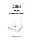
1. Introduction ............................................................................................................................... 2 1.1 Specifications ................................................................................................................ 2 2. Installation................................................................................................................................. 4 2.1 Hardware installation .................................................................................................... 4 3. Connect to the router ..................................................................................................................... 5 3.1 Setup your local network .................................................................................................... 5 3.2 Connect to the router ........................................................................................................... 8 4. Configuration .............................................................................................................................. 11 4.1 LAN Settings..................................................................................................................... 11 4.1.1 LAN IP Setting ....................................................................................................... 11 4.1.2 DHCP Setting ......................................................................................................... 13 4.1.3 DHCP Static ........................................................................................................... 15 4.2 WAN Settings .................................................................................................................... 16 4.2.1 Channel configuration ............................................................................................ 16 4.2.2 ATM setting ............................................................................................................ 25 4.2.3 ADSL setting .......................................................................................................... 26 4.3 WLAN Settings ................................................................................................................. 27 4.3.1 Basic setting ........................................................................................................... 27 4.3.2 Security setting ....................................................................................................... 28 4.3.3 Advanced setting .................................................................................................... 31 5. Advanced..................................................................................................................................... 35 5.1 Firewall ............................................................................................................................. 35 5.1.1 IP/Port filter............................................................................................................ 35 5.1.2 MAC filter .............................................................................................................. 36 5.1.3 URL filter ............................................................................................................... 38 5.1.4 ACL ........................................................................................................................ 39 5.1.5 DoS ........................................................................................................................ 43 5.2 Service............................................................................................................................... 45 5.2.1 IGMP proxy............................................................................................................ 45 5.2.3 DNS........................................................................................................................ 45 5.2.4 DDNS ..................................................................................................................... 46 5.3 Advanced........................................................................................................................... 48 5.3.1 Route ...................................................................................................................... 48 5.3.2 NAT ........................................................................................................................ 50 5.3.3 QoS ........................................................................................................................ 56 5.3.4 CWMP ................................................................................................................... 58 5.3.5 Port mapping .......................................................................................................... 60 5.3.6 Bridge setting ......................................................................................................... 62 5.3.7 Client limit ............................................................................................................. 63 6. Maintenance ................................................................................................................................ 65 6.1 Firmware upgrade ............................................................................................................. 65 6.2 Backup/Restore ................................................................................................................. 65 6.3 Password ........................................................................................................................... 65 6.4 Reboot ............................................................................................................................... 66 6.5 Time .................................................................................................................................. 67 6.6 Log .................................................................................................................................... 68 6.7 Diagnostics ........................................................................................................................ 68 6.7.1 Ping ........................................................................................................................ 69 6.7.2 Tracert .................................................................................................................... 69 6.7.3 OAM loopback ....................................................................................................... 71 6.7.4 ADSL diagnostics ................................................................................................... 72 6.7.4 Diag-test ................................................................................................................. 74 1. Introduction The 450TC3 ADSL2+ Wireless/Ethernet Router is a device with routing capability, wireless access point, multiple ADSL lines transmission mode (ADSL2+, ADSL2, T1.413, G.Dmt and G.lite) and provides 10/100Base-T Ethernet interface. The ADSL Router supports wireless 802.11n/b/g and the following security protocols: WEP, WPA, WPA2 and 802.1x. Through the ADSL access, the router can provides user with access to Internet. This user manual is mainly used to guide the user to install and configure the ADSL Router from WEB UI. 1.1 Specifications Wireless AP, Router, 4 Port Switch and Firewall Support ITU-T G.992.1 (G.dmt), ANSI T1.413, G.992.2 (G.Lite), ADSL2 and ADSL2+ Support 802.11n, compatible with 802.11b and 802.11g Up to 54 Mbps wireless operation rate 64/128 bits WEP for security WPA and WPA2 support 4 10/100MBase-T Ethernet interface (LAN) RFC-1483/2684 LLC/VC-Mux bridge/route mode RFC-1577 Classical IP over ATM RFC-2516 PPPoE RFC-2364 PPPoA ITU-T 1.610 F4/F5 OAM send and receive loop-back 802.1d Spanning-Tree Protocol DHCP Client/Server/Relay NAT RIP v1/v2 DNS Relay Agent Support DMZ, virtual server, ALG IGMP Proxy/Snooping Protection against Denial of Service attack IP Packet filtering MAC filtering URL filtering IP QoS Dynamic DNS UPnP support System log support, can record the state of the router Remote management Firmware upgrade through FTP, TFTP and HTTP Configuration backup/restore Diagnostic tools 2. Installation 2.1 Hardware installation To install the device correctly, you should prepare as follows: A RTL867x board 12V DC power RJ-45 Ethernet cable RJ-11 ADSL line COM Port cable (Optional) Then you can follow the procedures to setup the device: 1. Connect RJ-45 cable from your PC to RTL867x Ethernet Port 2. Connect RJ-11 line from RTL867x to DSLAM 3. Connect PC‟s COM port to RTL867x COM port if you have COM port cable. You can monitor the status of system and input control command from PC‟s HyperTerminal. 4. Connect the 12V DC power 3. Connect to the router 3.1 Setup your local network 1. Right click the “Network” icon on your desktop, select “properties” in the pop-up menu 2. In the following window, right click on the “Local connection” and select “properties” 3. In the pop-up dialog box, select the “Internet Protocol (TCP/IP)”, and then click the “properties” button 4. In the subsequent opening of the window, you can select "obtain IP address automatically (O) " or "Use the following IP address (S) " a) Obtain IP address automatically (O) b) Use the following IP address (S) IP address: 192.168.1.xx (xx is between 2 and 254) Subnet mask: 255.255.255.0 Gateway: 192.168.1.1 DNS Server: You can fill out your local DNS server address (ask your ISP provider) can also be the router as a DNS proxy server. Click “OK” to submit the current settings after setup is complete. 3.2 Connect to the router 1. Open IE browser, and input “http://192.168.1.1” in the address bar and press enter 2. Input username and password on the pop-up dialog to login the router The router supports different privilege of user account. The supper user and normal user. The client login with the supper user account can have the more higher privilege to management the router, such as the supper user can configure WAN interface or some advanced settings, but the normal user can just view the settings. User:admin 3. password: password If the username and password is correct, then you will see the web management pages. 4. Configuration 4.1 LAN Settings 4.1.1 LAN IP Setting 4.1.1.1 LAN IP Settings Go to the Setup->LAN page, you can configure the LAN interface of your ADSL Router. You may change the setting for IP address, subnet mask, etc.. IP address The IP address of the ADSL router‟s LAN interface, the default value is 192.168.1.1. Subnet mask The subnet mask of the ADSL router‟s LAN interface, the default value is 255.255.255.0. Secondary IP If you enable the “Secondary IP”, you should configure another IP address and subnet mask for the LAN interface. IGMP Snooping You can enable/disable the IGMP Snooping function by the select radio. Note: If you change the IP address of the LAN interface, you should use the new IP address to reconnect to the web server. The first IP and secondary IP must belong to different subnet. 4.1.1.2 Ethernet Link Speed/Duplex Mode On LAN interface setup, you can also configure each Ethernet port‟s link speed/duplex mode. LAN Port specify the LAN port number of the switch, it can be LAN1, LAN2, LAN2 and LAN4 Link Speed/Duplex Mode the mode of the selected LAN port, the default value is “Auto Negotiation” You can select a LAN port to modify its link speed/duplex mode. Note: If you configure the LAN port to a new mode, such as “100Mbps/Full Duplex”, you must make the same configuration on the PC‟s NIC which the LAN port is connected to, that is means you should configure the mode on the PC‟s NIC to be “100Mbps/Full Duplex”. 4.1.1.3 MAC Address Control The router supports the MAC address control on Ethernet port. MAC Address Control select the LAN interface on which you want to run MAC Address Control New MAC Address a MAC address to be added Current Allowed MAC Address Table it shows the current allowed MAC address list If you enable the MAC address control on an interface such as “LAN1”, then the traffic from the specified interface “LAN1” only whose MAC address matches the allowed list will be flowed, otherwise the traffic will be dropped by the router. 4.1.2 DHCP Setting Go to the Setup->LAN->DHCP page, you can configure the DHCP mode of your ADSL Router as None, DHCP Relay or DHCP Server. 4.1.2.1 None If the DHCP mode is “None”, the router will do nothing when the hosts request an IP address by DHCP protocol. 4.1.2.2 DHCP Server The DHCP Server is used to configure correct TCP/IP protocol related parameters for the computer on your local network. If you enable the DHCP Server function of the ADSL router, you can make the DHCP Server automatically configure the TCP/IP protocol parameters (such as IP address, subnet mask, gate way and DNS servers) for the computer on your local network. DHCP Mode the DHCP mode can be DHCP Server, DHCP Relay and None. Interface you can specify which interface you want to enable DHCP Server. IP Pool Range the DHCP IP pool address Default Gateway the default gateway address Max Lease Time the time that the DHCP client is allowed to maintain a network connection. Domain Name a user-friendly name that refers to the group of hosts ( subnet ) that will be assigned addresses from this pool DNS Server the IP address of DNS server used in option filed of DHCP message. 4.1.2.3 DHCP Relay If you are using the other DHCP Server to assign IP address to your hosts on the LAN, you can set the relay server‟s IP address. Relay server the IP address of the DHCP Relay server. 4.1.3 DHCP Static DHCP Static IP table shows the IP address and MAC address the client obtained from the DHCP Server. You can manually input IP and MAC address to make a static assignment. Router searches the relevant entry in this table to assign IP address according to the client‟s MAC address. If the router can‟t find a corresponding static entry, it will choose an unallocated IP address from DHCP pool assign to the client. Go to Setup->LAN->DHCP Static page, you can set the DHCP static rules. Then the client with MAC address “00:00:00:00:00:01” will be assigned an IP address of 192.168.1.64 through DHCP. 4.2 WAN Settings To enjoy the surfing, we should have the most basic configuration of the router at first. In this chapter, you can set the basic network parameters required to access the Internet. The router supports the following three common means to access: Dynamic IP access: ISP (such as China Telecom) assigns IP address to users via DHCP. Static IP access: ISP provides a static IP address to users. PPPoE dial-up access (ADSL): use PPPoE virtual dial-up connection to the Internet. 4.2.1 Channel configuration Go to Setup->WAN page, scroll to bottom & go to WAN interface table & select PPPoE change the settings as per requirement &click modify. There are many parameters on the channel configuration: VPI ATM VPI for the PVC channel VCI ATM VCI for the PVC channel Encapsulation AAL5 encapsulation mode for the PVC channel: LLC/SNAP or VC-mux Channel mode operation of the PVC channel, it can be 1483 Bridged, 1483 MER, PPPoE, PPPoA, 1483 Routed and IPoA Enable NAPT Enable or disable the NATP function of the PVC channel Enable IGMP Enable or disable the IGMP function of the PVC channel User name username of the PPP connection Password Password of the PPP connection Type The type of PPP dial-up: continuous, manual or connect-on-demand. Idle time The idle time of the PPP connection when the type is connect-on-demand. WAN IP settings : Type the type of the wan IP settings: fixed or DHCP Local IP address: the IP address of the router on the PVC channel Remote IP address: the gateway‟s IP address of the router on the PVC channel Netmask the subnet mask of the router on the PVC channel Default route the mode of the default route of the router. 1. Dynamic IP access If the channel mode of the PVC channel is 1483MER DHCP, you can obtain an IP address from your ISP service to access the Internet. You should set the VPI/VCI correctly first and select „1483 MER‟ option as the Channel mode. On WAN IP settings, set the Type as DHCP, enable the Default Route, then click the “Add” button to setup a new connection. When the connection is setup, you can see the router will obtain an IP address. 2. Static IP access If your means of access to the Internet is “Static IP” mode, enter the fixed IP address, mask, gateway address the ISP gives you. 3. PPPoE dial-up If your means of access to the Internet is “ADSL virtual dial-up” mode, enter the username and password the ISP provide to your account, and choose the type of PPP connection. If the type is “connect on demand”, you should also set the Idle Time. There are there ways of PPP type: Continuous Connect on demand Manual When the connection is setup, you can show the router will obtain an IP address after the dial-up. There are some advanced parameters of the PVC connection. Click button to enter the menu. On this page, you can change the other parameters of the PPP connection, such as bridge mode, AC-name, service name, 802.1q and VLAN ID, MTU, static IP and MACCLONE. 4.2.2 ATM setting Go to Setup->WAM->ATM page, you can configure the parameter for the ATM of your ADSL Router. You can change the settings for QoS, PCR, CDVT, SCR and MBS. 4.2.3 ADSL setting Go to Setup->WAN->ADSL page; you can configure which ADSL modulation of your modem will support. 4.3 WLAN Settings To connect to the Wireless AP, we should have the most basic configuration of the router at first. In this section, you can set the wireless network parameters required to access the AP of your WLAN interface. 4.3.1 Basic setting Go to Setup->WLAN->Basic page, you can configure the wireless parameters. Here you may enable or disable the wireless function. You can also change the wireless parameters, such as Band, SSID, Channel Width, Control Sideband, Channel Number and Radio Power. 4.3.2 Security setting Go to Setup->WLAN-> Security page, you can configure the wireless security parameters. Here you can choose the encryption method to prevent any unauthorized access to your wireless network. There are three most commonly used encryption method (a total of six encryption support), including the WEP encryption, WPA-Personal, WPA2-Personal, etc. (1) WEP If the encryption is WEP, you should click “Set WEP key” button to enter the WEP key setup page. Here you can choose the SSID type (root SSID or virtual Access Point) and set the WEP key length, key format and Default Tx key. SSID TYPE: choose the SSID you want to configure, there are can be root SSID or virtual Access Point Key Length: the length of the WEP key, it can be 64 bits or 128 bits Key Format: the format of the WEP key, it can be ASCII or hex Encryption key: the WEP key Default Tx Key: you can select one key from the follow 4 Encryption key as the current key If you want to use 802.1x authentication, you can enable this option on the checkbox. You should set the port, IP address and password for the authentication radius server. (2) WPA/WPA2 There are two WPA encryption rules: AES and TKIP, you can select anyone as the encryption. There are also two WPA Authentication mode, it can be either Enterprise (RADUIS) or Personal (Pre-Shared Key). The most commonly used authentication mode is Pre-Shared Key. You should set the Pre-Shared Key Format and Pre-Shared Key value. Pre-Shared Key Format: it can be either Passphrase or Hex (64 characters) Pre-Shared Key: the value of the Pre-Shared Key If the authentication mode is RADIUS, you should set the port, IP address and password for the authentication radius server. 4.3.3 Advanced setting (1) Wireless Advanced Settings Go to Setup->WLAN->Advanced page, you can configure the advanced parameters for your wireless LAN. Note: These settings are only for more technically advanced users who have a sufficient knowledge about wireless LAN. These settings should not be changed unless you know exactly what will happen for the changes you made on your Access Point. (2) MBSSID Setup Go to Setup->WLAN->MBSSID page, you can configure the parameters for the virtual access point. (3) Wireless Access Control Wireless access control function is used to allow or prohibit the client access to the wireless network by MAC address. Wireless Access Control Mode: it can be “disable”, “Allow Listed” or “Deny Listed”. If the mode is “disable”, it means the wireless access control function is closed; if the mode is “Allow Listed”, only the client on the list will be able to connect to you access point; if the mode is “Deny Listed”, these wireless clients on the list will not be able to connect to you access point. MAC Address: the MAC address of the client you want to allow or prohibit Current Access Control List: it show the MAC address table you configured, you can delete it as you need. (4) WDS Wireless Distribution System (WDS) is two wireless access point (AP) protocol. In the WDS wireless network, multiple AP connected by bridge or repeater, make whole local area network in wireless way. You need to entry remote AP‟s MAC Address. Note: If you want to use WDS function, you must choose AP+WDS Mode in Basic page 5. Advanced 5.1 Firewall 5.1.1 IP/Port filter Go to Firewall->IP/Port Filter page, you can set the IP/Port filter rules to secure or restrict your local network. On the front of the page, you can see the default action of outgoing/incoming connection. If the IP connection doesn‟t match any filter rules, the router will handle the connection with the default action setting. Rule Action the filter mode of this entry, it can be “Permit” and “Deny”. If the mode is “Permit”, the IP connection matches the rule will be permitted, if the mode is “Deny”, the IP connection matches the rule will be denied. WAN Interface the WAN interface you want to configure the rule. Protocol the protocol of this entry; it can be “IP”, “ICMP”, “TCP” and “UDP”. Direction the direction of this entry, it can be “upstream” and “Downstream”. Source IP Address/ Mask Address the source IP address and mask address of the entry. Dest IP Address/ Mask Address the destination IP address and mask address of the entry. Sport If the protocol is “TCP” or “UDP”, you should set the source port of the entry, it can be a single port or a port range. Dport If the protocol is “TCP” or “UDP”, you should set the destination port of the entry, it can be a single port or a port range. Enable enable or disable this filter entry. Current Filter table it shows the current filter rules. You can enable or disable or delete the filter entry. 5.1.2 MAC filter In order to management your local network better, you can use the MAC address filter function to control the internet access. Go to Firewall->MAC Filter page, you can set the MAC filtering rules. Outgoing/Incoming Default Policy the default action of outgoing/incoming connection. It can be “Deny” or “Allow”. If the connection doesn‟t match any MAC filtering rules, the router will handle the connection with the default action you have set. Direction the direction of the filter entry, it can be “Outgoing” or “Incoming”. Action the action of the filter entry, it can be “Deny” or “Allow”. If the action is “Deny”, the connection matches the filter rule will be denied, if the action is “Allow”, the connection matches the filter rule will be allowed. Source MAC the source MAC address of the filter entry, if empty means matches any source MAC address. Destination MAC the destination MAC address of the filter entry, if empty means matches any source MAC address. Current MAC Filter Table it shows the current MAC filtering rules. You can delete the entry on the list. 5.1.3 URL filter In order to manage the site control of your local LAN client, you can use URL filtering function to specify which site can‟t be accessed. Go to Firewall->URL Filter page, you can add and delete the filtered keyword. URL Blocking Capability Enable or disable the URL filtering function. If it is enabled, the access to the site which matches the keyword will be blocked by the router, if it is disabled, nothing will be done. Keyword the keyword of the site you want to block. URL Blocking Table it shows the current URL filtering entry. You can delete the selected entry. 5.1.4 ACL ACL function is used to specify which services are accessible from LAN or WAN side. Go to Firewall->ACL page, you can set the ACL entry. LAN ACL Mode choose white list or black list of LAN side WAN ACL Mode choose white list or black list of wan side Direction Select the direction of this ACL entry, it can be LAN or WAN. LAN ACL Switch you can enable or disable the ACL function on LAN side. If it is disabled, all hosts on LAN side can access the services which your router provides. If it is enabled, only the hosts on the ACL list can access the specify services. IP Address the IP address of the host, if the IP is 0.0.0.0, it means any IP. Service Allowed (LAN side) the allowed services which the host can access. It can be “any”, or any specified service, such as “web”, ”telnet”, ”ftp”, ”tftp”, ”snmp” and “ping”. If select “any”, it means the host can access all the services the router provides. If the direction is WAN, there are some different settings with LAN side. WAN Setting the setting of WAN side; it can be “Interface” or “IP Address”. If it is “Interface”, you should specify a WAN interface for this ACL entry. If the WAN setting is “IP Address”, you should specify the IP address of the host on WAN side. Service Allowed you can specify the service and opened port for this service on WAN side. The host access the specified port can obtain the specified service the router provides. Current ACL Table it shows the current ACL setting. 5.1.5 DoS The router provides a protection of Denial of Service attack. Go to Firewall->DoS page, you can configure the dos parameters. You can enable or disable the DoS prevention, and you can also specify the hack item. 5.2 Service 5.2.1 IGMP proxy IP hosts use Internet Group Management Protocol (IGMP) to report their multicast group memberships to neighbor routers. Similarly, multicast routers use IGMP to discover which of their hosts belong to multicast group. The router supports IGMP proxy that handles IGMP message. When enabled, the router will act as a proxy for a LAN host making request to join and leave multicast groups, and a multicast router sending multicast packets to multicast groups on WAN side, Go to Service->IGMP page, you can configure the IGMP proxy. Here you can enable or disable the IGMP proxy function on all WAN interface, and you can also set the parameters of the IGMP function. 5.2.3 DNS Go to Service->DNS page, you can configure the IP address of DNS server for DNS Relay. Attain DNS Automatically the device will use the DNS servers which obtained by the WAN interface via the auto-configuration mechanism Set DNS Manually configure the DNS IP address manually. 5.2.4 DDNS Dynamic Domain Name Server (DDNS) allows you to point a hostname to a dynamic or static IP address or URL. Go to Service->DDNS page, you can configure the DDNS settings. DDNS provider there are two DDNS provider to be selected in order to register your device: DynDNS.org and TZO Hostname domain name to be registered with the DDNS server Interface the WAN interface over which your device will be accessed Enable enable or disable the registration account for the DDNS server Username username assigned by the DDNS provider Password password assigned by the DDNS provider 5.3 Advanced 5.3.1 Route 5.3.1.1 Static route Go to Advanced->Route->Static Route page, you can configure the routing information. Here you can add or delete IP routes. Enable enable or disable the route entry you add Destination destination IP address. It can be a subnet IP or a host address. All zeros indicate that the route entry should be used for all destinations for which no other route is defined. Subnet Mask the network mask of the destination. Next Hop the IP address of the next hop through which traffic will forward the destination. Metric defines the number of hops between network nodes that data packets travel. Interface the WAN interface to which a static route is to be applied. The Static Route Table shows the current static route entries. 5.3.1.2 RIP RIP is an internet protocol you can setup to share routing table information with other routing devices. Go to Advanced->Route->RIP page, you can configure the RIP settings. Here you can enable or disable the RIP function. RIP enable or disable the RIP function of the router. Interface the interface on which you want to enable RIP Recv Version indicate the RIP version in which information must be passed to the device it can be accepted into its routing table Send Version indicate the RIP version this interface will use when it sends its route information to the other device The RIP Config List shows the current RIP setting of the device. 5.3.2 NAT 5.3.2.1 DMZ A Demilitarized Zone (DMZ) allows a single host on your LAN to expose ALL of its ports to the Internet. Go to Advanced->NAT->DMZ page, you can configure the DMZ settings. Enable DMZ enable or disable the DMZ function. DMZ Host IP Address the IP address of the DMZ host. 5.3.2.2 Virtual server The virtual server allows a single host on your LAN to provide the specified service to the Internet. Go to Advanced->NAT->Virtual Server page, you can configure the virtual server settings. Usual Service Name the name of this virtual server User-defined Service Name the name of this virtual server Protocol the protocol of this virtual server used WAN Setting the WAN setting of this virtual server used; it can be interface and IP address. WAN Interface the interface on which the virtual server used on WAN side WAN IP Address the IP addresses which the virtual server used on WAN side. You can access this IP and WAN port from WAN side to obtain the service. WAN Port the open port on WAN side. It can be either a single port or a port range. LAN Open Port the open port on LAN host. It can be either a single port or a port range. LAN IP Address the IP address of the host which provides the service on LAN side. If you want to setup a FTP Server on LAN host 192.168.1.72, you can configure a virtual server rule as follows: 5.3.2.3 ALG The router supports several NAT ALG and pass-Through function. Go to Advanced->NAT->ALG page, you can configure the ALG settings. Here you can enable or disable the ALG or pass-through function for each application. 5.3.2.4 Port trigger Port trigger is used to restrict certain types of data packets from your local network to internet. Use of such filters can be helpful in securing and restricting your local network. Go to Advanced->NAT->Port Trigger page, you can configure the port trigger rules. Nat Port rigger enable or disable the port trigger function on the device Application Type you can select the service from the “Usual Application Name” or define the name from “User-defined Application Name” Start Match Port / End Match port the start and end port to match Trigger Protocol the protocol to trigger the rule, it can be TCP, UDP or TCP/UDP Start Relate Port / End Relate Port the start and end relate port Open Protocol it can be TCP, UDP or TCP/UDP NAT Type it can be outgoing or incoming 5.3.2.5 FTP ALG Port FTG ALG port is used to configure the FTP server ALG and FTP client ALG ports. Go to Advanced->NAT-> FTP ALG Port page, you can configure the ftp ALG ports. If the FTP server listen the port on 2100, you can add a FTP ALG port 2100 on the device. Then the connection to the TCP destination port 2100 will be passed to the FTP ALG process, so you can use the FTP correctly. 5.3.2.6 Nat IP Mapping NAT IP mapping allows you to configure one IP pool for specified source IP address from LAN, so a packet whose source IP is in range of the specified address will select one IP address from pool for NAT. Go to Advanced->NAT->NAT IP Mapping page, you can configure the mapping rules. Type the type of this mapping rule. It can be “One-to-One”, “Many-to-One” ,“Many-to-Many” and “One-to-Many”. One-to-One: one local IP will be mapped to one global IP Many-to-One: the IP between “Local Start IP” and “Local End IP” will be mapped to a global IP Many-to-Many: the IP between “Local Start IP” and “Local End IP” will be mapped to the IP between “Global Start IP” and “Global End IP” One-to-Many: one local IP will be mapped to any of the IP between “Global Start IP” and “Global End IP” Local Start IP a local IP address Local End IP a local IP address Global Start IP a global IP address used for NAT Global End IP a global IP address used for NAT 5.3.3 QoS The router provides a control mechanism which serves traffic with different priority. The traffic is classified by criteria. A classification rule contains three configuration blocks: Qos policy, schedule mode and traffic rule. The Qos policy enables you to classify packet on the basis of various fields in the packet; the schedule mode enables you to configure which priority queue you want to use; the traffic rule enables you to assign the precedence or add marker for different streams. Go to Advanced->QoS page, you can configure the precedence for each incoming packet based on specified policy. IP QoS Enable or disable the IP QoS function on the device Schedule Mode the schedule mode of the IP QoS function, it can be strict prior or WFQ (4:3:2:1). Strict prior traffic with different priority will be send by its priority, the higher priority the traffic is, the higher priority the traffic will be send out. WFQ (4:3:2:1) traffic with different priority will be send in proportion of its priority, the four priority traffic will be send out in proportion to 4:3:2:1. ,you should configure the QoS rule. Press the “add rule” button to add a new rule. Source MAC the source MAC of the rule Destination MAC the destination MAC of the rule Source IP the source IP address of the rule Source Mask the source mask of the rule Destination IP the destination IP address of the rule Destination Mask the destination mask of the rule Source Port the source port number of the rule. If the protocol filed is not been selected or is selected as ICMP, the Source port filed can‟t be configured. Destination Port the destination port number of the rule. If the protocol filed is not been selected or is selected as ICMP, the Destination port filed can‟t be configured. Protocol the protocol of the rule. It can be TCP, UDP, ICMP and TCP/UDP. Phy port the incoming port of the rule. It indicates the physical port of the traffic is incoming. IPP/DS Field the traffic will be classified on the base of this policy. It can be based on stream, IPP/TOS or DSCP. 802.1P select an 802.1p priority level between 0 and 7. Priority select lowest priority, highest priority or other priority 5.3.4 CWMP CPE WAN Management Protocol (CWMP) is a protocol for communication between a CPE and Auto-Configuration Server (ACS). The CPE TR-069 configuration should be well defined to be able to communicate with the remote ACS. Go to Advanced->CWMP page, you can configure the TR-069 CPE. Here you may change the setting for the ACS‟s parameters. ACS parameters Enable enable or disable the CWMP URL ACS URL. User Name the username the device should use when connecting to the ACS Password the password the device should use when connecting to the ACS Periodic Inform Enable when this field is enabled, the device will send an Inform RPC to the ACS server at the system startup, and will continue to send it periodically at an interval defined in “Periodic Inform Interval” field; when this field is disabled, the device will only send Inform RPC to the ACS server once at the system startup. Periodic Inform Interval the interval to send Inform RPC Connection Request parameters: User Name username the remote ACS should use when connecting to the device Password password the remote ACS should use when connecting to the device Path the path of the device ConnectionRequestURL. Port the port of the device ConnectionRequestURL. 5.3.5 Port mapping The device provides multiple interface groups, up to five interface groups are supported including one default group. Traffic coming from one interface of a group can only be flowed to the interfaces in the same interface group. Thus, the device can isolate traffic from group to group for soma application. By default, all the interfaces (LAN and WAN) belong to the default group, and the other four groups are all empty. It is possible to assign any interface to any group but only one group. Go to Advanced->Port Mapping page, you can configure the mapping group. You can enable or disable the port mapping function of the device by the select radio button. If “Enable” radio is selected, you can configure the mapping group as follow steps: Select a group from the table, then you can see the available interface (LAN and WAN) and grouped interface list Select interfaces from the available and grouped interface list and add it to the “Interface group” using “Add>” button or delete it to the “Interface group” using “>Del” button to manipulate the required mapping of the ports Click “Apply” button to finish the configuration. 5.3.6 Bridge setting Go to Advanced->Others->Bridge Setting pages, you can configure the bridge parameters. Here you can modify the settings of MAC address aging time and enable or disable the Spanning Tree protocol, and you can also view some information on the bridge and its attached ports. Ageing Time the time for the MAC address to age out. After “Ageing Time” seconds of not having seen a frame coming from a certain address, the bridge will delete that address from the Forwarding Table. 802.1d Spanning Tree enable or disable the spanning tree protocol Click “Show MACS” button, you can see the current forwarding table of the router. 5.3.7 Client limit Client limit allows you to force how many devices can access to the internet. Go to Advanced->Others->Client Limit page, you can configure the client limit settings. Here you can enable or disable the client limit function and the maximum device to access to the internet. Client Limit Capability enable or disable the client limit function Maximum Devices the maximum number of devices can access to the Internet 6. Maintenance 6.1 Firmware upgrade The router supports the firmware upgrade from HTTP. Go to Maintenance->Update->Firmware Update page, you can upgrade the firmware to the new version. You should select the correct firmware image first, and then apply the “Upload” button. 6.2 Backup/Restore Go to Maintenance->Update->Backup/Restore page, you can save the current configuration settings to a file, and you can also restore the settings from a configuration file. 6.3 Password Go to Maintenance->Password page, you can configure the user account of the router. Here you can add user account to access the web server, and modify the password of the specified user. 6.4 Reboot Go to Maintenance->Reboot page, you can commit changes to system memory and reboot your device with different configuration. Here you can also reset the current setting to the default settings. 6.5 Time Simple Network Timing Protocol (SNTP) is a protocol used to synchronize the system time to the public SNTP server. Go to Maintenance->Time page, you can configure the system time. NTP Configuration State the current state of NTP function. Server/Server2 the IP addresses or the host name of the NTP server. Interval the interval time of NTP function Time Zone the time zone in which the device resides. When you set the NTP configuration correctly, press the button “Get GMT Time” to start the NTP function. Then you can see the GMT time obtained from NTP server. 6.6 Log Go to Maintenance->Log page, you can configure the parameters of the system log, and view the system log information. 6.7 Diagnostics The router provides several useful diagnostic tools. 6.7.1 Ping The router provides a ping command to send a message to the host you specify. Go to Maintenance->Diagnostics->Ping page, you can ping a host you wanted. Host an IP address or host name you want to ping. When you set the host, click the “PING” button to start the ping process, then the ping result will be shown. 6.7.2 Tracert The router provides a tracert command to measure the route path and transit times of packets across an Internet Protocol (IP) network. Go to Maintenance->Diagnostics->Tracert page, you can tracert a host you wanted. Host an IP address or host name you want to run trace route command NumberofTriers the number of try Timeout the time for the trace route command timeout Datasize date size of the trace route packet DSCP MaxHopCount the maximum hop count Interface the interface to which the trace route is to be applied. For example, you can set the host to www.yahoo.com, and then click the “traceroute” button to start the trace route process. Several times later, you can see the trace route result. 6.7.3 OAM loopback OAM Loopback allows you to verify the connectivity between VP/VC endpoints, as well as segment endpoints within the VP/VC. ATM uses two cell flows: F4 used in VPs and F5 used in VCs. Go to Maintenance->Diagnostics->OAM Loopback page, you can perform the loopback function to check the connectivity of the VCC. Flow type the ATM OAM flow type. The selection can be F5 Segment, F5 End-to-End, F4 Segment or F4 End-to-End. VPI the VPI number you want to do the loopback diagnostics VCI the VCI number you want to do the loopback diagnostics 6.7.4 ADSL diagnostics ADSL diagnostics allows you to diagnostics the ADSL tone. Go to Maintenance->Diagnostics->ADSL diagnostics page, you can start the ADSL tone diagnostic. Click the “Start” button to start the diagnostic, and then wait several minutes later you will see the test result. 6.7.4 Diag-test The Diagnostic Test allows you to test your DSL connection of the physical layer and protocol layer for both LAN and WAN sides. Go to Maintenance->Diagnostics-> Diag-test page, you can select an interface to run diagnostic. Click the “Run Diagnostic Test” button to start the test, and then wait several times later you can see the diagnostic result.