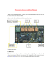
1
www.zeeltronic.com
[email protected]
updated 13.06.2008
program version: 000.070508
USER MANUAL
VCDI-30 DIGITAL IGNITION CONTROL UNIT
TECHNICAL DATA
Limit values:
- minimum revs
- maximum revs
- minimum supply voltage
- maximum supply voltage
- max. supply voltage for 1 minute
- current draw
- maximum continuous current for shift light output
- peak current for shift light output
200 RPM
20000 RPM
8 Volts
20 Volts
40 Volts
25 mAmp
1 Amp
5 Amp
Circuit is protected against reverse supply voltage (wrong connection).
Features:
- three inputs for magnetic pickups
- store and load function for 10 ignition curves
- shift light output
- external switch for changing ignition curve while riding
- easy and fast programming on the field, via hand held programmer
- programming while machine running - you can immediately see effects
- each curve can be set in 4 to 10 curve points
- advance/retard whole ignition curve
- three stage rev limit (retard timing, reduced spark, spark off)
- signal delay compensation
- instant monitoring of rev's and angle, via LCD(hand held programmer)
- fast processing for high accuracy - delays from 1us
- timing calculation for every 1 RPM change (1000, 1002, .. , 9805, 9806, ...)
-1-
1.
HOW TO ENTER MENU
VCDI must be connected to power supply. Connect programmer to VCDI and wait few
seconds for activation of programmer and then press enter. With pressing + or - you can
move through menu and with pressing enter you can choose.
You can exit menu with choosing Exit.
2.
MENU ORGANISATION
Load Settings
Save Settings
Ignition Curve
Advance
Rev Limit
Static Angle
Compensation
Pulse Width
Shift Light
Remote SW
Exit
3.
- load previously saved ignition curve set (from #1 to #2)
- save new ignition curve set (from #1 to #2)
- ignition curve parameters
- advance/retard whole ignition curve
- rev limit
- static angle (stator position)
- signal delay compensation (from pickup to spark plug)
- output signal pulse width
- shift light
- activating/deactivating external switch
LOAD SETTINGS
Enter menu and move to Load Settings with pressing + or - and then press enter .
Now you can select position number of previously saved ignition curve set, with pressing +
or - and then press enter .
4.
SAVE SETTINGS
Enter menu and move to Save Settings with pressing + or - and then press enter .
Now you can select position number to which you want to save your ignition curve set, with
pressing + or - and then press enter .
-2-
5.
Change IGNITION CURVE
Enter menu and move to Ignition Curve with pressing + or - and then press enter .
Now you are in submenu for setting ignition curve.
Submenu organisation:
Nr. of Points
- number of ignition curve points (from 4 to 10)
1)
- first ignition curve point
2)
- second ignition curve point
...
...
...
...
Exit Curve
- exit submenu
Important!
To avoid wrong processing, don't make unreasonable curve course.
Every time you make any changes to ignition curve, it is automatically saved to #0 position.
Then you can save it to any other position number from #1 to #10.
Curve Example with six curve points:
5.1.
Change NUMBER OF IGNITION CURVE POINTS
Move to Nr. of Points with pressing + or - and then press enter .
Now you can select number of ignition points, with pressing + or - and then press enter .
-3-
5.2.
Change PARAMETERS OF IGNITION CURVE POINT
Move to point you want to change, with pressing + or - and then press enter .
Now you can change rev point with pressing + or - (in 100 rpm steps) and then press
enter .
Now you can change advance angle with pressing + or - (in 0.1deg steps) and then press
enter .
6.
Set ADVANCE
With this setting is possible to advance or retard whole ignition curve. When setting is
positive then ignition curve is advanced and when setting is negative than ignition curve is
retarded. With Advance 0.0deg, ignition curve is unchanged.
Enter menu and move to Advance with pressing + or - and then press enter .
Now you can set advance with pressing + or - (in 0.1deg steps) and then press enter .
7.
Set REV LIMIT
Enter menu and move to Rev Limit with pressing + or - and then press enter .
Now you can change rev limit with pressing + or - (in 100 rpm steps) and then press
enter .
8.
Set STATIC ANGLE
Enter menu and move to Static Angle with pressing + or - and then press enter .
Now you can set static angle with pressing + or - (in 0.1deg steps) and then press enter .
More information's about static angle you can find in section 13.
9.
Set COMPENSATION
It is compensation of signal delay from pickup to spark plugs. You can check this delay with
stroboscope lamp. Without this compensation, ignition advance angle decreasing with rising
revs.
This compensation helps that advance angles in ignition curve are real (more accurate).
How to check, if compensation is correct:
First you must set flat ignition curve. Then measure with stroboscope lamp, if mark at
flywheel moving when changing revs. If mark moving then you must change compensation
delay.
Change Compensation:
Enter menu and move to Compensation with pressing + or - and then press enter .
Now you can change compensation delay with pressing + or - and then press enter .
-4-
10.
Set PULSE WIDTH
It is output pulse width (duration) in us. It affect on CDI triggering. Recommended setting is
200us or 100us.
Enter menu and move to Pulse Width with pressing + or - and then press enter .
Now you can change pulse width with pressing + or - (in 100us steps) and then press
enter .
11.
Set SHIFT LIGHT
Enter menu and move to Shift Light with pressing + or - and then press enter .
Now you can change rev point with pressing + or - (in 100 rpm steps) and then press
enter .
12.
Set REMOTE SW
Enabling or disabling external switch for changing ignition curves while riding.
Enter menu and move to Remote SW with pressing + or - and then press enter .
Now you can enable or disable external switch with pressing + or - and then press enter .
13.
MECHANICAL SETTINGS (Static Angle)
Static Angle is ignition advance angle, set with stator (generator).
Measure this angle with dial gauge. This measured Static Angle is your maximum advance
angle you can set with VCDI.
Example:
Measured Static Angle = 39.2deg
(this angle you must enter in VCDI)
Calculating mm to deg or vice versa:
-5-
14.
MONITORING
Connect programmer to VCDI and wait few seconds for activation of programmer. Fist
information displayed on the programmer is software version.
With programmer you can watch revs, calculated advance ignition angle and TPS position.
Information!
You can connect or disconnect VCDI unit from programmer any time you want, without
any harm. It is not important, if motor running or not and if power supply is connected or not.
Important!
Do not use too much force when connecting or disconnecting programmer unit!
15.
ERROR REPORTS
Two errors can be displayed:
Program Memory Error - when program memory is corrupted. With this error present,
function of program could be faulty.
EEPROM Error - when eeprom memory is corrupted. All programmable data are stored in
eeprom memory (curve, rev limit...). With this error present, function of program could be
faulty. You must check all your settings and correct changed.
-6-
www.zeeltronic.com
[email protected]
How to measure static angle?
The most accurate procedure is with dial gauge.
Apply to single and multiple cylinder engines.
Necessary tools:
- stroboscope light
- dial gauge
Follow the procedure:
Ö measure approximate static angle, just to have starting point...look at drawing below.
Anticlockwise rotation:
TDC
static angle
TRIGGER POINT
Clockwise rotation:
TDC
static angle
TRIGGER POINT
0,5mm
Ö program CDI with measured approximate static angle
Ö program CDI with flat ignition curve...16deg advance is suitable for most engines.
Ö find information about engine stroke and conrod length
Ö convert programmed flat ignition advance angle to millimetres
Example:
α =16deg (ignition advance)
L=110mm (conrod length)
R=54/2=27mm (engine stroke divided by 2)
T=1,3mm (calculated ignition advance in mm)
Equation for calculating from degrees to millimetres:
α = ignition advance in degrees
T = ignition advance in mm
R = engine stroke divided by 2 in mm
L = conrod length in mm
T = L + R ⋅ (1 − cos α ) − L2 − (R ⋅ sin α )
2
Ö remove sparkplug from cylinder head and place dial gauge
Ö find TDC (Top Dead Centre)
Ö rotate engine backwards (opposite from engine running rotation) to calculated
advance in millimetres (in example is 1,3mm) and make marks on rotor and stator
Ö remove dial gauge and place sparkplug back to cylinder head
Ö start engine and run with constant revs of about 3000rpm, or 4000rpm
Ö use stroboscope light to check, if marks on rotor and stator align
Ö adjust static angle with programmer to align marks on the rotor and stator
Result of above procedure is very accurate static angle.