1
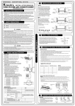
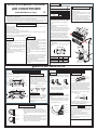
AIR CONDITIONER
A
INSTALLATION PRECAUTION
Installation in the following places may cause trouble. If it is unavoidable, please, consult
with the local dealer.
A place full of machine oil.
A saline place such as coast.
A place full of sulfide gas such as hot-spring resort.
Places where there are high frequency machines such as wireless equipment, welding
machine, and medical facility.
A place there is no combustive gases and volatile matter.
A place of special environmental conditions.
Outdoor Unit
A place where is no obstacle near the inlet
and outlet area.
A place which can bear the weight of the
indoor unit.
A place which is convenient to maintenance.
A place which provides the space around
the indoor unit as required right in the
diagram.
A place 1m or more to TV, radio instrument,
in the center of the room is perfect.
A place which is far from heat, steam and
inflammable gas.
A place, which is convenient to installation
and not exposed to a strong wind. A place
that is dry and ventilated.
A place can bear the weight of the outdoor
unit and where the outdoor unit can be held
in the horizontal position.
A place which does not allow an increase
in noise level and vibration.
A place where the operation noise and discharge air do not disturb your neighbor or
animals.
A place free of a leakage of combustible
gases.
An allowable head level at the connective
piping is less than 5m and length of the
connective piping is up less than 10m.
No any obstacle which block radiate air.
Unavailable to children.
A place, which provides the space around
the outdoor unit as required right in the
diagram.
Name of part
2
3
Clip anchor
8
5
6.35
Refrigerant Liquid side
Gas <12000Btu/h 9.53
pipe
side 12000Btu/h 12.7
Remote controller
1
6
Seal
1
7
Drain elbow
1
4
Cautions on remote controller installation
Q ty
Installation plate
Mounting screw ST3.9
1
For correct installation, read this manual before starting installation and save this manual in
a safe place for future reference.
Only trained and qualified service personnel should install, repair or service air conditioning
equipment. Users should not install the air conditioner by themselves.
All pictures are only sketches. If there is any difference between pictures in this manual and
the actual shape of the air conditioner you purchased, the actual shape shall prevail.
Indoor Unit
Part
No.
1
25-C-H
8
Please install the accessories attached with
unit correctly according to this installation
manual.
Note:
1. At least two of A, B, C aspects are free
from blocking.
2. When the Outdoor Unit is higher than the
Indoor Units, to prevent the rain from flowing
into the indoor along the connection pipe,
a downward tipping arc should be made
12c
morm or
e
before the connection pipe entering the
wall to indoor to ensure the lowest point
on the connection pipe is at outdoor.
3. The illustration above is only a sketch.
Different models would be slightly different.
Before installation, operate the remote
controller to determine its location in a
reception range.
Keep the remote controller at least 1m
apart from the nearest TV set or stereo
equipment.
Do not install the remote controller in a
place exposed to direct sunlight or close
to a heating source, such as a stove.
Note that the positive and negative poles
are right positions when loading batteries.
3
15c
2
mo
rm
ore
1
Air
Anchor bolts of out door unit installation
filte
r
The outdoor unit should not be exposed to
strong wind.
Fix the outdoor unit with 10 or 8 anchor
bolts.
12c
mo
rm
2.3m or mo
ore
4
re
A
5
Remote controller
air inlet
Air blowing
direction
B
(Split Wall-Mounted Type)
Parts Installation
A
30c
mo
60cm or more
INSTALLATION MANUAL FOR ROOM
Air blowing
direction
rm
ore
air outlet
30c
mo
Model
<12000Btu/h
12000Btu/h
B(mm)
549
276
530
290
cm
200
B
or m
60c
mo
rm
Air outlet
ore
C
Loop the
connective
cable.
If need suspending installation, consults
the corresponding requirement.
2. Connective Pipe and Drainage Installation
1. Drilling A Hole and Mounting Installation Plate
150mm or more to ceiling
Installation plate
Indoor unit outline
597
132
81
282
120mm or more
to wall
45
Right rear side
refrigerant
pipe hole 65
45
45
Left rear side
refrigerant
pipe hole 65
120mm or more
to wall
90
815
1. Install the installation plate horizontally
on structural parts in the wall with the
spaces provided around the plate.
2. In case of brick, concrete or similar
type walls, make 5mmdia holes in the
wall. Insert clip anchors for appropriate
mounting screws.
3. Fix the installation plate on the wall.
Indoor unit outline
1. Run the drain hose sloping downward. Do
not install the drain hose as illustrated
below.
Do not put the hose
end into water
2. When connection extension drain hose,
insulate the connecting part of extension
drain hose with a shield pipe
52
813
120mm or
more to the wall
120mm or more
to the wall
Rear-left pipe
hole 65mm
50
50
286
2. Drilling a hole.
55
127
98
905
( 12000Btu/h model)
90
Rear-right pipe
hole 65mm
1. As diagram above determine the pipe
hole position using the installation
plate, drill the pipe hole( 65mm),the
outside pipe hole is 5~10mm lower
than the inside one, so it slants slightly
downward.
3. Indoor Unit Installation
Upper hooker
Low hooker
Cushioning
material
1. Pass the piping through the hole in the wall.
2. Put the upper claw at the back of the indoor unit on
the upper hook of the installation plate, move the
indoor unit from side to side to see that it is securely
hooked.
3. Piping can easily be made by lifting the indoor unit
with a cushioning material between the indoor unit
and the wall. Get it out after finish piping.
4. Push the lower part of the indoor unit up on the wall,
Then move the indoor unit from side to side, up and
down to check if it is hooked securely.
Pipe cover
Left piping
Right piping
Installation Plate
150mm or more
to the ceiling Installation plate
Pipe holder
Pipe cover
Do not form a rise
(<12000Btu/h model)
40
2. Connective pipe
1. Drainage
3. Piping and bandaging
Wind the connective cable, drain hose and
wiring with tape securely, evenly as shown
below.
Because the condensed water from rare
of the indoor unit is gathered in ponding
box and is piped out of room. Do not put
anything else in the box.
Right back piping
1. For the left-hand and right-hand piping,
remove the pipe cover from the side panel.
Explain to clients that the pipe cover must
be kept as it may be used when relocate
the air conditioner to any other place.
2. For the left-hand and rear-left-hand piping,
install the piping as shown. Bend the connective pipe to be laid at 43mm height or
less from the wall.
Indoor unit outline
Connective pipe
.
.. .
. ..
.... .......................................
...................................................................
.......
............
3. Fix the end of the connective pipe.
(Refer to Tightening Connection in REFRIGRANT PIPING CONNECTION)
Ponding box
Indoor unit
CAUTION
Pipe room
Connective
cable
... . . .
.. . . ..
.. . .. .
..
..
.
. ... .. . .
Drain hose
Left back piping
43
Installation Plate and Its Dimension (Unit: mm)
1. Fix the installation plate.
ore
ore
A(mm)
1 INDOOR UNIT INSTALLATION
The Installation Plate would look like one of the
following(Depending on models):
rm
.
Connective
pipe
Wrapping belt
Connect the indoor unit first then the outdoor
unit and bend and arrange the pipe carefully.
Do not allow the piping to let out from the
back of the indoor unit.
Be careful not to let the drain hose slack.
Insulate both of the auxiliary piping.
Banding the drain hose under the auxiliary
pipe.
Do not allow the power cable and control
cable be crossed.
1 INDOOR UNIT INSTALLATION
5. Connecting Cables
4. Wiring
Prepare the power source for exclusive with the air conditioner.
The supply voltage must comply with the rated voltage of the air conditioner:
AWG(MIN.)
Plug socket and Fuse rating
Model
Power Source
Power supply cord
<12000Btu/h
60Hz 115V~
Connecting cable
14
32/25A
1. Indoor/Outdoor connection cable should be Aw18 or more.
2. Open the panel, remove the Electrical Box cover by loosening the screw (For <12000Btu/h models).
Remove the panel and Screw Covers , then loosen the screws and take down the frame
(For 12000Btu/h models).
3. Connect cables according to their marks to terminals.
Code wire
4. Wrap those cables not connected with terminals with insulation tapes,
so that they will not touch any electrical components.
18
12000Btu/h
CAUTION
40mm
10mm
Screw Cover
Frame
Perform the wiring with sufficient capacity. Installation places legally require a
short circuit isolator to be attached to prevent electrical shock.
Do not extend the power cable code by cutting.
Power voltage should in the range of 90%~110% of rated voltage.
The plug of the air conditioner takes a grounding leg, so clients should use a grounding
socket so that the air conditioner can be grounded efficiently.
The cross section area of the wiring in the table is based on the copper core inside plastics.
Frame
Panel
Terminal block of indoor unit
1
Electrical Box
Cover
2
3
4
Panel
Screw
(<12000Btu/h models)
(
To Outdoor Unit
12000Btu/h models)
2 OUTDOOR UNIT INSTALLATION
2. DRAIN ELBOW INSTALLATION
1. OUTDOOR INSTALLATION PRECAUTION
Install the outdoor unit on a rigid base to prevent increasing noise level and vibration.
Determine the air outlet direction where the discharged air is not blocked.
In the case that the installation place is exposed to strong wind such as a seaside operation
by putting the unit lengthwise along the wall or using a dust or shield plates.
Specially in windy area, install the unit to prevent the admission of wind.
If need suspending installation, the installation bracket should accord with technique requirement in the installation bracket diagram.The connection between bracket and wall, bracket
and the air conditioner should be firm, stable and reliable.
Be sure there is no obstacle which
block radiating air.
Seal
Drain elbow
Fit the seal into the drain elbow,
then insert the drain elbow into
the base pan hole of outdoor unit,
rotate 90 to securely assemble
them. Connecting the drain elbow
with an extension drain hose
(Locally purchased), in case of the
water draining off the outdoor unit
during the heating mode.
Base pan hole of
outdoor unit
Seal
Drain pipe
Strong
wind
4. WIRING CONNECTION
3. REFRIGERANT PIPING CONNECTION
2. Tightening Connection
1. Flaring
1. Cut a pipe with a pipe cutter.
90 C
Oblique Roughness
Burr
Align pipes to be connected.
Sufficiently tighten the flare nut with fingers,
and then tighten it with a spanner and torque
wrench as shown.
1. Remove the cover control from the
unit by loosening the 3 screws.
2. Dismount caps on the conduit panel.
3. Temporarily mount the conduit tubes
(not included) on the conduit panel.
4. Properly connect both the power supply
and low voltage lines to the corresponding
terminals on the terminal block.
5. Ground the unit in accordance with local
codes.
6. Be sure to size each wire allowing several
inches longer than the required length for
wiring.
7. Use lock nuts to secure the conduit tubes.
Outdoor unit
Terminal block
Ove
r 40
mm
G
Connecting
cable
Power supply
cord
Cover control
Power supply
cord
WARNING
2. Insert a flare nut into a pipe and flare the
pipe.
CAUTION
Excessive torque can break nut depending
on installation conditions.
A
Outer
diam.
A(mm)
Outer diam.
(mm)
Tightening
torque(N.cm)
Additional tightening
torque(N.cm)
1960
(200kgf.cm)
3430
(350kgf.cm)
5390
(550kgf.cm)
Max.
Min.
6.35mm
1.3
0.7
1.0
1.0
9.53mm
1570
(160kgf.cm)
2940
(300kgf.cm)
12.7mm
4900
(500kgf.cm)
6.35
9.53
12.7
1.6
1.8
Conduit panel
Be sure to comply with local codes while
running the wire from the indoor unit to
the outdoor unit.
Every wire must be connected firmly.
No wire should be allowed to touch
refrigerant tubing, the compressor
or any moving parts.
Loose wiring may cause the terminal to
overheat or result in unit malfunction.
A fire hazard may also exit. Therefore,
be sure all wiring is tightly connected.
Disconnecting means must be provided
and shall be located within sight from and
readily accessible from the air conditioner.
Connecting cable with conduit shall go
through the hole of the conduit panel.
Power supply
1
115V~60Hz
Special branch circuit breaker
(Fuse/Breaker capacity:20A)
Note : To prevent wires loosening or leaving
the Cord Clamp, please select proper cord
diameter to fill the holes on the cord clamp.
3 AIR PURGE AND TEST OPERATION
1. AIR PURGE
Choose purge method from the table:
Additional amount of
refrigerant to be charged
Connective
pipe length
Air purging
method
Less than 5m
Use vacuum
pump.
Use vacuum
pump.
5~10m
(Pipe length-5)x30g
For the R407C/R410A refrigerant models,
make sure the refrigerant added into air
conditioner is liquid form in any cases.
When relocate the unit to another place,
perform evacuation, using vacuum pump.
CAUTION IN HANDING THE PACKED VALVE
Open the valve stem until it hits against the
stopper. Do not try to open it further.
Securely tighten the valve stem cap with a
spanner or the like.
Valve stem cap tightening torque.
Gas pipe side ( 9.53): 2940N.cm (300kgf.cm)
Liquid pipe side ( 6.35): 1570N.cm (160kgf.cm)
Outdoor
unit
A
Refrigerant gas
Indoor
12.7mm ( 10000Btu/h) unit
9.53mm ( 9000Btu/h)
C
6.35mm
D
When Using the Vacuum Pump
(For method of using a manifold valve, refer to its operation manual.)
1. Completely tighten the flare nuts, A, B, C, D, connect the manifold
valve charge hose to a charge port of the low-pressure valve on the
gas pipe side.
2. Connect the charge hose connection to the vacuum pump.
3. Fully open the handle Lo of the manifold valve.
4. Operate the vacuum pump to evacuate. After starting evacuation,
slightly loose the flare nut of the Lo valve on the gas pipe side
and check that the air is entering.(Operation noise of the vacuum
pump changes and a compound meter indicates 0 instead of
minus)
5. After the evacuation is complete, fully close the handle Lo of the
manifold valve and stop the operation of the vacuum pump.
Make evacuation for 15 minutes and more and check that the
compound meter indicates -76cmHg(-1.0x10⁵Pa).
6. Turn the stem of the packed valve B about 45o counterclockwise
for 6~7 seconds after the gas coming out, then tighten the flare nut
again. Make sure the pressure display in the pressure indicator is
a little higher than the atmosphere pressure.
7. Romove the charge hose from the Low pressure charge hose.
8. Fully open the packed valve stems B and A.
9. Securely tighten the cap of the packed valve.
Manifold valve
Compound meter Pressure gauge
-76cmHg
Flare nut
Handle Lo
Handle Hi
Charge hose
Charge hose
Stopper
Cap
Vacuum pump
B
Packed valve
Half union
Valve body
Valve stem
2. GAS LEAK CHECK
Make sure no gas come out from connections
with leak detector or soap water.
CAUTION
Indoor unit
check point
D
C
B
A
Cover
Outdoor unit
check point
A: Lo packed valve B: Hi packed valve
C and D are ends of indoor unit connection.
3. TEST OPERATION
Perform test operation after completing gas leak check at the flare nut
connections and electrical safety check.
Check that all tubing and wiring have been properly connected.
Check that the gas and liquid side service valves are fully open.
1. Connect the power, press the ON/OFF button on the remote controller
to turn the unit on.
2. Use the MODE button to select COOL, HEAT(cooling & heating
modles only ), AUTO and FAN to check if all the functions works well.
3. When the amient temperature is too low(lower than 17 C), the unit can
not be controlled by the remote controller to run at cooling mode,
manual operation can be taken. Manual operation is used only when
the remote controller is disable or maintenance necessary.
Hold the panel sides and lift the panel up to an angle until it remains
fixed with a clicking sound.
Press the Manual control button to select the AUTO or COOL, the unit
will operate under Forced AUTO or COOL mode(see User Manual for
details).
4. The test operation should last about 30 minutes.
Low pressure valve
CS361-I