1
K R A ME R E LE CT R O N IC S L T D .
USER MANUAL
MODEL:
RTBUS-12
Round Table Connection Bus
P/N: 2900-300099 Rev 1
Contents
1
Introduction
1
2
2.1
Getting Started
Achieving the Best Performance
2
2
3
3.1
3.2
3.3
Overview
About HDCP—General Description
About DisplayPort—General Description
About HDMI—General Description
3
3
4
4
4
4.1
Defining the RTBUS-12
The RTBUS-12 Connecting Surface
6
7
5
5.1
5.2
5.3
Installing the RTBUS-12
Drilling a Hole in the Table
Mounting the RTBUS-12 in the Table
Connecting the Cables and Wires
8
8
9
10
6
Using the RTBUS-12
12
7
Technical Specifications
13
Figures
Figure 1: RTBUS-12 Top View
Figure 2: RTBUS-12 Connecting Surface
Figure 3: Connecting the Cables
Figure 4: RTBUS-12 to SID-X1 Cable Assembly
Figure 5: RTBUS-12 to SID-X1 Pinout
Figure 6: RTBUS-12 Boardroom Installation
6
7
10
11
11
12
RTBUS-12 – Contents
i
1
Introduction
Welcome to Kramer Electronics! Since 1981, Kramer Electronics has been
providing a world of unique, creative, and affordable solutions to the vast range of
problems that confront video, audio, presentation, and broadcasting professionals
on a daily basis. In recent years, we have redesigned and upgraded most of our
line, making the best even better!
Our 1,000-plus different models now appear in 11 groups that are clearly defined
by function: GROUP 1: Distribution Amplifiers; GROUP 2: Switchers and Routers;
GROUP 3: Control Systems; GROUP 4: Format/Standards Converters; GROUP 5:
Range Extenders and Repeaters; GROUP 6: Specialty AV Products; GROUP 7:
Scan Converters and Scalers; GROUP 8: Cables and Connectors; GROUP 9:
Room Connectivity; GROUP 10: Accessories and Rack Adapters and GROUP 11:
Sierra Video Products.
Thank you for purchasing the Kramer RTBUS-12 Round Table Connection Bus,
which is ideal for using with the Kramer SID-X1 step-in commander in
boardrooms, conference and training rooms!
RTBUS-12 - Introduction
1
2
Getting Started
We recommend that you:
•
Unpack the equipment carefully and save the original box and packaging
materials for possible future shipment
•
Review the contents of this user manual
•
Use Kramer high-performance high-resolution cables
i
2.1
Go to http://www.kramerelectronics.com to check for up-to-date
user manuals, a complete list of Kramer wall plates and module
connectors, application programs, and to check if firmware
upgrades are available (where appropriate).
Achieving the Best Performance
To achieve the best performance:
•
Use only good quality connection cables to avoid interference, deterioration
in signal quality due to poor matching, and elevated noise levels (often
associated with low quality cables)
•
Do not secure the cables in tight bundles or roll the slack into tight coils
•
Avoid interference from neighboring electrical appliances that may adversely
influence signal quality
•
Position your Kramer RTBUS-12 away from moisture, excessive sunlight
and dust
2
RTBUS-12 - Getting Started
3
Overview
The RTBUS-12 is an elegant furniture-mounted, round connection bus, designed
to be used with the Kramer SID-X1 Step-In Commander. The RTBUS-12 features
a pneumatic mechanism for pneumatic lifting and smooth closing of its lid. It is
easily installed into a table or podium top, and its interface enables you to connect
any AV input to systems installed in a room via the following pass-through
connectors:
•
1 UXGA on a 15-pin HD connector
•
1 HDMI connector
•
1 DisplayPort Connector
•
1 stereo audio on a 3.5mm connector
The RTBUS-12 also features INPUT SELECT and STEP IN buttons which can be
connected to the terminal block connectors on the rear panel of the Kramer
SID-X1 Step-In Commander (see Section 5.3.1).
The RTBUS-12 supports HDMI with Deep Color, x.v.Color™, Lip Sync, HDMI
Uncompressed Audio Channels, Dolby TrueHD, DTS-HD, and CEC.
We offer the RTBUS-12 in either a black anodized or a brushed clear aluminum
surface.
i
3.1
Note that the RTBUS-12 does not include a DVI connecter
as does the SID-X1. The DVI connector is included in the larger
sized Kramer RTBUS-22 Round Table Connection Bus.
About HDCP—General Description
The High-Bandwidth Digital Content Protection (HDCP) standard developed by
Intel, protects digital video and audio signals transmitted over DVI or HDMI
connections between two HDCP-enabled devices to eliminate the reproduction of
copyrighted material. To protect copyright holders (such as movie studios) from
having their programs copied and shared, the HDCP standard provides for the
secure and encrypted transmission of digital signals.
RTBUS-12 - Overview
3
3.2
About DisplayPort—General Description
DisplayPort (DP) is a digital display interface standard for the PC industry. It
delivers the highest resolutions and sound quality.
In addition, DisplayPort:
•
Provides a simple interface between a PC and a display, projector or TV
•
Supports 1 to 4 data pairs ("lanes") at a transfer rate of either 1.6Gbps or
2.7Gbps (device dependent)
•
Has a maximum length of 15m (49ft) for video transmission at a resolution of
1080p/60Hz and 3m (9.8ft) for full bandwidth transmission
•
Video specs include a video path that supports 6 to 16 bits per color
channel, a maximum resolution of 2560x1600 pixels and a total maximum
bandwidth of 10.8Gbps over four lanes
•
Is backward-compatible with HDMI, DVI (Digital Visual Interface) and VGA,
via an appropriate adapter
•
Version 1.1 supports HDCP
•
Supports two-way communication over its auxiliary channel between the
video source (for example, a PC) and the digital display, enabling new
functionality such as automatic configuration and one-button play
•
Replaces the interface needed between the PC and an external display, as
well as the low voltage differential signaling (LVDS) interface in notebook
computers, monitors, to connect to LCD panels
3.3
About HDMI—General Description
High-Definition Multimedia Interface (HDMI) is an uncompressed all-digital audio/video
interface, widely supported in the entertainment and home cinema industry. HDMI
ensures an all-digital rendering of video without the losses associated with analog
interfaces and their unnecessary digital-to-analog conversions. It delivers the maximum
high-definition image and sound quality in use today. Note that Kramer Electronics
Limited is an HDMI Adopter and an HDCP Licensee.
HDMI, the HDMI logo and High-Definition Multimedia Interface are trademarks or registered
trademarks of HDMI licensing LLC.
4
RTBUS-12 - Overview
In particular, HDMI:
•
Provides a simple interface between any audio/video source, such as a settop box, DVD player, or A/V receiver and video monitor, such as a digital flat
LCD / plasma television (DTV), over a single lengthy cable
SIMPLICITY - With video and multi-channel audio combined into a single cable, the
cost, complexity, and confusion of multiple cables currently used in A/V systems is
reduced
LENGTHY CABLE - HDMI technology has been designed to use standard copper cable
construction at up to 15m
•
Supports standard, enhanced, high-definition video, and multi-channel digital
audio on a single cable
MULTI-CHANNEL DIGITAL AUDIO - HDMI supports multiple audio formats, from
standard stereo to multi-channel surround-sound. HDMI has the capacity to support
Dolby 5.1 audio and high-resolution audio formats
•
Transmits all ATSC HDTV standards and supports 8-channel digital audio,
with bandwidth to spare to accommodate future enhancements and
requirements
•
Benefits consumers by providing superior, uncompressed digital video quality
via a single cable, and user-friendly connector
HDMI provides the quality and functionality of a digital interface while also supporting
uncompressed video formats in a simple, cost-effective manner
•
Is backward-compatible with DVI (Digital Visual Interface)
•
Supports CEC, two-way communication between the video source (such as a
DVD player) and the digital television, enabling new functionality such as
automatic configuration and one-button play
•
Has the capacity to support existing high-definition video formats (720p,
1080i, and 1080p, 2K and 4K), standard definition formats such as NTSC or
PAL, as well as 480p and 576p
RTBUS-12 - Overview
5
4
Defining the RTBUS-12
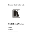
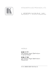
Figure 1: RTBUS-12 Top View
#
6
1
Feature
Function
Black anodized or brushed
Covers the connecting surface, leaving the table surface
aluminum semi-automatic lid neat and tidy
2
Pneumatic Mechanism
Enables automatic lifting and smooth closing of the lid
3
Outer Rim
Fits over the table surface
4
Connecting Surface
See Figure 2
5
Rubber Protectors
Protect the table surface when mounting the unit (2)
6
Mounting Screws
For securing the RTBUS-12 to the table(2)
7
Locking Butterfly Nuts
Tighten to lock the mounting butterfly screw (2)
8
Mounting Brackets
(2 units)
Place in the bracket slits after inserting the enclosure into
the table – for securing the unit to the table surface
9
Mounting Butterfly Nuts
Tighten to secure the unit to the table surface (2)
10
Mounting Bracket Slits (two
sets on each side)
Insert the mounting brackets to the slits when installing
the RTBUS-12 (see Section 5.2).
RTBUS-12 - Defining the RTBUS-12
4.1
The RTBUS-12 Connecting Surface
Figure 2 defines the connecting surface:
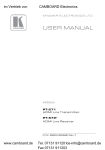
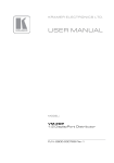
Figure 2: RTBUS-12 Connecting Surface
1
#
Feature
HDMI LED
Function
Lights green when the HDMI input is selected
2
HDMI Connector
Connect to an HDMI source
3
PC 15-pin HD
Connector
Connect to a UXGA source
4
PC LED
Lights green when the PC-UXGA input is selected
5
AUDIO 3.5mm Mini
Jack
Connects to an unbalanced stereo audio source
6
DP DisplayPort LED
Lights green when the DisplayPort input is selected
7
DP Display Port
connector
Connect to a DisplayPort source
8
INPUT SELECT Button
(with LED)
Connect to the remote terminal block of the Kramer SID-X1,
and press to cycle and select one of the inputs. The button
LED flashes with each press of the button
9
STEP-IN Button
Connect to the remote terminal block of the Kramer
SID-X1, and press to activate the input on the switcher that
the SID-X1 is connected to
10
AUDIO MODE
MANUAL/AUTO Switch
N/A
11
Lid Latch
For safely closing the lid
RTBUS-12 - Defining the RTBUS-12
7
5
Installing the RTBUS-12
To install the RTBUS-12 perform the following steps:
1. Drill a hole in the table (see Section 5.1).
2. Insert the unit through the hole and secure the unit to the table (see Section
5.2).
3. Connect the cables (see Section 5.3).
5.1
Drilling a Hole in the Table
To drill an opening in the table:
1. Using any standard cup bit drill with a diameter ranging from 88mm to 90mm
(3.47in to 3.55in), drill a hole in the table in the desired location.
Note: The thickness of the table should be 3in (76mm) or less.
2. Clean the table surface.
!
8
Take care not to damage the table. Kramer Electronics is not
responsible for any damage caused to the table.
RTBUS-12 - Installing the RTBUS-12
5.2
Mounting the RTBUS-12 in the Table
To mount the unit, follow these steps:
Step 1: Insert the RTBUS-12 into
the hole cut into the table making
sure the outer rim is firm against the
surface of the table.
Step 2: From underneath the table,
slide the mounting brackets into the
appropriate slots.
Step 3: Tighten the butterfly
mounting screws securely upward
against the table.
Step 4: Lock the mounting screws
into position with the locking
butterfly screws.
RTBUS-12 - Installing the RTBUS-12
9
5.3
Connecting the Cables and Wires
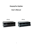
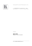
Figure 3 illustrates how to connect the cables to the underside of the unit:
Figure 3: Connecting the Cables
i
10
Note that the cables shown in Figure 3 are 50cm long and have a
MALE connector at the free end so they can be plugged directly into
the SDI-X1.
Note that the connecting surface is an integral part of the
RTBUS-12 enclosure and cannot be detached.
RTBUS-12 - Installing the RTBUS-12
5.3.1
Connecting the INPUT SELECTOR Button
The RTBUS-12 INPUT SELECT and STEP IN buttons connect (from underneath
the connecting surface) to the remote terminal block connectors of the SID-X1 via
the RTBUS-12/22 to SID-X1 cable assembly, provided with the RTBUS-12, see
Figure 4:
Figure 4: RTBUS-12 to SID-X1 Control Cable
Figure 5 shows the connection pinout:
Figure 5: RTBUS-12 to SID-X1 Control Cable Pinout
RTBUS-12 - Installing the RTBUS-12
11
6
Using the RTBUS-12
Once the RTBUS-12 is installed, you can easily customize it to your own needs by
directly plugging in the required AV equipment.
When connecting the RTBUS-12 together with the SID-X1, as illustrated in the
example in Figure 6, you can select the input to switch to the remote switcher
(for example to the Kramer VP-81SID).
In this example, the connecting surface is connected to a laptop, a DVD player
and a computer graphics source via the DP, HDMI and UXGA connectors,
respectively. A memory stick is connected to the USB connector and the laptop
has Internet access via the Ethernet connector.
From underneath the table, the DVI, DP and UXGA cables are connected to the
SID-X1 inputs and the INPUT SELECT button is wired to the REMOTE SELECT
terminal block connectors on the SID-X1 rear panel.
Press the INPUT SELECT button on the connecting surface to cycle between
inputs and select the input on the SID-X1.
Figure 6: RTBUS-12 Boardroom Installation
12
RTBUS-12 - Using the RTBUS-12
7
Technical Specifications
PORTS:
1 HDMI connector, 1 DisplayPort connector,
1 15-pin HD connector, 1 3.5mm mini jack
OPERATING TEMPERATURE
RANGE:
+5 to +45 Deg. Centigrade
OPERATING HUMIDITY RANGE:
10 to 90% RHL, non-condensing
STORAGE TEMPERATURE RANGE:
-20 to +70Deg. C.
STORAGE HUMIDITY RANGE:
5 to 95% RHL, non-condensing
DIMENSIONS:
10.5cm x 16cm (4.1" x 6.3") Diameter, H
WEIGHT:
0.85kg (1.9lbs) approx.
1.2kg (2.6lbs) approx. with mounting brackets
Specifications are subject to change without notice at http://www.kramerelectronics.com
RTBUS-12 - Technical Specifications
13
For the latest information on our products and a list of Kramer distributors,
visit our Web site where updates to this user manual may be found.
We welcome your questions, comments, and feedback.
Web site: www.kramerelectronics.com
E-mail: [email protected]
!
SAFETY WARNING
Disconnect the unit from the power
supply before opening and servicing
P/N: 2900- 300099
Rev: 1