1
20
30
40
50
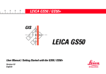
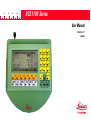
RCS1100 Series
User Manual
Version 1.2
English
Remote Controlled Surveying
Congratulations on your purchase of an
RCS1100 system !
This manual contains important safety directions (refer to section "Safety
directions") as well as instructions for setting up the instrument and operating
it. Read carefully through the User Manual before you switch on the
instrument.
2
RCS1100-1.2.0en
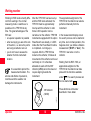
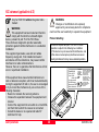
Product identification
The instrument model and the serial number of your product are indicated on
the type plate underneath.
Enter the model and serial number of your instrument in your user manual,
and always refer to this information when you need to contact your agency
or service workshop.
Model:
Serial no.:
Software version:
RCS1100-1.2.0en
3
Product identification
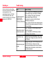
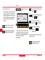
Symbols used in this Manual
The symbols used in this User Manual have the following meanings:
DANGER :
Indicates an imminently hazardous situation which, if not avoided, will
result in death or serious injury.
WARNING:
Indicates a potentially hazardous situation or an unintended use
which, if not avoided, could result in death or serious injury.
CAUTION:
Indicates a potentially hazardous situation or an unintended use
which, if not avoided, may result in minor injury and/or in appreciable
material, financial and environmental damage.
Important paragraphs which must be adhered to in practice as they
enable the product to be used in a technically correct and efficient
manner.
Symbols used in this Manual
4
RCS1100-1.2.0en
View of chapters
RCS1100-1.2.0en
Contents
6
Introduction
7
Preparation, setting up
8
Description of the system
15
Operation
17
Care and Storage
30
Safety directions
32
Technical data
41
Index
43
5
View of chapters
Contents
Introduction ....................................................... 7
Activate/Deactivate Work Area
(WORK+/WORK-) ................................................ 23
Last point stored .................................................. 23
Switching the RCS mode ..................................... 23
Lock interruption / Lock go ................................... 23
Complete display ................................................. 24
Working with the TPS1000 series .............................. 24
Local functions .......................................................... 25
Power Off .................................................................. 29
Preparation, Setting up..................................... 8
Unpacking ................................................................... 8
Fitting the RCS1100 to the reflector pole ...................... 9
Installing the TCPS26 on the tripod of the instrument . 10
TPS1100/TPS1000 interface parameters ............. 11
TPS1100/TPS1000 interface parameters ............. 11
Switching on ............................................................. 12
Trouble-shooting ....................................................... 12
Packaging and transport ........................................... 13
Batteries and chargers .............................................. 13
Charging batteries ..................................................... 14
Inserting and removing batteries ................................ 14
Care and Storage ............................................ 30
Transport and Storage .............................................. 30
Cleaning ................................................................... 30
Battery charging ........................................................ 31
Safety directions ............................................. 32
Description of the system .............................. 15
Intended use of instrument ........................................ 32
Permitted uses ..................................................... 32
Prohibited uses .................................................... 32
Limits of use .............................................................. 33
Responsibilities ......................................................... 33
Hazards in use .......................................................... 34
Electromagnetic acceptability .................................... 38
FCC statement (applicable in U.S.) ............................ 40
Description of the instrument ..................................... 15
Software concept ...................................................... 16
Operation ......................................................... 17
Allocation of keys ...................................................... 17
Working procedure .................................................... 18
RCS Searching Window ...................................... 19
Definition of a Working Area (WORKA) ............... 19
Compass .............................................................. 20
PowerSearch ....................................................... 21
Hz / V ................................................................... 21
Joystick ................................................................ 22
Contents
Technical data ................................................. 41
Radio modem ........................................................... 42
Index ................................................................. 43
6
RCS1100-1.2.0en
Introduction
The control unit, the radio modem
and the power supply are all
contained in a compact,
ergonomically-designed housing.
The incorporated radio modem is
used together with the TCPS26 radio
modem as a basic station in the
TPS1100.
Validity of the user manual
This user manual is valid for all
RCS1100 units having a built-in radio
modem.
Exceptions relating to the RCS1100
without built-in radio modem are
indicated. The present manuel
describes the software version 1.22.
Instruments in locations which are
exposed, difficult to reach, or
cramped, can be conveniently
operated with the RCS1100 control
unit.
RCS1100 stands for Remote Control
Surveying. The RCS1100 enables
survey instruments of the TPS1100
and TPS1000 series to be remote
controlled.
RCS1100-1.2.0en
7
Preparation,Setting
Introduction
up
6
Preparation, Setting up
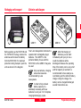
Unpacking
The RCS1100 is supplied complete
with the User Manual and with a
software diskette / CD in a padded
nylon bag. The outfit also includes
an adapter which enables the
RCS1100 to be connected to a
GLS11 reflector pole. The bag has
space for a spare GEB111/121
battery and for a TCPS26 radio
modem.
The entire equipment has been
designed for rough field conditions
but we nevertheless recommend that
you use the bags and containers
provided when you transport it over
long distances. Protect cables,
plugs, batteries and antennae
against the weather.
10
8
11
7/9
2
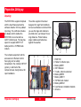
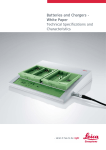
The complete equipment and the
accessories for Remote Control
Surveying can be reliably
transported in the container 667 337
(option), in which all of the
components are clearly laid out for
rapid installation.
9
8
1
Preparation, Setting up
7
6
2
3
8
5
1
2
3
4
5
6
7
8
9
10
11
1
RCS1100
Holder for reflector pole
Battery GEB71
360° Reflector
Y-cable, Antenna extension
Battery GEB70
Battery GEB111
TCPS26 radio modem
Battery GEB121
User Manual, installation diskette
Antenna
4
RCS1100-1.2.0en
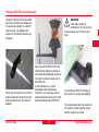
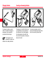
Fitting the RCS1100 to the reflector pole
Using the clamping screw provided,
secure the reflector-pole adapter at
the appropriate height on a GLS11
reflector pole. The adapter can
remain on the reflector pole during
transport.
Screw the antenna to the end of the
antenna extension and connect the
antenna extension to the reflector
adapter.
RCS1100-1.2.0en
WARNING:
If the radio modem is
switched on, do not carry the
antenna closer than 15 cm to your
body.
Now connect the RCS1100 to the
reflector-pole adapter by lining up
the marks and tightening the screw.
Connect the antenna extension to
the RCS1100.
At short distances, or under
favourable radio transmission
conditions, you can leave out the
antenna extension and connect the
antenna directly to the RCS1100.
Connecting the RCS1100 (lining up
the marks on housing and adapter)
The angle bracket and the position of
the antenna socket together ensure
that the antenna is vertical.
9
Preparation,Setting up
6
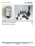
Installing the TCPS26 on the tripod of the instrument
If the RCS1100 is secured in another
manner, make sure that the antenna
is vertical, otherwise the
transmission range will be restricted.
1
2
1
2
Connect the following to the tripod of
the instrument: The TCPS26 radio
modem, the antenna extension with
antenna, and the GEB70 or GEB71
external battery. Make sure that the
antenna can transmit freely in the
direction of work. The TCPS26 radio
modem must be configured as the
BASE modem.
Reflctor pole, completely set up
Preparation, Setting up
Using the Y-cable, connect the
survey instrument, the battery and
the TCPS26 radio modem. Connect
the antenna extension to the
TCPS26.
10
3
1 Antenna extension
2 TCPS26 radio modem
3 GEB70 external battery
RCS1100-1.2.0en
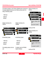
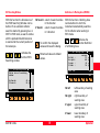
TPS1100/TPS1000 interface parameters
Switch on the RCS Mode on TPS1100/ TPS1000
The interface parameters on the TPS1100 / TPS1000 must be inspected and
if necessary adjusted to the those for the TCPS26, which were set in the
factory to the following values:
Setting the interface on the
TPS1100:
MAIN\ Communication mode
MAIN\ RCS mode
Setting the interface on the
TPS1100:
Switches to Remote Control
mode.
MAIN\ Communication mode
CONF\
SYSTEM CONFIG.
CONF\ GSI-COMMUNICATION
Confirm with "YES".
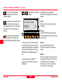
Setting the interface on the
TPS1000:
MC
MAIN\ Configuration
MAIN MENU: PROGRAMS
Do you want to switch ?
MC
MC
Setting the interface on the
TPS1000:
MC
Main menu
MC
MAIN\ Configuration
19200 baud
8 data bits
No parity
MAIN\
Main menu
MC
MAIN\
6
Set the following values
19200 baud
8 data bits
No parity
Set the following values:
EXTRA\
EXTRA FUNCTIONS
EXTRA\
19200 baud
8 data bits
No parity
MC
MAIN MENU: PROGRAMS
MC
MAIN\ RCS parameters
EXTRA FUNCTIONS
Switches to Remote Control
mode.
Do you want to switch ?
The remaining values are not relevant.
RCS1100-1.2.0en
For details, refer to the TPS1000
Systems Handbook.
11
Confirm with "YES".
Preparation,Setting up
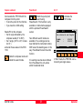
Switching on
Trouble-shooting
After all connections and settings
have been inspected, the RCS1100
can be switched on. This
automatically brings the TPS1100
into the RCS mode. After a few
seconds, the display of the TPS1100
appears on the RCS1100.
Error
Preparation, Setting up
Cause / remedy
Case 1 - Green LED on TCPS26 does not shine:
Inspect battery charge, and cables for TCPS26
Case 2 - Message "No signal" on RCS1100:
No data transfer when
Inspect battery charge in RCS1100
starting up (short
or possible link numbers for RCS1100 and
distance between
TCPS26 are not the same.
TCPS26 and RCS1100)
Case 3 - Green LED shines and message appears
on RCS1100: Set interface paarmeters correctly on
TPS and TCPS26.
Data transfer possible,
but transmission fault
Case 1 - Red LED on TCPS26 flashes: Inspect
interface parameters.
Case 2 - Red LED on TCPS26 does not flash:
Connecting cable is defective
Data transfer is very
slow
Disturbance from other transmitters in the 2.4 Ghz
frequency band: Change link number in RSC1100
and TCPS26.
Interruption during data
transfer
Message "No signal" on RCS1100:Operation is at
the limit of the range, or there is no visual
communication between RCS1100 and TCPS26.
Establish visual communication, reduce distance,
use antenna extension.
12
RCS1100-1.2.0en
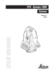
Packaging and transport
Batteries and chargers
GEB111
Before packing up the RCS1100 and
the TCPS26 in the bag, unscrew the
antennae and remove the battery
from the RCS1100. For maximum
protection during transport, pack the
units as shown in the diagram.
Your Leica Geosystems instrument is
operated with rechargable plug-in
batteries. The GEB111 is the
preferred battery for use with the
RCS1100, but the GEB121 may also
be used.
Only use batteries, charging
sets and accessories
recommended by Leica
Geosystems.
In order to fully exhaust
battery capacity it is
absolutely necessary with new
batteries to carry out 3 to 5 complete
charging/discharging cycles.
RCS1100-1.2.0en
13
GEB121
1100z06
T100Z72
6
After first charging of
batteries you can start
immediately with your job. As a
result, the batteries will be
discharged. Because the operating
time of the battery can be very short
until full capacity is reached it is
recommended to have ready a second battery and the GKL122 battery
charger. Using the charger, the
battery can be charged/discharged
several times before use.
Preparation,Setting up
T100Z74
Tcs11z02
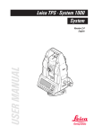
Inserting and removing batteries
Tcs11z01
Charging batteries
To charge the battery, use the
GKL111 or GKL122 charger as
described in the instructions
provided with that charger.
The chargers are not
intended for outdoor use.
Adhere to the safety directions.
Preparation, Setting up
The battery for the RCS1100 fits into
a compartment on the underside of
the instrument. Push it fully against
the side opposite to the catch and
then click it into position on the same
side as the catch.
14
To remove the battery, hold it to
prevent it from falling and pull out the
lever of the catch by about 2mm.
RCS1100-1.2.0en
Description of the system
Description of the instrument
The RCS1100 can remotely control
almost all of the functions and
applications of TPS1100 and
TPS1000 series instruments.
The RCS1100 consists of the
keyboard and LCD display from the
TPS1100, the radio module of the
TCPS26, and the power unit.
Because its keyboard and LCD are
the same as those in the TPS1100,
the RCS1100 is operated in exactly
the same way. If the TPS1000 is
used, the keyboard template for
assigning the keys is applied.
RCS1100-1.2.0en
6
The functions and settings of the
RCS1100 are called by keeping the
illumination key or function key
pressed for at least two seconds:
1. Brightness of LCD display
2. Contrast of LCD display
3. Configuration of beep
4. Heating for LCD display
5. Sleep mode
6. Configuration of internal radio
module and of TCPS26
7. Configuration of serial interface
8. Language
9. Operating mode of TPS1100
15
The status of the battery, and the
radio contact, are monitored and can
be displayed. If the radio contact is
interrupted for a long period, or if the
battery charge sinks below a certain
level, a warning is displayed.
Description of the system
7
8
Software concept
The RCS1100 has loadable software
covering the requirements for
controlling the TPS1100/TPS1000
and the local functions. The software
also includes all available language
elements for the local functions. The
software is loaded with the up-load
function of the SurveyOffice in the
same way as for the TPS1100. The
charging procedure is controlled
entirely by the SurveyOffice.
Description of the system
New languages are
continually being added for
the local functions of the RCS1100. If
you cannot find the language which
you want, contact your Leica Geosystems agency.
16
RCS1100-1.2.0en
Operation
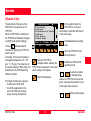
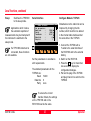
Allocation of keys
The key
activates special
functions for aligning the TPS1100
with the prism.
The shape of the search window is
rectangular (default size: Hz = 30
gon, V = 15 gon). The dimension of
the search window in RCS mode can
be defined in the "RCS Searching
Window" function.
01
02
03
04
05
06
Program selection
Free Station
Resection
Orientation & Ht.Transfer
Stakeout
Tie Distance
Remote Height
COMPS
PS
JSTCK WORK+ LAST
RCS+
Hz/V
WORKA
QUIT
In the joystick mode, the
TPS1100 can be turned
horizontally or vertically with the aid
of the cursor keys.
Activate/deactivate working
area.
Turns the TPS1100 to the
last point stored.
Sets the TPS1100 to
compass mode, enabling the
TPS1100 to be targeted on the prism
with the help of a compass.
Starts PowerSearch.
The target functions are required :
• to achieve the first LOCK
• for LOCK replacement in the
event of LOCK loss (through
longer viewing interruptions).
RCS1100-1.2.0en
MC
The allocation of the keys on the
RCS1100 is the same as on the
TPS1100.
When the RCS1100 is switched on,
the TPS1100 automatically changes
to LOCK mode (prism tracking).
6
Switches on/off the RCS
operating mode.
By entering relative
or absolute angle
values, the TPS1100 can be turned
by the corresponding amount or set
to the angle value required.
Define a working area.
17
Operation
7
8
15
Working in RCS mode is hardly different from working in the normal
measuring mode. A switchover is
possible on the TPS1100 at any
time. The great advantages of the
RCS are:
• one-person operation is possible
• when surveying you are at the site
of the action, i.e. where the points
are being recorded or set out
• you do not have to assess the
situation from the instrument
location.
It is essential to protect the
measurement location. The
actions and effects of personnel,
machines and the weather can
damage the instruments.
After the TPS1100 has been set up
and the RCS mode activated, the
TPS1100 must be approximately
lined up with the reflector in order
that a LOCK operation can be
carried out on the reflector. TPS1100
instruments equipped with the option
PowerSearch are already in LOCK
mode after the PowerSearch routine
is completed - no lining up is
required. After the TPS1100 has
locked on the reflector, it follows all
movements of the reflector and is set
centrically on it. It is therefore
advisable to work with the 360°
reflector (GRZ4) since this does not
require aligning towards the
instrument.
The approximate alignment of the
TPS1100 to the reflector can also be
performed manually from the
instrument.
In the measurement display screen
the search process can be started at
any time. As in normal operation, this
happens when you initiate a distance
measurement ("DIST" or "ALL"). The
TPS1100 now locks on to the
reflector.
Starting from the RCS 1100, an
approximate alignment of the
TPS1100 to the reflector can take
place with the functions available
under
. The search process can
then be started with
.
These functions will be later
described in more detail.
360°reflector
(GRZ4)
1000Z25
5
Working procedure
Operation
18
RCS1100-1.2.0en
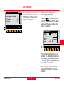
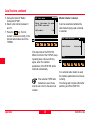
Definition of a Working Area (WORKA)
With this function the dimensions of
the RCS Searching Window can be
defined. If an automatic reflector
search is started by pressing ALL or
DIST in RCS mode, a search window
with the predetermined dimensions
is scanned at the current position of
the telescope.
/
/
Activates the
function RCS
Searching window.
Hz Search:
V Search :
CONT
40
20
To confirm the displayed
values and leave the dialog.
Returns all values to default
values.
MC
...\ RCS Searching Window
Define size of searching
window
Hz Search extent of search window
in Hz-direction
V Search extent of search window
in V-direction
With this function a Working Area
can be defined in which the
instrument automatically searches
for the reflector when working in
RCS mode.
Activates the
function Definition
of a Working Area.
...\
Def. Working Area
current
Hz left :
171
Hz right :
243
V upper :
90
V lower :
114
CONT
g
g
g
g
SHOW
QUIT
g
g
Hz left
DEFLT
QUIT
Hz right
V upper
V lower
RCS1100-1.2.0en
DEF
MC
RCS Searching Window
19
left boundary of working
area
right boundary of
working area
upper boundary of
working area
lower boundary of
working area
Operation
6
7
8
15
5
Definition of a Working Area (WORKA), cont.
Compass
To confirm the displayed
values and return to the
previous dialog.
Activates the compass
mode.
RCS\
To define a new working area
by pointing the telescope to
two opposite corners of the working
area (left corner - opposite right
corner).
Orient. with comp.
Enter compass readings
Hz-Compass:
V-KCompass:
55 °
-15 °
CONT
QUIT
To position the telescope to
the upper left / lower right
corner of the defined Working Area.
In order to use the compass mode
we recommend you to use a handheld compass with 360° rotatable Hz
circle and incorporated V circle, e.g.
RECTA DP6 or SILVA Ranger 15 /
25.
Compass mode is suitable for
aligning the TPS1100 over longer
distances.
Operation
To establish the link between
TPS1100 and compass, proceed as
follows:
20
Step 1:
Perform the Hz orientation on the
TPS1100.
Step 2:
Turn the TPS1100 until Hz shows
0.000 (irrespective of the angle units
being used).
Step 3:
Look into the telescope of the
TPS1100 and select a prominent
target.
Step 4:
Aim the compass at the same prominent target and turn the Hz circle of
the compass until the compass
needle is at 0° or at N (north). Do
not turn the Hz circle again.
RCS1100-1.2.0en
Hz / V
Compass, continued
PowerSearch
Aim towards the TPS1100 with the
compass from the prism:
• To lock the prism for the first time
• if you lose the LOCK setting.
Starts the quick prism
search using
PowerSearch. This function is only
available on instruments equipped
with the optional PowerSearch
sensor.
Read off from the compass:
• the Hz angle indicated by the
compass needle (0° to 360°)
• the V angle (+90° to -90°, horizontal = 0°)
and enter these values in the RCS
1100.
Quits the compass mode and
starts the search mode.
RCS1100-1.2.0en
Two different search modes are
available. If no working area has
been defined the instrument rotates
360º around its standing axis. In this
way, PowerSearch scans the entire
horizon.
If a working area has been defined,
then PowerSearch is only active
within the defined limits.
21
Activates the
Hz/V mode.
6
7
RCS\
HZ/V
Set relative Hz- and V-angles
∆ Hz
Hz/∆
∆V
V/∆
CONT
:
:
8
0°00'00"
0°00'00"
15
ABS
QUIT
In Hz/V mode, the TPS1100 can be
turned by set angle values.
Operation
5
Joystick
Activates the joystick
mode.
The input options are:
• absolute angle values which relate
to the orientation of the TPS1100.
• relative angle values which cause
the TPS1100 to turn away from its
present position by the amount
entered.
RCS\
Joystick mevement
:
:
left).
right (
12°15'30"
91°30'25"
left).
Turns telescope slowly
CONT
QUIT
Quits the Hz/V mode and
starts the search mode.
Switches between absolute
(ABS) and relative (REL).
right (
Turns telescope rapidly to the
User cursor keys
Hz/∆
∆ Hz
∆V
V/∆
Turns telescope slowly to the
upwards (
downwards).
Turns telescope rapidly
In the joystick mode, the cursor keys
on the RCS 1100 can be used to turn
the TPS1100. The EGL guide light, if
available, is switched on
automatically.
upwards (
downwards).
To stop the rotary movement, press
any cursor key.
Quits joystick mode and
starts search mode.
Operation
22
RCS1100-1.2.0en
Activate/Deactivate Work Area (WORK+/WORK-)
Activates the function
activate/deactivate
working area.
If the instrument is in RCS mode and
the determined working area is
activated then the entire working
area is scanned for the reflector if
the target was not found by the
standard search method at the
current position of the telescope.
If the working area is deactivated
only the standard search methods at
the current position of the telescope
are performed.
The instrument follows the reflector
even if the reflector is outside the
Working Area.
If the target is lost outside
the Working Area a local
search will be started. If the reflector
was not found the predefined
Working Area is scanned.
RCS1100-1.2.0en
Lock interruption / Lock go
On instruments with the optional
PowerSearch, the working area can
be used to limit PowerSearch to a
certain area and when activated,
PowerSearch only scans within the
defined limits.
Last point stored
Activates the LAST
function.
If the LOCK mode is lost, this
function can be used to turn the
TPS1100 back to the last point
stored. When the movement is
complete, the TPS1100 automatically
starts to search for the prism.
Activates the lock
interruption/relock.
This function serves to interrupt the
LOCK mode and later to reinstate it,
e.g. if the prism is placed on the
ground during stakeout or if the
TPS1100 is also to be targeted on a
second prism.
If this function is called up in
the RCS-mode the Joystick
dialog is automatically started. The
ATR remains active, i.e. if the
reflector reappears in the field of
view it is immediately relocked.
Switching the RCS mode
Switches on/off the
RCS mode.
For using the remote control the
RCS mode must be switched on.
23
Operation
6
7
8
15
Complete display
Hold for min. 2 seconds.
The complete contents of the
respective display is transfered if the
display is incomplete due to
disturbances to the radio link. The
function is only available on the
RCS.
5
Working with the TPS1000 series
The instrumentation is set up and
prepared in the same way as the
TPS1100. The keyboard and display
differ somewhat from those in the
other series and so a keyboard
template must be used with the
RCS1100. The presentation in the
RCS1100 of the dialogues from the
TPS1000 differs slightly, but this
does not in any way restrict the
operation.
The functions specific to the RCS
are described in detail in the
appropriate section of the user
manual for the TPS1000.
The greatest differences are in the
display of the icons; this is due to the
different dimensions of the display.
The time, and the battery status of
the TPS1000, are displayed
alternately in the title line.
Operation
24
Instead of two lines of three status
fields, one line of four status fields is
displayed on the right-hand margin.
1. The first position normally shows
the status for the memory card.
The operating mode is not shown,
because remote control is only
possible in RCS mode.
2. The second position normally
shows the telescope face. If the
compensator cannot be read out
at this time, the current display of
the telescope face is
superimposed. If the compensator
has been switched off, the
symbols for the compensator and
for the telescope face are
displayed alternately.
3. The third position shows the
status symbol for the automatic
target recognition (LOCK).
4. The last position shows the key
mode.
RCS1100-1.2.0en
Local functions
COMPASS
MC
RCS\
Enter compass readings
Hz-Compass:
V-Compass :
I
55 °
-15 °
The operating concept for the local
functions is the same as in the
TPS1100 and is therefore not
explained at this point.
CONT
QUIT
Illumination, battery and
monitoring of functions
6
Keep the
key pressed down for
more than two seconds. The battery
status and the quality of the radio
link are displayed.
\ Illumination,...
Battery
:
Radio: OK
Display
:
X
Contrast : 70%
Heating
:
X
Sleep
:
5
Minutes
Beep
: Loud
CONT DISP+ HEAT+
DEFLT
The contrast of the display can be
altered. The display illumination and
the heating at temperatures below 10°C (high power consumption!) can
be switched on and off.
The key beep and the automatic
switchoff of the RCS1100 can be
altered.
RCS1100-1.2.0en
25
Operation
7
8
15
5
Local functions, continued
Configurations and settings
Select Language
Keep the
key pressed down for
more than two seconds. The
available functions are displayed.
Select the required language from
the list field.
CONT
RCS\
Select
TPS1100 Mode
Switch TPS1100:
Set Language
Language
:
MC
RCS\
RCS\ Configuration
1 Select Language
2 Select TPS1100 Mode
3 Serial Interface
4 Configure Modem /TCPS26
5 Modem internal/external
6 GeoCOM RCS
Select TPS1100 Mode
RCS Mode
CONT
ENGLISH
Select the mode for the TPS1100
CONT
INFO
The choice of language is
valid only for the local
functions.
RCS Mode: The TPS1100 can be
operated in RCS mode.
GeoCOM: The TPS1100 can be
operated in GeoCOM
mode (transparent
mode).
OFF:
Switches off the
TPS1100.
Data may be lost if the
TPS1100 is switched off
during an application.
Operation
26
RCS1100-1.2.0en
Local functions, continued
Switches the TPS1000
to the sleep mode.
Applications which involve
the automatic repetition of
measurements may be interrupted if
the instrument is switched to the
sleep mode.
Serial Interface
Configure Modem / TCPS26
SERIAL INTERFACE
Set parameters:
Baud rate
:
Parity
:
Terminator
:
Data bits
:
Stop bit
:
MC
Sleep:
19200
NONE
CR/LF
8
1
CONT
If a TPS1000 instrument is
connected, these functions
are not available.
Set the parameters in accordance
with requirements.
The standard parameters for the
TCPS26 are:
Baud 19200
Data bits 8
Parity none
Disturbances to the radio link can be
improved by changing the link
number, which must then be altered
in the internal radio module and at
the same time in the TCPS26.
1. Connect the TCPS26 with a
Y-cable to the serial interface of
the RCS1100 and to the external
battery.
2. Switch on the RCS1100.
3. Press the
key for more than
two seconds to display the
configuration dialogue.
4. Pull out the plug of the TCPS26
and plug it back in to switch on the
TCPS26.
To ensure the correct
transfer of data, the settings
on the TPS1100 and on the
RCS1100 must be the same.
RCS1100-1.2.0en
27
Operation
6
7
8
15
Local functions, continued
RCS\ Radio modem
MC
Select link number for modem
and TCPS26 connected.
Link number:
0
Modem internal / external
It can be ascertained whether the
radio modem being used is internal
or external.
CONT
RCS\ Modem Selection
Radio Modem:
5
If the baud rate of the RCS1100
differs from that of the TCPS26, keep
repeating step 4 above until they
agree, when the interface
parameters of the RCS1100 will be
matched automatically.
If two external TCPS radio
modems are used, these
must be set in turn to the same link
number.
Operation
28
MC
5. Call up the function "Radio/
ConfigureTCPS26".
6. Select a link number between 0
and 15.
7. Press the
key. The link
number is now set correctly in the
internal radio module and in the
TCPS26.
internal
CONT
If an external radio modem is used,
the interface parameters must be set
correctly.
This change will only take effect after
switching on/off the RCS1100.
RCS1100-1.2.0en
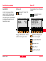
Local functions, continued
There are different Power Off options
available.
Activates the function Software Info.
RCS\
Software Info
Instr.Name :
Serial no. :
System vers:
RCS1100
10004
1.22
CONT
Activates the function
Power Off.
OFF
OFF+
SLEEP
SLP+
CONT
CONT
Displays instrument name, serial no.,
and the current system version.
Power Off
RCS switches off
RCS & TPS off
RCS sleep mode
RCS & TPS sleep mode
Continue operation
SLP+ SLEEP OFF+
OFF
Exits Power Off display and
returns to the program.
Sleep mode RCS.
RCS & TPS off.
Only RCS switches off.
29
8
15
Sleep mode RCS & TPS.
RCS1100-1.2.0en
6
7
MC
In order to load a new software
version the RCS1100 must be set
into the GeoCOM mode. In most
cases this happens automatically if
the Software Upload of the Leica
SurveyOffice is used.
Software Info
MC
GeoCOM RCS
Power Off
Operation
5
7
Care and Storage
Transport and Storage
Cleaning
When transporting or
shipping the equipment
always use the original Leica Geosystems packaging (transport case and
shipping cardboard).
Always remove the battery
before transporting the
instrument. Pack the battery so that
no short-circuiting can occur.
Never carry the instrument loose in a
road vehicle. It can be affected by
shock and vibration. Always carry it
in its in its transport case or bag and
secure it.
When storing the
equipment, particularly in
summer and inside a vehicle, take
the storage temperature limits (40°C to + 70°C / -40°F to +158°F)
into account.
When transporting the instrument by
by rail, aircraft or ship use the Leica Geosystems original packaging
(transport case or shipping
cardboard) or another suitable
packaging securing the instrument
against shock and vibrations.
Care and Storage
If the instrument becomes
wet, leave it unpacked.
Wipe down, clean, and dry the
instrument (at not more than 40 °C/
108°F), transport case, foam inserts,
and accessories. Pack up the equipment only when it is perfectly dry.
30
• Blow away any dust before
cleaning.
• Use only a clean, soft and lint-free
cloth for cleaning. If necessary,
moisten the cloth with pure
alcohol.
Use no other liquids; these may
attack polymer
components.
Cables and plugs
Keep plugs clean and dry.
Blow out any dirt lodged in the plugs
of the connecting cables.
If you unplug connecting cables
during the measurement, you may
lose data.
Always switch off the instrument
before removing the connecting
cables.
RCS1100-1.2.0en
Battery charging
Only use batteries, charging
sets and accessories
recommended by Leica
Geosystems.
In order to reach full
capacity with the new
batteries it is essential to carry out
three to five complete charging/
discharging cycles.
RCS1100-1.2.0en
For further information, please refer
to the section "Inserting and
removing batteries", or to the
instructions provided with the battery.
6
7
8
T100Z72
WARNING:
Use a battery charger in a
dry room only, never
outdoors. Charge batteries only at an
ambient temperature between +10°C
and +30°C ( 50°F to 86°F ). We
recommend a temperature of 0°C to
+20°C (32°F to 68°F) for storing the
batteries.
GEB111
15
17
Your Leica Geosystems instrument is
operated with rechargable plug-in
batteries. The GEB111, an NiMH
battery, is the preferred one for use
with the RCS1100, but the GEB121
may also be used.
31
Care and Storage
5
Safety directions
Intended use of instrument
The following directions should
enable the person responsible for
the RCS1100, and the person who
actually uses the instrument, to
anticipate and avoid operational
hazards.
Permitted uses
Prohibited uses
The RCS1100 is intended for the
following applications:
• Activation of the RCS1100 without
previous instruction
• Use outside of the intended limits
• Disabling safety systems and removal of hazard notices
• Opening the instrument using
tools (screwdriver, etc.), unless
this is specifically permitted for
certain functions
• Modification or conversion of the
instrument
• Activation after misappropriation
• Use with accessories from other
manufacturers without the prior
express approval of Leica Geosystems (only the antennae provided
by Leica may be used)
• Inadequate protection at the
measurement location (e.g. when
carrying out measurements on
roads)
• Control of machines, objects in
motion or similar with the
RCS1100 Remote Control System
The person responsible for the
instrument must ensure that all users
understand these directions and
adhere to them.
7
• Starting of the RCS1100
• Remote control of TPS models
• Recording, editing and managing
of measurements
• Data transmission to external
appliances (transparent mode)
• Running of applications programs
• Transmitting and receiving
measurements
6
Safety directions
32
RCS1100-1.2.0en
Prohibited uses, continued
Limits of use
Responsibilities
WARNING :
Adverse use can lead to
injury, malfunction, and
damage.
It is the task of the person
responsible for the instrument to
inform the user about hazards and
how to counteract them. The
RCS1100 is not to be used until the
user has been properly instructed
how to use it.
Environment:
Suitable for use in an atmosphere
appropriate for permanent human
habitation: not suitable for use in aggressive or explosive environments.
Use in rain is permissible for limited
periods.
Area of responsibility for the
manufacturer of the original
equipment Leica Geosystems AG,
CH-9435 Heerbrugg (hereinafter
referred to as Leica Geosystems):
6
Leica Geosystems is responsible for
supplying the product, including the
user manual and original
accessories, in a completely-safe
condition.
8
Refer to section "Technical data".
Responsibilities of the
manufacturers of non-Leica Geosystems accessories:
The manufacturers of nonLeica Geosystems
accessories for the RCS1100 are
responsible for developing,
implementing and communicating
safety concepts for their products,
and are also responsible for the
effectiveness of those safety
concepts in combination with the
Leica product.
RCS1100-1.2.0en
33
Safety directions
7
15
17
26
5
7
6
Responsibilities (continued)
Hazards in use
Responsibilities of the person in
charge of the instrument:
WARNING:
The person responsible for
the instrument must ensure
that it is used in accordance with the
instructions. This person is also
accountable for the training and
deployment of personnel who use
the instrument and for the safety of
the equipment when in use.
WARNING:
The absence of instruction,
or the inadequate imparting
of instruction, can lead to incorrect or
adverse use, and can give rise to
accidents with far-reaching human,
material, financial and environmental
consequences.
Precautions:
All users must follow the safety
directions given by the manufacturer
and the directions of the person
responsible for the instrument.
The person in charge of the
instrument has the following duties:
• To understand the safety
instructions on the product and the
instructions in the user manual.
• To be familiar with local
regulations relating to accident
prevention.
• To inform Leica Geosystems
immediately if the equipment
becomes unsafe.
• To ensure that the national laws,
regulations and conditions for the
operation of radio transmitters are
respected.
Safety directions
34
WARNING:
The charger must not be
used in damp or inclement
conditions. If moisture penetrates the
charger, the user may receive an
electric shock.
Precautions:
Use the charger only indoors, in dry
rooms. Protect it from damp. If the
charger is damp, do not use it.
RCS1100-1.2.0en
Hazards in use, continued
WARNING:
If you open the charger,
either of the following actions
may cause you to receive an electric
shock:
• Touching live components
• Using the charger after incorrect
attempts to carry out repairs.
Precautions:
Do not open the charger yourself.
Only a Leica Geosystems-approved
service technician is entitled to repair it.
RCS1100-1.2.0en
DANGER:
Because of the risk of
electrocution, it is very
dangerous to use reflector poles in
the vicinity of electrical installations
such as power cables or electrical
railways.
Precautions:
Keep at a safe distance from
electrical installations. If it is essential to work in this environment, first
contact the safety authorities
responsible for the electrical
installations and follow their
instructions.
35
WARNING:
By surveying during a
thunderstorm you are at risk
from lightning.
Precautions:
Do not carry out field surveys during
thunderstorms.
6
WARNING:
During target recognition or
stakeout procedures there is
a danger of accidents occurring if the
user does not pay attention to the
environmental conditions around or
between the instrument and the
target (e.g.: obstacles, excavations
or traffic).
Precautions:
The person responsible for the
instrument must make all users fully
aware of the potential dangers.
15
Safety directions
7
8
17
26
5
7
6
Hazards in use, continued
WARNING:
Inadequate securing of the
surveying site can lead to
dangerous situations, for example in
traffic, on building sites, and at
industrial installations.
Precautions:
Always ensure that the survey site is
adequately secured. Adhere to the
regulations governing accident
prevention and road traffic.
WARNING:
If computers intended for
use indoors are used in the
field, there is a danger of electric
shock.
Precautions:
Adhere to the instructions given by
the computer manufacturer with
regard to field use in conjunction with
Leica Geosystems instruments.
CAUTION:
With the remote control on
TPS models, it is possible
that extraneous targets will be picked
out and measured.
Precautions:
When measuring in remote control
mode, always check your results for
plausibility.
Safety directions
36
CAUTION:
If the accessories used with
the instrument are not
properly secured, and the equipment
is subjected to mechanical influences
(e.g. shocks, falling), the equipment
may be damaged or people may
sustain injury.
Precautions:
When setting-up the instrument,
make sure that the accessories
(connecting cables etc.) are correctly
adapted, fitted, secured and locked
in position. Avoid subjecting the
equipment to mechanical shock.
RCS1100-1.2.0en
Hazards in use, continued
CAUTION:
During the shipping or
disposal of charged batteries
it is possible for inappropriate
mechanical influences to constitute a
fire hazard.
Precautions:
Before shipping or disposing of
equipment, discharge the battery (by
running the instrument until the
batteries are exhausted).
RCS1100-1.2.0en
WARNING:
If the equipment is
improperly disposed of, the
following can happen:
• If polymer parts are burnt,
poisonous gases are produced
which may impair health.
Precautions:
Dispose of the equipment
appropriately in accordance with the
regulations in force in your country.
Always prevent access to the
equipment by unauthorized
personnel.
6
7
8
• If batteries are damaged or are
exposed to a high heat source,
they can explode and cause
poisoning, burning, corrosion or
environmental contamination.
15
• By disposing of the equipment
irresponsibly you may enable
unauthorized persons to use it in
contravention of the regulations,
exposing themselves and third
parties to the risk of severe injury
and rendering the environment
liable to contamination.
26
37
17
Safety directions
5
7
6
Electromagnetic acceptability
The term "electromagnetic
acceptability" is taken to mean the
capability of the RCS1100 to function
correctly in an environment where
electromagnetic radiation and
electrostatic discharges are present,
and without causing electromagnetic
disturbances in other equipment or
biological damage to humans or
animals.
WARNING:
Electromagnetic radiation
can cause disturbances in
other equipment.
Although the RCS1100 meets the
strict regulations and standards
which are in force in this respect,
Leica Geosystems cannot
completely exclude the possibility
that other equipment may be
disturbed.
Safety directions
Only for RCS1100 with
integrated radio modem:
WARNING:
Electromagnetic radiation
can cause disturbances in
other equipment, in installations (e.g.
medical ones such as pacemakers
or hearing aids) and in aircraft. It can
also affect humans and animals.
• Do not operate the RCS1100 in
aircraft.
• Do not operate the RCS1100 for
long periods with it immediately
next to your body.
• Only use original Leica
Geosystems accessories.
Although the RCS1100 meets the
strict regulations and standards
which are in force in this respect,
Leica Geosystems cannot
completely exclude the possibility
that other equipment may be
disturbed or that humans or animals
may be affected.
• Do not operate the RCS1100 in
the vicinity of filling stations or
chemical installations, or in other
areas where an explosion hazard
exists.
• Do not operate the RCS1100 near
to medical equipment.
38
RCS1100-1.2.0en
Electromagnetic acceptability, continued
CAUTION:
There is a risk that
disturbances may be caused
in other equipment if the RCS1100 is
used in conjunction with accessories
from other manufacturers (e.g. field
computers, personal computers, portable radios, non-standard cables,
external batteries).
Precautions:
Use the equipment only with
accessories from Leica Geosystems.
When combined with the RCS1100,
the strict requirements stipulated by
the guidelines and standards are
assured. When using computers and
2 way radios, pay attention to the
information provided by the
manufacturer regarding
electromagnetic acceptability.
RCS1100-1.2.0en
CAUTION:
Disturbances caused by
electromagnetic radiation
can cause faults in the transmission
of data.
Although the RCS1100 meets the
strict regulations and standards
which are in force in this connection,
Leica Geosystems cannot
completely exclude the possibility
that the RCS1100 may be disturbed
by very intense electromagnetic
radiation, for instance near radio
transmitters, 2 way radios, diesel
generators.
Precautions:
Check the plausibility of results
obtained under these conditions.
39
WARNING:
If the RCS1100 is operated
with cables attached at only
one of their two ends (e.g. external
power supply cables, interface
cables, etc.), the permitted level of
electromagnetic radiation may be
exceeded and the correct functioning
of other instruments may be
impaired.
Precautions:
While the RCS1100 is in use, cables
(e.g. instrument to external battery,
instrument to computer) must be
connected at both ends.
6
7
8
15
17
26
Safety directions
7
6
Only for RCS1100 without integrated radio
modem:
WARNING:
This equipment has been tested and found to
comply with the limits for a Class B digital
device, pursuant to part 15 of the FCC Rules.
These limits are designed to provide reasonable
protection against harmful interference in a residential
installation.
This equipment generates, uses and can radiate
frequency energy and, if not installed and used in
accordance with the instructions, may cause harmful
interference to radio communications.
However, there is no guarantee that interference will not
occur in a particular installation.
WARNING:
Changes or modifications not expressly
approved by Leica Geosystems for compliance
could void the user's authority to operate the equipment.
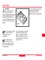
Product labelling:
This device complies with part 15 of the FCC Rules.
Operation is subject to the following two conditions:
(1) This device may not cause harmful interference, and
(2) this device must accept any interference received,
including interference that may cause undesired operation.
This device
contains a
Type: RCS1100
transmitter:
FCC ID:
Art.No.: .667173
HSW-2400M
Power: 12V/6V ---,
SSDL-1
0.4Amax; EPR:100mW
Leica Geosystems AG
CH-9435 Heerbrugg
Manufactured: 2002
Made in Switzerland S.No.: #$1#
If this equipment does cause harmful interference to
radio or television reception, which can be determined by
turning the equipment off and on, the user is encouraged
to try to correct the interference by one or more of the
following measures:
• Reorient or relocate the receiving antenna.
• Increase the separation between the equipment and
receiver.
• Connect the equipment into an outlet on a circuit different from that to which the receiver is connected.
• Consult the dealer or an experienced radio/TV
technician for help.
Safety directions
!
This device complies with
part 15 of the FCC Rules.
Operation is subject to
the following two
conditions: (1) This
device may not cause
harmful interference, and
(2) this device must
accept any interference
received, including
interference that may
cause undesired
operation.
Tcs11z03
5
FCC statement (applicable in U.S.)
40
RCS1100-1.2.0en
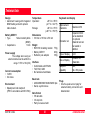
Technical data
Design
• Aluminium housing with integrated
NiMH battery and with optional
radio modem.
Battery GEB111
• Type
Nickel metal hydride
(NiMH)
• Capacitance
1.8Ah
Power supply
The voltage when using an
external cable must be within the
range 11.5V to 14V (DC)
Current consumption
• 12/6V=
• 0.4 Amax
Environment
• Splashproof and dustproof
(IP53 in accordance with IEC 529)
RCS1100-1.2.0de
Temperature
Operation:
Storage:
Keyboard and display
-20°C to +50°C
(-4°F to +122°F)
-40°C to +70°C
(-40°F to +158°F)
Dimensions
• 160 mm x 135 mm x 50 mm
Weight
• RCS1100 including modem 770g
• Battery GEB111
200g
• Reflector pole adapter
180g
Interface
• Conformable with RS232
• TxD, RxD, GND
• No hardware handshake
Baud rate
• 2400/4800/9600/19200/34800 bps
• Serial, asynchronous
Data format
• 7/8 data bits
• 1/2 stop bits
• Parity none/even/odd
41
Alphanumeric
characters
Maximum 256
Character set
Expandet ASCII
set as standard.
An optional
character set can
be loaded in
addition
Type of display
LCD
Size of display
8 rows of 32
characters
Graphics
capability
Yes,
64 x 256 pixels
Plugs
• One five-pole Lemo-0 plug for
external battery connection and
data transfer
Technische Daten
6
7
8
15
17
26
28
5
7
6
Radio modem
Conformity to national regulations
• FCC part 15 (applicable in U.S.)
• European directive 1999/5/EC on
radio equipment and
telecommunications terminal
equipment (see CE Conformity
Declaration).
Frequency range
Limited to 2446.5 - 2483.5
MHz
Transmission power
< 100 mW (e.r.p.)
Antenna
• λ/2 -360° with SMA connector.
• The conformity for countries with
other national regulations not
covered by FCC part 15 or
European directives 1999/5/EC
has to be approved prior to use
and operation.
8
Technische Daten
42
RCS1100-1.2.0de
Index
A
Absolute angle values
Alignment of the TPS1100
Allocation of keys
Antenna extension
22
18
17
B
Battery
Battery status
13, 31
25
C
Chargers
Compass
14
17, 20
D
Dust
30
E
External modem
28
I
Illumination
25
J
Joystick
Joystick mode
22
17
L
Language
26
P
Packaging
Plugs
PowerSearch
13
30
21
RCS1100-1.2.0de
R
S
Radio link
Reflector-pole adapter
Relative angle values
25
9
22
Serial interface
Software
Software Info
27
16
29
T
Temperature
Transport
Trouble
W
Working area
30
13, 30
12
19
6
7
8
15
17
26
28
43
Stichwortverzeichnis
Leica Geosystems AG, Heerbrugg, Switzerland, has been certified as being equipped
with a quality system which meets the
International Standards of Quality Management and Quality Systems (ISO standard
9001) and Environmental Management
Systems (ISO standard 14001).
710526-1.2.0en
Printed in Switzerland - Copyright Leica
Geosystems AG, Heerbrugg, Switzerland 2002
Translation of original text (710525-1.2.0de)
Total Quality ManagementOur commitment to total customer
satisfaction
Ask your local Leica Geosystems agent for more
information about our TQM program.
Leica Geosystems AG
CH-9435 Heerbrugg
(Switzerland)
Phone +41 71 727 31 31
Fax +41 71 727 46 73
www.leica-geosystems.com
Stichwortverzeichnis