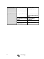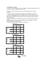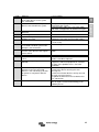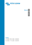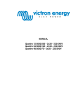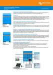
1
EN Manual Appendix MultiPlus 12 | 3000 | 120 – 50 | 120V 24 | 3000 | 70 – 50 | 120V Copyrights 2007 Victron Energy B.V. All Rights Reserved This publication or parts thereof may not be reproduced in any form, by any method, for any purpose. For conditions of use and permission to use this manual for publication in other than the English language, contact Victron Energy B.V. VICTRON ENERGY B.V. MAKES NO WARRANTY, EITHER EXPRESSED OR IMPLIED, INCLUDING BUT NOT LIMITED TO ANY IMPLIED WARRANTIES OF MERCHANTABILITY OR FITNESS FOR A PARTICULAR PURPOSE, REGARDING THESE VICTRON ENERGY PRODUCTS AND MAKES SUCH VICTRON ENERGY PRODUCTS AVAILABLE SOLELY ON AN “AS IS” BASIS. IN NO EVENT SHALL VICTRON ENERGY B.V. BE LIABLE TO ANYONE FOR SPECIAL, COLLATERAL, INCIDENTAL, OR CONSEQUENTIAL DAMAGES IN CONNECTION WITH OR ARISING OUT OF PURCHASE OR USE OF THESE VICTRON ENERGY PRODUCTS. THE SOLE AND EXCLUSIVE LIABILITY TO VICTRON ENERGY B.V., REGARDLESS OF THE FORM OF ACTION, SHALL NOT EXCEED THE PURCHASE PRICE OF THE VICTRON ENERGY PRODUCTS DESCRIBED HERE IN. Victron Energy B.V. reserves the right to revise and improve its products as it sees fit. This publication describes the state of this product at the time of its publication and may not reflect the product at all times in the future EN 1. SAFETY INSTRUCTIONS In general Appendix Please read the documentation supplied with this product first, so that you are familiar with the safety signs en directions before using the product. This product is designed and tested in accordance with international standards. The equipment should be used for the designated application only. WARNING: DANGER OF ELECTRICAL SHOCK The product is used in combination with a permanent energy source (battery). Even if the equipment is switched off, a dangerous electrical voltage can occur at the input and/or output terminals. Always switch the AC power off and disconnect the battery before performing maintenance. The product contains no internal user-serviceable parts. Do not remove the front panel and do not put the product into operation unless all panels are fitted. All maintenance should be performed by qualified personnel. Never use the product at sites where gas or dust explosions could occur. Refer to the specifications provided by the manufacturer of the battery to ensure that the battery is suitable for use with this product. The battery manufacturer's safety instructions should always be observed. WARNING: do not lift heavy objects unassisted. Installation Read the installation instructions before commencing installation activities. This product is a safety class I device (supplied with a ground terminal for safety purposes). Its AC input and/or output terminals must be provided with uninterruptible grounding for safety purposes. An additional grounding point is located on the outside of the product. If it can be assumed that the grounding protection is damaged, the product should be taken out of operation and prevented from accidentally being put into operation again; contact qualified maintenance personnel. Ensure that the connection cables are provided with fuses and circuit breakers. Never replace a protective device by a component of a different type. Refer to the manual for the correct part. Check before switching the device on whether the available voltage source conforms to the configuration settings of the product as described in the manual. Ensure that the equipment is used under the correct operating conditions. Never operate it in a wet or dusty environment. Ensure that there is always sufficient free space around the product for ventilation, and that ventilation openings are not blocked. 1 Install the product in a heatproof environment. Ensure therefore that there are no chemicals, plastic parts, curtains or other textiles, etc. in the immediate vicinity of the equipment. Transport and storage On storage or transport of the product, ensure that the mains supply and battery leads are disconnected. No liability can be accepted for damage in transit if the equipment is not transported in its original packaging. Store the product in a dry environment; the storage temperature should range from – 20°C to 60°C. Refer to the battery manufacturer's manual for information on transport, storage, charging, recharging and disposal of the battery. 2 EN 2. DESCRIPTION 2.1 In general Appendix The basis of the MultiPlus is an extremely powerful sine inverter, battery charger and automatic switch in a compact casing. The MultiPlus features the following additional, often unique characteristics: Automatic and uninterruptible switching In the event of a supply failure or when the generating set is switched off, the MultiPlus will switch over to inverter operation and take over the supply of the connected devices. This is done so quickly that operation of computers and other electronic devices is not disturbed (Uninterruptible Power Supply or UPS functionality). This makes the MultiPlus highly suitable as an emergency power system in industrial and telecommunication applications. Virtually unlimited power thanks to parallel operation Up to 6 MultiPlus units can operate in parallel. Six units 24/3000/70, for example, will provide 15kW / 18kVA output power and 420 Amps charging capacity. Three phase and split phase capability Three units can be configured for three-phase or split phase output. But that’s not all: up to 6 sets of three units can be parallel connected to provide 45kW / 54kVA inverter power and more than 1000A charging capacity. Split phase options Two units can be stacked to provide 120-0-120V, and additional units can be paralleled up to a total of 6 units per phase, to supply up to 30kW / 36kVA of split phase power. Alternatively, a split phase AC source can be obtained by connecting our autotransformer (see data sheet on www.victronenergy.com) to an ‘European’ inverter programmed to supply 240V / 60Hz. PowerControl – maximum use of limited shore current The MultiPlus can supply a huge charging current. This implies heavy loading of the shore connection or generator set. Therefore a maximum current can be set. The MultiPlus then takes other power users into account, and only uses 'surplus' current for charging purposes. PowerAssist – Extended use of your generator and shore current: the MultiPlus “co-supply” feature This feature takes the principle of PowerControl to a further dimension allowing the MultiPlus to supplement the capacity of the alternative source. Where peak power is so often required only for a limited period, the MultiPlus will make sure that insufficient shore or generator power is immediately compensated for by power from the battery. When the load reduces, the spare power is used to recharge the battery. This unique feature offers a definitive solution for the ‘shore current problem’: electric tools, dish washers, washing machines, electric cooking etc. can all run on 16A shore current, or even less. In addition, a smaller generator can be installed. 3 Programmable relay The MultiPlus is equipped with a multi-functional relay that by default is programmed as an alarm relay. The relay can be programmed for all kinds of other applications however, for example to start a generator. Programmable with DIP switches, VE.Net panel or personal computer The MultiPlus is supplied ready for use. Three features are available for changing certain settings if desired: - The most important settings (including parallel operation of up to three devices and 3-phase operation) can be changed in a very simple manner, using DIP switches. - All settings, with exception of the multi-functional relay, can be changed with a VE.Net panel. - All settings can be changed with a PC and free of charge software, downloadable from our website www.victronenergy.com 2.2 Battery charger Adaptive 4-stage charge characteristic: bulk – absorption – float – storage The MultiPlus features a microprocessor controlled ‘adaptive’ battery management system that can be preset to suit different types of batteries. The ‘adaptive’ feature will automatically optimise the process relative to the way the battery is being used. The right amount of charge: variable absorption time When only shallow discharges occur (a yacht connected to shore power for example) the absorption time is kept short in order to prevent overcharging of the battery. After a deep discharge the absorption time is automatically increased to make sure that the battery is completely recharged. Preventing damage due to excessive gassing: the BatterySafe mode If, in order to quickly charge a battery, a high charge current in combination with a high absorption voltage has been chosen, the MultiPlus will prevent damage due to excessive gassing by automatically limiting the rate of voltage increase once the gassing voltage has been reached Less maintenance and aging when the battery is not in use: the Storage mode The storage mode kicks in whenever the battery has not been subjected to discharge during 24 hours. In the storage mode float voltage is reduced to 2,2V/cell (13,2V for 12V battery) to minimise gassing and corrosion of the positive plates. Once a week the voltage is raised back to the absorption level to ‘equalize’ the battery. This feature prevents stratification of the electrolyte and sulphation, a major cause of early battery failure. 4 EN Two outputs to charge 2 battery banks The MultiPlus features two outputs, of which one can carry the full output current. The second output, limited to approximately 4 A and with a slightly lower output voltage, is intended to top up a starter battery. Appendix To increase battery life: temperature compensation Every MultiPlus comes with a battery temperature sensor. When connected, charge voltage will automatically decrease with increasing battery temperature. This feature is especially recommended for sealed batteries and/or when important fluctuations of battery temperature are expected. Battery voltage sense In order to compensate for voltage loss due to cable resistance the MultiPlus is provided with a voltage sense facility so that the battery always receives the correct charge voltage. Learn more about batteries and battery charging To learn more about batteries and charging batteries, please refer to our book ‘Energy Unlimited’ (available free of charge from Victron Energy and downloadable from www.victronenergy.com). For more information about adaptive charging please look under Technical Information on our website. 5 3. OPERATION 3.1 On/Off/Charger Only Switch When switched to "on", the product is fully functional. The inverter will come into operation and the LED "inverter on" will light up. An AC voltage connected to the "AC in" terminal will be switched through to the "AC out" terminal, if within specifications. The inverter will switch off, the "mains on" LED will light up and the charger commences charging. The "bulk", "absorption" or "float" LEDs will light up, depending on the charger mode. If the voltage at the "AC-in" terminal is not within specifications, the inverter will switch on. When the switch is switched to "charger only", only the battery charger of the MultiPlus will operate (if mains voltage is present). In this mode input voltage also is switched through to the "AC out" terminal. NOTE: When only the charger function is required, ensure that the switch is switched to "charger only". This prevents the inverter from being switched on if the mains voltage is lost, thus preventing your batteries from running flat. 3.2 Remote control Remote control is possible with a 3-way switch or with a Phoenix Multi Control panel. The Phoenix Multi Control panel has a simple rotary knob with which the maximum current of the AC input can be set: see PowerControl and PowerAssist in Section 2. 3.3 Equalisation and forced absorption 3.3.1 Equalisation Traction batteries may require regular equalisation charging. In the equalisation mode, the MultiPlus will charge with increased voltage for one hour (1V above the absorption voltage for a 12V battery, 2V for a 24V battery). The charging current is then limited to 1/4 of the set value. The “bulk” and “absorption” LEDs flash intermittently. Equalisation mode supplies a higher charging voltage than most DC consuming devices can cope with. These devices must be disconnected before additional charging takes place. 3.3.2 Forced absorption Under certain circumstances, it can be desirable to charge the battery for a fixed time at absorption voltage level. In Forced Absorption mode, the MultiPlus will charge at the normal absorption voltage level during the set maximum absorption time. The “absorption” LED lights. 6 EN 3.3.3 Activating equalisation or forced absorption The MultiPlus can be put into both these states from the remote panel as well as with the front panel switch, provided that all switches (front, remote and panel) are set to “on” and no switches are set to “charger only”. In order to put the MultiPlus in this state, the procedure below should be followed. NOTE: Switching from “on” to “charger only” and back, as described below, must be done quickly. The switch must be toggled such that the intermediate position is 'skipped', as it were. If the switch remains in the “off” position even for a short time, the device may be turned off. In that case, the procedure must be restarted at step 1. A certain degree of familiarisation is required when using the front switch. When using the remote panel, this is less critical. Procedure: 1. Check whether all switches (i.e. front switch, remote switch or remote panel switch if present) are in the “on” position. 2. Activating equalisation or forced absorption is only meaningful if the normal charging cycle is completed (charger is in 'Float'). 3. To activate: a. Switch rapidly from “on” to “charger only” and leave the switch in this position for ½ to 2 seconds. b. Switch rapidly back from “charger only” to “on” and leave the switch in this position for ½ to 2 seconds. c. Switch once more rapidly from “on” to “charger only” and leave the switch in this position. 4. On the MultiPlus (and, if connected, on the MultiControl panel) the three LEDs “Bulk”, “Absorption” and “Float” will now flash 5 times. 5. Subsequently, the LEDs “Bulk”, “Absorption” and “Float” will each light during 2 seconds. a. If the switch is set to “on” while the “Bulk” LED lights, the charger will switch to equalisation. b. If the switch is set to “on” while the “Absorption” LED lights, the charger will switch to forced absorption. c. If the switch is set to “on” after the three LED sequence has finished, the charger will switch to “Float”. d. If the switch is has not been moved, the MultiPlus will remain in ‘charger only’ mode and switch to “Float”. 7 Appendix If the switch is not in the required position after following this procedure, it can be switched over quickly once. This will not change the charging state. 3.4 LED Indications LED off LED flashes LED illuminated Inverter Charger mains on inverter on Bulk inverter on overload off Absorption Float low battery charger only Charger mains on temperature inverter on Bulk inverter on overload off absorption Float low battery charger only Charger mains on temperature on inverter on overload off absorption 8 The nominal output of the inverter is exceeded. The “overload” LED flashes inverter Bulk Float The inverter is on and supplies power to the load. low battery charger only temperature The inverter is switched off due to overload or short circuit. mains on inverter on inverter on overload off absorption Float temperature inverter on Bulk inverter on overload off absorption Float temperature inverter on Bulk inverter on overload off absorption Float temperature inverter on Bulk inverter on overload off absorption Float The internal temperature is reaching a critical level. low battery charger only Charger mains on The battery is almost fully exhausted. low battery charger only Charger mains on The inverter has switched off due to low battery voltage. low battery charger only Charger mains on Appendix Bulk EN Charger low battery charger only The inverter has switched off due to the electronics temperature being too high. temperature 9 Charger mains on inverter on Bulk inverter on overload off absorption Float low battery charger only Charger mains on temperature inverter on Bulk inverter on overload off absorption Float -If the LEDs are flashing alternately, the battery is nearly exhausted and the nominal output is exceeded. -If "overload" and "low battery" flash simultaneously, the ripple voltage on the battery terminals is too high. low battery charger only The inverter switched off due to excess ripple voltage on the battery terminals. temperature Battery Charger Charger mains on inverter on Bulk inverter on overload off absorption Float low battery charger only Charger mains on temperature inverter on Bulk inverter on overload off absorption Float 10 The AC input voltage is switched through and the charger operates in bulk mode. low battery charger only temperature The mains voltage is switched through and the charger is on. The set absorption voltage, however, has not yet been reached. (BatterySafe mode) mains on inverter on inverter on overload off absorption low battery charger only Charger mains on temperature inverter on Bulk inverter on overload off absorption Float low battery charger only Charger mains on temperature on inverter on overload off Float The mains voltage is switched through and the charger operates in float mode. inverter Bulk absorption The mains voltage is switched through and the charger operates in absorption mode. charger only The mains voltage is switched through and the charger operates in equalize mode. low battery temperature 11 Appendix Bulk Float EN Charger Special Indications PowerControl charger mains on inverter on bulk inverter on overload off absorption float low battery charger only The AC input is switched through. The AC output current is equal to the preset maximum input current. The charge current is reduced to 0. temperature Power Assist charger mains on inverter on bulk inverter on overload off absorption float 12 low battery charger only temperature The AC input is switched through but the load requires more current than the preset maximum input current. The inverter is switched on to supply the required additional current. EN 4. Installation This product may only be installed by a qualified electrical engineer. The product must be installed in a dry and well-ventilated area, as close as possible to the batteries. There should be a clear space of at least 10 cm (4 inch) around the appliance for cooling. Excessively high ambient temperature will result in the following: Reduced service life. Reduced charging current. Reduced peak capacity, or shutdown of the inverter. Never position the appliance directly above the batteries. The MultiPlus is suitable for wall mounting. For mounting purposes, a hook and two holes are provided at the back of the casing (see appendix G). The device can be fitted either horizontally or vertically. For optimal cooling, vertical fitting is preferred. The interior of the product must remain accessible after installation. Try and keep the distance between the product and the battery to a minimum in order to minimize cable voltage losses. For safety purposes, this product should be installed in a heat-resistant environment. You should prevent the presence of e.g. chemicals, synthetic components, curtains or other textiles, etc., in the immediate vicinity. 13 Appendix 4.2 Location 4.2 Connection of battery cables In order to utilize the full capacity of the product, batteries with sufficient capacity and battery cables with sufficient cross section should be used. See table. Recommended battery capacity (Ah) Recommended DC fuse 12/3000/120 400–1200 400A 24/3000/70 200–700 300A 48/3000/35 100–400 125A 2x 50 mm2 2x 70 mm2 50 mm2 2x 50 mm2 35 mm2 2x 35 mm2 Recommended cross section (mm2) per + and - connection terminal 0–5m 5 – 10 m * ‘2x’ means two positive and two negative cables. Remark: Internal resistance is the important factor when working with low capacity batteries. Please consult your supplier or the relevant sections of our book “Energy Unlimited”, downloadable from our website. Procedure Proceed as follows to connect the battery cables: Use an insulated box spanner in order to avoid shorting the battery. Avoid shorting the battery cables. - Undo the four screws at the front of the enclosure and remove the front panel. - Connect the battery cables: see Appendix A. - Tighten the nuts well for minimal contact resistance. 14 4.3 Connection of the AC cabling EN Appendix The MultiPlus is a safety class I product (supplied with a ground terminal for safety purposes). Its AC input and/or output terminals and/or grounding point on the outside of the product must be provided with an uninterruptible grounding point for safety purposes. The MultiPlus is provided with a ground relay (relay H, see appendix B) that automatically connects the Neutral output to the chassis if no external AC supply is available. If an external AC supply is provided, the ground relay H will open before the input safety relay closes. This ensures the correct operation of an earth leakage circuit breaker that is connected to the output. In a fixed installation, an uninterruptable grounding can be secured by means of the grounding wire of the AC input. Otherwise the casing must be grounded. In a mobile installation (for example, with a shore current plug), interrupting the shore connection will simultaneously disconnect the grounding connection. In that case, the casing must be connected to the chassis (of the vehicle) or to the hull or grounding plate (of the boat). In case of a boat, direct connection to the shore ground is not recommended because of potential galvanic corrosion. The solution to this is using an isolation transformer. The terminal blocks can be found on the printed circuit board, see appendix A. The shore or mains cable must be connected to the MultiPlus with the aid of a three-wire cable. - The AC input cable can be connected to the terminal block “AC–in”. The AC input must be protected by a fuse or magnetic circuit breaker rated at 50A or less, and cable cross-section must be sized accordingly. If the input AC supply is rated at a lower value, the fuse or magnetic circuit breaker should be down sized accordingly. - The AC output cable can be connected directly to the terminal block "AC-out". With its PowerAssist feature the MultiPlus can add up to 5kVA (that is 3000 / 120 = 25A) to the output during periods of peak power requirement. Together with a maximum input current of 50A this means that the output can supply up to 50 + 25 = 75A. An earth leakage circuit breaker and a fuse or circuit breaker rated to support the expected load must be included in series with the output, and cable crosssection must be sized accordingly. The maximum rating of the fuse or circuit breaker is 75A. 15 4.4 Optional Connections A number of optional connections are possible(see appendix A) 4.4.1 Second Battery The MultiPlus has a connection for charging a starter battery. 4.4.2 Voltage Sense Two sense wires may be connected to compensate possible battery cable losses during charging. Use wires of at least 0.75mm2. 4.4.3 Temperature Sensor The temperature sensor supplied with the product may be used for temperaturecompensated charging. The sensor is isolated and must be mounted on the battery’s minus pole. 4.4.4 Remote Control The product can be remotely controlled in two ways. With an external switch. Operates only if the switch on the MultiPlus is set to “on”. With a Multi Control panel (connected to one of the two RJ48 sockets). Operates only if the switch on the MultiPlus is set to “on”. Only one remote control can be connected, i.e. either a switch or a remote control panel. 4.4.5. Programmable relay The MultiPlus is equipped with a multi-functional relay that by default is programmed as an alarm relay. The relay can be programmed for all kinds of other applications however, for example to start a generator (VEConfigure software needed). 16 EN 4.4.6 Parallel Connection The MultiPlus can be connected in parallel with several identical devices. To this end, a connection is established between the devices by means of standard RJ45 UTP cables. The system (one or more MultiPlus units plus optional control panel) will require subsequent configuration (see Section 5). In the event of connecting MultiPlus units in parallel, the following requirements must be met: 4.4.7 Three-phase operation The MultiPlus can also be used in 3-phase configuration. To this end, a connection between the devices is made by means of standard RJ45 UTP cables (the same as for parallel operation). The system (MultiPlus units plus an optional control panel) will require subsequently configuration (see Section 5). Pre-requisites: see Section 4.4.6. 4.4.8 Two phase (split phase) configuration (see appendix C) MultiPlus units can also be used in split phase configuration. To this end, a connection between the devices is made by means of standard RJ45 UTP cables (the same as for parallel operation). The system (MultiPlus units plus an optional control panel) will require subsequent configuration (see Section 5). Pre-requisites: see Section 4.4.6. 17 Appendix - A maximum of six units connected in parallel. - Only identical devices may be connected in parallel. - The DC connection cables to the devices must be of equal length and cross-section. If a positive and a negative DC distribution point is used, the cross-section of the connection between the batteries and the DC distribution point must at least equal the sum of the required cross-sections of the connections between the distribution point and the MultiPlus units. - Place the MultiPlus units close to each other, but allow at least 10 cm / 4 inch for ventilation purposes under, above and beside the units. - UTP cables must be connected directly from one unit to the other (and to the remote panel). Connection/splitter boxes are not permitted. - A battery-temperature sensor need only be connected to one unit in the system. If the temperature of several batteries is to be measured, you can also connect the sensors of other MultiPlus units in the system (with a maximum of one sensor per MultiPlus). Temperature compensation during battery charging responds to the sensor indicating the highest temperature. - Voltage sensing must be connected to the master (see Section 5.5.1.4). - If more than three units are connected in parallel in one system, a dongle is required (see Section 5). - Only one remote control (panel or switch) can be connected to the system. 5. Configuration Settings may only be changed by a qualified electrical engineer. Read the instructions thoroughly before implementing changes. During setting of the charger, the AC input must be removed. 5.1 Standard settings: ready for use On delivery, the MultiPlus is set to standard factory values. In general, these settings are suitable for single-unit operation. Warning: Possibly, the standard battery charging voltage is not suitable for your batteries! Refer to the manufacturer's documentation, or to your battery supplier! Standard MultiPlus factory settings Inverter frequency Input frequency range Input voltage range Inverter voltage Stand-alone / parallel / 3-phase AES (Automatic Economy Switch) Ground relay Charger on/ off Battery charge curve Charging current Battery type Automatic equalisation charging Absorption voltage Absorption time Float voltage Storage voltage Repeated absorption time Absorption repeat interval Bulk protection AC input current limit UPS feature Dynamic current limiter WeakAC BoostFactor Multi-functional relay VirtualSwitch PowerAssist 18 60 Hz 45 - 65 Hz 94 - 143 VAC 120 VAC stand-alone off on on Four-stage adaptive with BatterySafe mode 75% of the maximum charging current Victron Gel Deep Discharge (also suitable for Victron AGM deep discharge off 14.4 / 28.8 / 57.6 V up to 8 hours (depending on bulk time) 13.8 / 27.6 / 55.2 V 13.2 / 26.4 / 52.8V (not adjustable) 1 hour 7 days on 50A (= adjustable current limit for PowerControl and PowerAssist functions) on off off 2 alarm function controls the multi-functional relay on 5.2 Explanation of settings EN Appendix Settings that are not self-explanatory are described briefly below. For further information, please refer to the help files in the software configuration programs (see Section 5.3). Inverter frequency Output frequency if no AC is present at the input. Adjustability: 50Hz; 60Hz Input frequency range Input frequency range accepted by the MultiPlus. The MultiPlus synchronises within this range with the AC input frequency. The output frequency is then equal to the input frequency. Adjustability: 45 – 65 Hz; 45 – 55 Hz; 55 – 65 Hz Input voltage range Voltage range accepted by the MultiPlus. The MultiPlus synchronises within this range with the AC input voltage. The output voltage is then equal to the input voltage. Adjustability: Lower limit: 94 - 120V Upper limit: 120 - 143V Inverter voltage Output voltage of the MultiPlus in battery operation. Adjustability: 95 – 128V Stand-alone / parallel operation / 2-3 phase setting Using several devices, it is possible to: - increase total inverter power (several devices in parallel) - create a split-phase system - create a 3-phase system. The standard product settings are for standalone operation. For parallel, three phase or split phase operation see section 4.6.6 and 4.6.7. AES (Automatic Economy Switch) If this setting is turned ‘on’, the power consumption in no-load operation and with low loads is decreased by approx. 20%, by slightly 'narrowing' the sinusoidal voltage. Adjustable with DIP switches. Applicable in stand-alone configuration only. 19 Search Mode Instead of the AES mode, the search mode can also be chosen (with help of VEConfigure only). If search mode is ‘on’, the power consumption in no-load operation is decreased by approx. 70%. In this mode the MultiPlus, when operating in inverter mode, is switched off in case of no load or very low load, and switches on every two seconds for a short period. If the output current exceeds a set level, the inverter will continue to operate. If not, the inverter will shut down again. The Search Mode “shut down” and “remain on” load levels can be set with VEConfigure. The factory settings are: Shut down: 40 Watt (linear load) Turn on: 100 Watt (linear load) Not adjustable with DIP switches. Applicable in stand-alone configuration only. Ground relay (see appendix B) With this relay (H), the neutral conductor of the AC output is grounded to the chassis when the back feed safety relay is open. This ensures the correct operation of earth leakage circuit breakers in the output. In case a non-grounded output is required during inverter operation, this function can be turned off with help of VEConfigure. Not adjustable with DIP switches. Battery charge curve The standard setting is ‘Four-stage adaptive with BatterySafe mode’. See Section 2 for a description. This is the recommended charge curve. See the help files in the software configuration programs for other features. Alternatively, ‘Fixed’ mode can be selected with DIP switches. Battery type The standard setting is the most suitable for Victron Gel Deep Discharge, Gel Exide A200, and tubular plate stationary batteries (OPzS). This setting can also be used for many other batteries: e.g. Victron AGM Deep Discharge and other AGM batteries, and many types of flooded flat-plate lead-acid batteries. Four charging voltages can be set with DIP switches. Absorption time The absortion time depends on the bulk time (adaptive charge curve), so that the battery is optimally charged. If the ‘fixed’ charging characteristic is selected, the absorption time is fixed. For most batteries, a maximum absorption time of eight hours is suitable. If an extra high absorption voltage is selected for rapid charging (only possible for open, flooded batteries!), four hours is preferable. With DIP switches, a time of eight or four hours can be set. For the adaptive charge curve, this determines the maximum absorption time. 20 EN Storage voltage, Repeated Absorption Time, Absorption Repeat Interval See Section 2. Not adjustable with DIP switches. Appendix Bulk Protection When this setting is ‘on’, the bulk charging time is limited to 10 hours. A longer charging time could indicate a system error (e.g. a battery cell short-circuit). Not adjustable with DIP switches. AC input current limit These are the current limit settings at which PowerControl and PowerAssist come into operation. The factory setting is 50A. See Section 2, the book 'Energy Unlimited', or the many descriptions of this unique feature on our website www.victronenergy.com . Remark: lowest allowable current setting for PowerAssist: 11A. (11A per unit in case of parallel operation) UPS feature If this setting is ‘on’ and AC on the input fails, the MultiPlus switches to inverter operation practically without interruption. The MultiPlus can therefore be used as an Uninterruptible Power Supply (UPS) for sensitive equipment such as computers or communication systems. The output voltage of some small generator sets is too unstable and distorted for using this setting* – the MultiPlus would continually switch to inverter operation. For this reason, the setting can be turned off. The MultiPlus will then respond less quickly to AC input voltage deviations. The switchover time to inverter operation is consequently slightly longer, but most equipment (most computers, clocks or household equipment) is not adversely impacted. Recommendation: Turn the UPS feature off if the MultiPlus fails to synchronise, or continually switches back to inverter operation. *In general, the UPS setting can be left ‘on’ if the MultiPlus is connected to a generator with a ‘synchronous AVR regulated alternator’. The UPS mode may have to be set to ‘off’ if the MultiPlus is connected to a generator with a ‘synchronous capacitor regulated alternator’ or an asynchronous alternator. Dynamic current limiter Intended for generators, the AC voltage being generated by means of a static inverter (so-called ‘inverter’ generators). In these generators, rpm is down-controlled if the load is low: this reduces noise, fuel consumption and pollution. A disadvantage is that the output voltage will drop severely or even completely fail in the event of a sudden load increase. More load can only be supplied after the engine is up to speed. If this setting is ‘on’, the MultiPlus will start supplying extra power at a low generator output level and gradually allow the generator to supply more, until the set current limit is reached. This allows the generator engine to get up to speed. This setting is also often used for ‘classic’ generators that respond slowly to sudden load variation. 21 WeakAC Strong distortion of the input voltage can result in the charger hardly operating or not operating at all. If WeakAC is set, the charger will also accept a strongly distorted voltage, at the cost of greater distortion of the input current. Recommendation: Turn WeakAC on if the charger is hardly charging or not charging at all (which is quite rare!). Also turn on the dynamic current limiter simultaneously, and reduce the maximum charging current to prevent overloading the generator if necessary. Not adjustable with DIP switches. BoostFactor Change this setting only after consulting with Victron Energy or with an engineer trained by Victron Energy! Not adjustable with DIP switches. Multi-functional relay By default, the multi-functional relay is set as an alarm relay, i.e. the relay will deenergise in the event of an alarm or a pre-alarm (inverter almost too hot, ripple on the input almost too high, battery voltage almost too low). Not adjustable with DIP switches. VirtualSwitch The VirtualSwitch is a software function in the MultiPlus microprocessor. The inputs of this function are parameters that can be selected with VEConfigure (e.g. certain alarms or voltage levels). The output is binary (0 or 1). The output can be connected to a binary microprocessor output (e.g. the multi-functional relay, or the relay in the AC input). If connected to the multi-functional relay, and with battery voltage and time as input values, for example, the VirtualSwitch can be configured to supply a generator starting signal. If connected to an AC input relay, and with battery voltage and time as input, for example, the connected mains supply can be interrupted. Application: A house or an office connected to the public mains, fitted with solar panels with energy storage in batteries. The batteries are used to prevent return delivery to the mains. During the day, redundant solar energy is stored in batteries. This energy is used in the evenings and at night. An energy shortfall is compensated by the mains. The MultiPlus converts the battery DC voltage to AC. The power is always less than or equal to the power consumption, so that return delivery to the mains does not occur. In the event of mains failure, the MultiPlus isolates the premises from the mains, which become autonomous (self-sufficient). In this way, a solar energy installation or a combined micro-scale heating and power plant can be economically used in areas with an unreliable mains supply and/or financially unfavourable energy-return conditions. 22 5.3 Configuration by computer 5.3.1 VE.Bus Quick Configure Setup VE.Bus Quick Configure Setup is a software program with which systems with a maximum of three MultiPlus units (parallel or three phase operation) can be configured in a simple manner. VEConfigureII forms part of this program. The software free can be downloaded free of charge at www.victronenergy.com. For connection to the computer, a RJ45 UTP cable and the MK2.2b RS485-to-RS232 interface is required. If the computer has no RS232 connection, but does have USB, a RS232-to-USB interface cable is needed. Both are available from Victron Energy. 5.3.2 VE.Bus System Configurator and dongle For configuring advanced applications and/or systems with four or more MultiPlus units, VE.Bus System Configurator software must be used. The software can be downloaded free of charge at www.victronenergy.com . VEConfigureII forms part of this program. The system can be configured without a dongle, and will be fully functional during 15 minutes (as a demonstration facility). For permanent use, a dongle – available at additional charge – is required. For connection to the computer, a RJ45 UTP cable and the MK2.2b RS485-to-RS232 interface is required. If the computer has no RS232 connection, but does have USB, a RS232-to-USB interface cable is needed. Both are available from Victron Energy. 5.4 Configuration with a VE.Net panel To this end, a VE.Net panel and the VE.Net to VE.Bus converter is required. With VE.Net all parameters are accessible, with the exception of the multi-functional relay and the VirtualSwitch. 23 Appendix For changing settings with the computer, the following is required: • VEConfigureII software: can be downloaded free of charge at www.victronenergy.com. • A RJ45 UTP cable and the MK2.2b RS485-to-RS232 interface. If the computer has no RS232 connection, but does have USB, a RS232-to-USB interface cable is needed. Both are available from Victron Energy. EN All settings can be changed by means of a computer or with a VE.Net panel (except for the multi-functional relay and the VirtualSwitch when using VE.Net). The most common settings (including parallel and 3-phase operation) can be changed by means of DIP switches (see Section 5.5). 5.5 Configuration with DIP switches A number of settings can be changed using DIP switches (see appendix A, position M). This is done as follows: Turn the MultiPlus on, preferably without load en without AC voltage on the input. The MultiPlus will then operate in inverter mode. Step 1: Setting the DIP switches for: - the required current limitation of the AC input. - AES (Automatic Economy Switch) - maximum charge current. - selection of stand-alone, parallel or 3-phase operation. To store the settings after the required values have been set: press the 'Up' button for 2 seconds (upper button to the right of the DIP switches, see appendix A, position J). The DIP switches can now be used to apply the remaining settings (step 2). Step 2: other settings To store the settings after the required values have been set: press the 'Down' button for 2 seconds (lower button to the right of the DIP switches). The DIP switches can be left in the selected positions, so that the ’other settings’ can always be recovered. Remarks: - The DIP switch functions are described in 'top to bottom' order. Since the uppermost DIP switch has the highest number (8), descriptions start with the switch numbered 8. - In parallel mode or 3-phase mode, not all devices require all settings to be made (see section 5.5.1.4). For parallel or 3-phase mode, read the whole setting procedure and make a note of the required DIP switch settings before actually implementing them. 24 EN 5.5.1 Step 1 5.5.1.1 Current limitation AC input (default: 50A) If the current demand (MultiPlus load + battery charger) threatens to exceed the set AC input current, the MultiPlus will first reduce its charging current (PowerControl), and subsequently supply additional power from the battery (PowerAssist), if needed. Appendix The AC input current limit can be set to eight different values by means of DIP switches. With a Multi Control Panel, a variable current limit can be set for the AC input. Remark: With a VE.bus Control Panel or a Digital Control Panel and an external AC change-over switch two different limits can be set, for two AC sources, for example the mains/grid and a generator. Procedure The AC input current limit can be set using DIP switches ds8, ds7 and ds6 (default setting: 50A). Procedure: set the DIP switches to the required value: ds8 ds7 ds6 off off off = 15A (1.8kVA at 120V) off off on = 20A (2.4kVA at 120V) off on off = 25A (3.0kVA at 120V) off on on = 30A (3.6kVA at 120V) on off off = 35A (4.2kVA at 120V) on off on = 40A (4.8kVA at 120V) on on off = 50A (6.0kVA at 120V) on on on = not used Remark: Manufacturer-specified continuous power ratings for small generators are sometimes inclined to be rather optimistic. In that case, the current limit should be set to a much lower value than would otherwise be required on the basis of manufacturer-specified data. 5.5.1.2 AES (Automatic Economy Switch) Procedure: set ds5 to the required value: ds5 off = AES off on = AES on 25 5.5.1.3 Battery charge current limitation (default setting 75%) For maximum battery life, a charge current of 10% to 20% of the capacity in Ah should be applied. Example: optimal charge current of a 24V/500Ah battery bank: 50A to 100A. The temperature sensor supplied automatically adjusts the charging voltage to the battery temperature. If faster charging – and a subsequent higher current – is required: - The temperature sensor supplied should always be fitted, since fast charging can lead to a considerable temperature rise of the battery bank. The charging voltage will be adapted to the higher temperature (i.e. lowered) by means of the temperature sensor. - The bulk charge time will sometimes be so short that a fixed absorption time would be more satisfactory (‘fixed’ absorption time, see ds5, step 2). Procedure The battery charge current can be set in four steps, using DIP switches ds4 and ds3 (default setting: 75%). ds4 ds3 off off = 25% off on = 50% on off = 75% on on = 100% 26 27 Appendix The combination ds2=on and ds1=on is not used. EN 5.5.1.4 Stand-alone, parallel, 3-phase and split phase operation Using DIP switches ds2 and ds1, three system configurations can be selected. NOTE: - When configuring a parallel, 3-phase or split phase system, all related devices should be interconnected using RJ45 UTP cables (see appendix C, D). All devices must be turned on. They will subsequently return an error code (see Section 7), since they have been integrated into a system and still are configured as ‘standalone’. This error message can safely be ignored. - Storing settings (by pressing the ‘Up’ button (step 1) – and later on the ‘Down’ button (step 2) – for 2 seconds) should be done on one device only. This device is the ‘master’ in a parallel system or the ‘leader’ (L1) in a 3-phase or split phase system. In a parallel system, the step-1 setting of DIP switches ds8 to ds3 need to be done on the master only. The slaves will follow the master with regard to these settings (hence the master/slave relationship). In a 3-phase or split phase system, a number of settings are also required for the other devices, i.e. the followers (for phases L2 and L3). (The followers, therefore, do not follow the leader for all settings, hence the leader/follower terminology). - A change in the setting ‘stand-alone / parallel / 3-phase’ is only activated after the setting has been stored (by pressing the ‘UP’ button for 2 seconds) and after all devices have been turned off and then on again. In order to start up a VE.Bus system correctly, all devices should therefore be turned off after the settings have been stored. They can then be turned on in any order. The system will not start until all devices have been turned on. - Note that only identical devices can be integrated in one system. Any attempt to use different models in one system will fail. Such devices may possibly function correctly again only after individual reconfiguration for ‘stand-alone’ operation. DIP switches ds2 and ds1 are reserved for the selection of stand-alone, parallel or 3-phase operation Stand-alone operation Step 1: Setting ds2 and ds1 for stand-alone operation DS-8 AC input Set as desired DS-7 AC input Set as desired DS-6 AC input Set as desired DS-5 AES Set as desired DS-4 Charging current Set as desired DS-3 Charging current Set as desired DS-2 Stand-alone operation DS-1 Stand-alone operation off off Examples of the other DIP switch settings for stand-alone mode are given below. Example 1 shows the factory setting Note: since factory settings are entered by computer, all DIP switches of a new product are set to ‘off’ and do not reflect the actual settings in the microprocessor. Four examples of stand-alone settings: DS-8 AC input DS-7 AC input DS-6 AC input DS-5 AES DS-4 Ch. current DS-3 Ch. current DS-2 St.-alone mode DS-1 St.-alone mode on on off off on off off off Step1, stand-alone Example 1 (factory setting): 8, 7, 6 AC-in: 50A 5 AES: off 4, 3 Charging current: 75% 2, 1 Stand-alone mode DS-8 DS-7 DS-6 DS-5 DS-4 DS-3 DS-2 DS-1 on on off off on on off off Step1, stand-alone Example 2: 8, 7, 6 AC-in: 50A 5 AES: off 4, 3 Charge: 100% 2, 1 Stand-alone DS-8 DS-7 DS-6 DS-5 DS-4 DS-3 DS-2 DS-1 off on on off on on off off Step1, stand-alone Example 3: 8, 7, 6 AC-in: 30A 5 AES: off 4, 3 Charge: 100% 2, 1 Stand-alone DS-8 DS-7 DS-6 DS-5 DS-4 DS-3 DS-2 DS-1 on off on on off on Step1, stand-alone Example 4: 8, 7, 6 AC-in: 40A 5 AES: on 4, 3 Charge: 50% 2, 1 Stand-alone To store the settings after the required values have been set: press the 'Up' button for 2 seconds (upper button to the right of the DIP switches, see appendix A, position J). The overload and lowbattery LED’s will flash to indicate acceptance of the settings. We recommend making a note of the settings, and filing this information in a safe place. You can now re-use the DIP switches to apply the remaining settings (step 2). 28 off off Master Slave 1 Set Set Set na Set Set off on DS-8 na DS-7 na DS-6 na DS-5 na DS-4 na DS-3 na DS-2 Slave 1 DS-1 Slave 1 Slave 2 (optional) off off DS-8 na DS-7 na DS-6 na DS-5 na DS-4 na DS-3 na DS-2 Slave 2 DS-1 Slave 2 Appendix DS-8 AC input DS-7 AC input DS-6 AC input DS-5 AES DS-4 Ch. current DS-3 Ch. current DS-2 Master DS-1 Master EN Parallel operation (appendix C) Step 1: Setting ds2 and ds1 for parallel operation off on The current settings (AC current limitation and charging current) are multiplied by the number of devices. However, the AC current limitation setting when using a remote panel will always correspond to the value indicated on the panel and is not multiplied by the number of devices. Example: 9kVA parallel system - If an AC input current limit of 20A is set on the master and the system consists of three devices, then the effective system current limit will be equal to 3 x 20 = 60A. - If a 30A panel is connected to the master, the system current limit is adjustable to a maximum of 30A, regardless of the number of devices. - If the charging current on the master is set to 100% (70A for a MultiPlus 24/3000/70) and the system consists of three devices, then the effective system charging current is equal to 3 x 70 = 210A. The settings according to this example (9kVA parallel system with 30A Multi Control Panel) are as follows: 29 Master DS-8 na (30A panel) DS-7 na (30A panel) DS-6 na (30A panel) DS-5 AES na DS-4 Ch. current 3x70A DS-3 Ch. current 3x70A DS-2 Master DS-1 Master Slave 1 on on off on DS-8 na DS-7 na DS-6 na DS-5 na DS-4 na DS-3 na DS-2 Slave 1 DS-1 Slave 1 Slave 2 off off DS-8 na DS-7 na DS-6 na DS-5 na DS-4 na DS-3 na DS-2 Slave 2 DS-1 Slave 2 off on To store the settings after the required values have been set: press the 'Up' button of the master for 2 seconds (upper button to the right of the DIP switches, see appendix A, position J). The overload and low-battery LED’s will flash to indicate acceptance of the settings. We recommend making a note of the settings, and filing this information in a safe place. You can now re-use the DIP switches to apply the remaining settings (step 2). 30 Leader (L1) Follower (L2) Set Set Set na Set Set DS-8 Set DS-7 Set DS-6 Set DS-5 na DS-4 na DS-3 na DS-2 Follower 1 DS-1 Follower 1 on off Follower (L3) DS-8 Set DS-7 Set DS-6 Set DS-5 na DS-4 na DS-3 na DS-2 Follower 2 DS-1 Follower 2 off off Appendix DS-8 AC input DS-7 AC input DS-6 AC input DS-5 AES DS-4 Ch. current DS-3 Ch. current DS-2 Leader DS-1 Leader EN Three phase operation (appendix D) Step 1: Setting ds2 and ds1 for 3-phase operation off on As the table above shows, the AC-in current limits for each phase should be set separately (ds8 thru ds6). Different current limits per phase can be selected. If a panel is connected, the AC input current limit will equal the value set on the panel for all phases. AES can be used on stand alone units only. The maximum charge current is the same for all devices, and should be set on the leader only (ds4 and ds3). Example: - AC input current limit on the leader and the followers: 25A - If the charge current on the leader is set to 100% (70A for a MultiPlus 24/3000/70) and the system consists of three devices, then the effective system charge current is equal to - 3 x 70 = 210A. The settings according to this example (9kVA 3-phase system without Multi Control Panel) are as follows: Leader (L1) DS-8 AC input 25A DS-7 AC input 25A DS-6 AC input 25A DS-5 AES na DS-4 Ch. current 3x70A DS-3 Ch. current 3x70A DS-2 Leader DS-1 Leader Follower (L2) off on off on on on off DS-8 AC in 25A DS-7 AC in 25A DS-6 AC in 25A DS-5 na DS-4 na DS-3 na DS-2 Follower 1 DS-1 Follower 1 Follower (L3) off on off off off DS-8 AC in 25A DS-7 AC in 25A DS-6 AC in 25A DS-5 na DS-4 na DS-3 na DS-2 Follower 2 DS-1 Follower 2 off on off off on To store the settings after the required values have been set: press the 'Up' button of the leader for 2 seconds (upper button to the right of the DIP switches, see appendix A, position J). The overload and low-battery LED’s will flash to indicate acceptance of the settings. We recommend making a note of the settings, and filing this information in a safe place. You can now re-use the DIP switches to apply the remaining settings (step 2). 31 Split phase operation (see figure 2a and 2b) Step 1: Setting ds2 and ds1 for 2-phase (= split phase) operation Leader (L1) Follower (L2) DS-8 AC input DS-7 AC input DS-6 AC input DS-5 AES DS-4 Ch. current DS-3 Ch. current DS-2 Leader DS-1 Leader Set Set Set na Set Set DS-8 Set DS-7 Set DS-6 Set DS-5 na DS-4 na DS-3 na DS-2 Follower 1 DS-1 Follower 1 on off off off As the table above shows, the current limits for each phase should be set separately (ds8 thru ds5). Different current limits per phase can be selected. If a panel is connected, the AC input current limit will equal the value set on the panel for all phases. The maximum charging current is the same for all devices, and should be set on the leader (ds4 and ds3). Example: - AC input current limitation on the leader and the followers: 30A (setting for generator power 30 x 120 x 2 = 7kVA). - If the charging current on the leader is set to 100% (120A for a MultiPlus 24/5000/120) and the system consists of two devices, then the effective system charging current is equal to 2 x 120 = 240A. The settings according to this example (15kVA 2-phase system) are as follows: Leader (L1) DS-8 AC input DS-7 AC input DS-6 AC input DS-5 AES DS-4 Ch. current DS-3 Ch. current DS-2 Leader DS-1 Leader 30A 30A 30A na 2x120A 2x120A Follower (L2) off on on on on on off DS-8 AC in 30A DS-7 AC in 30A DS-6 AC in 30A DS-5 na DS-4 na DS-3 na DS-2 Follower 1 DS-1 Follower 1 off on on off off To store the settings after the required values have been set: press the 'Up' button of the leader for 2 seconds (upper button to the right of the DIP switches, see appendix A, position K). The overload and low-battery LED’s will flash to indicate acceptance of the settings. We recommend making a note of the settings, and filing this information in a safe place. You can now re-use the DIP switches to apply the remaining settings (step 2). 32 EN 5.5.2 Step 2: Other settings Parellel operation: the remaining settings are not relevant (na) for slaves. Three Phase or split phase: some of the remaining settings are not relevant for followers (L2, L3). These settings are imposed on the whole system by the leader L1. If a setting is irrelevant for L2, L3 devices, this is mentioned explicitly. Appendix ds8-ds7: Setting charging voltages (not relevant for L2, L3) ds8-ds7 Absorption voltage Float oltage Storage voltage off off 14.1 28.2 56.4 13.8 27.6 55.2 13.2 26.4 52.8 off on 14.4 28.8 57.6 13.8 27.6 55.2 13.2 26.4 52.8 on off 14.7 29.4 58.8 13.8 27.6 55.2 13.2 26.4 52.8 on on 15.0 30.0 60.0 13.8 27.6 55.2 13.2 26.4 52.8 Suitable for Gel Victron Long Life (OPzV) Gel Exide A600 (OPzV) Gel MK battery Gel Victron Deep Discharge Gel Exide A200 AGM Victron Deep Discharge Stationary tubular plate (OPzS) AGM Victron Deep Discharge Tubular plate traction batteries in semi-float mode AGM spiral cell Tubular plate traction batteries in cyclic mode ds6: absorption time 8 or 4 hours (na for L2, L3) on = 8 hours off = 4 hours ds5: adaptive charging characteristic (na for L2, L3) on = active off = inactive ds4: dynamic current limiter on = active off = inactive ds3: UPS function on = active off = inactive ds2: converter voltage on = 120V off = 115V ds1: converter frequency (na for L2, L3) on = 50Hz (the wide input frequency range (45-55Hz) is 'on' by default) off = 60Hz (inactive = fixed absorption time) 33 Step 2: Exemplary settings for stand-alone mode Example 1 is the factory setting. Note: since factory settings are entered by computer, all DIP switches of a new product are set to ‘off’ and do not reflect the actual settings in the microprocessor. DS-8 Ch. voltage DS-7 Ch. voltage DS-6 Absorpt. time DS-5 Adaptive ch. DS-4 Dyn. Curr. limit DS-3 UPS function: DS-2 Voltage DS-1 Frequency off on on on off on on off Step 2 Example 1 (factory setting): 8, 7 GEL 14,4V 6 Absorption time: 8 hours 5 Adaptive charging: on 4 Dynamic current limit: off 3 UPS function: on 2 Voltage: 120V 1 Frequency: 60Hz DS-8 DS-7 DS-6 DS-5 DS-4 DS-3 DS-2 DS-1 off off on on off off on on Step 2 Example 2: 8, 7 OPzV 14,1V 6 Abs. time: 8 h 5 Adaptive ch.: on 4 Dyn. Curr. limit: off 3 UPS function: off 2 Voltage: 120V 1 Frequency: 50Hz DS-8 DS-7 DS-6 DS-5 DS-4 DS-3 DS-2 DS-1 on off on on on off off on Step 2 Example 3: 8, 7 AGM 14,7V 6 Abs. time: 8 h 5 Adaptive ch: on 4 Dyn. Curr. limit: on 3 UPS function: off 2 Voltage: 115V 1 Frequency: 50Hz DS-8 DS-7 DS-6 DS-5 DS-4 DS-3 DS-2 DS-1 on on off off off on Step 2 Example 4: 8, 7 Tub.-plate 15V 6 Abs. time: 4 h 5 Fixed abs. time 4 Dyn. Curr. limit: off 3 UPS function: on 2 Voltage: 115V 1 Frequency: 60Hz To store the settings after the required values have been set: press the 'Down' button for 2 seconds (lower button to the right of the DIP switches). The temperature and low-battery LED’s will flash to indicate acceptance of the settings. You can then leave the DIP switches in the selected positions, so that the ’other settings’ can always be recovered. 34 off off DS-8 Ch. voltage(GEL 14,4V) DS-7 Ch. voltage(GEL 14,4V) DS-6 Absorption time (8 h) DS-5 Adaptive charging (on) DS-4 Dyn. current limit (off) DS-3 UPS function (on) DS-2 Voltage (120V) DS-1 Frequency (60Hz) Slave 1 off on on on off on on off DS-8 na DS-7 na DS-6 na DS-5 na DS-4 na DS-3 na DS-2 na DS-1 na Slave 2 Appendix Master EN Step 2: Exemplary setting for parallel mode In this example, the master is configured according to factory settings. The slaves do not require setting! DS-8 na DS-7 na DS-6 na DS-5 na DS-4 na DS-3 na DS-2 na DS-1 na To store the settings after the required values have been set: press the 'Down' button of the master for 2 seconds (lower button to the right of the DIP switches). The temperature and low-battery LED’s will flash to indicate acceptance of the settings. You can then leave the DIP switches in the selected positions, so that the ’other settings’ can always be recovered. To start the system: first, turn all devices off. The system will start up as soon as all devices have been turned on. 35 Step 2: Exemplary setting for 3-phase mode In this example the leader is configured according to factory settings. Leader (L1) DS-8 Ch. Volt. GEL 14,4V DS-7 Ch. Volt. GEL 14,4V DS-6 Absorption time (8 h) DS-5 Adaptive ch. (on) DS-4 Dyn. current limit (off) DS-3 UPS function (on) DS-2 Voltage (120V) DS-1 Frequency (60Hz) Follower (L2) off on on on off on on off DS-8 na DS-7 na DS-6 na DS-5 na DS-4 D. c. l. (off) DS-3 UPS f. (on) DS-2 V (120V) DS-1 na Follower (L3) off on on DS-8 na DS-7 na DS-6 na DS-5 na DS-4 D. c. l. (off) DS-3 UPS f. (on) DS-2 V (120V) DS-1 na off on on To store the settings after the required values have been set: press the 'Down' button of the leader for 2 seconds (lower button to the right of the DIP switches). The temperature and low-battery LED’s will flash to indicate acceptance of the settings. You can then leave the DIP switches in the selected positions, so that the ’other settings’ can always be recovered. To start the system: first, turn all devices off. The system will start up as soon as all devices have been turned on. 6. Maintenance The MultiPlus does not require specific maintenance. It will suffice to check all connections once a year. Avoid moisture and oil/soot/vapours, and keep the device clean. 36 With the procedures below, most errors can be quickly identified. If an error cannot be resolved, please refer to your Victron Energy supplier. Appendix 7.1 General error indications Problem Cause Solution No output voltage on AC-out-2. MultiPlus in inverter mode Defective fuse F3 (see appendix A). Circuit breaker or fuse in the AC-in input is open as a result of overload. The battery voltage is excessively high or too low. No voltage on DC connection. The battery voltage is low. Remove overload or short circuit on AC-out-2 and replace fuse F3 (16A). Remove overload or short circuit on AC-out, and reset fuse/breaker. Ensure that the battery voltage is within the correct range. MultiPlus will not switch over to generator or mains operation. Inverter operation not initiated when switched on. “Low battery” LED flashes. “Low battery” LED lights. “Overload” LED flashes. “Overload” LED lights. “Temperature” LED flashes or lights. The converter switches off because the battery voltage is too low. The converter load is higher than the nominal load. The converter is switched off due to excessively high load. The environmental temperature is high, or the load is too high. “Low battery” and “overload” LEDs flash intermittently. Low battery voltage and excessively high load. “Low battery” and “overload” LEDs flash simultaneously. Ripple voltage on the DC connection exceeds 1,5Vrms. “Low battery” and “overload” LEDs light. The inverter is switched off due to an excessively high ripple voltage on the input. EN 7. Error indications Charge the battery or check the battery connections. Charge the battery or check the battery connections. Reduce the load. Reduce the load. Install the converter in cool and well-ventilated environment, or reduce the load. Charge the batteries, disconnect or reduce the load, or install higher capacity batteries. Fit shorter and/or thicker battery cables. Check the battery cables and battery connections. Check whether battery capacity is sufficiently high, and increase this if necessary. Install batteries with a larger capacity. Fit shorter and/or thicker battery cables, and reset the inverter (switch off, and then on again). 37 One alarm LED lights and the second flashes. The charger does not operate. Check this table for The inverter is switched off due to alarm activation by the appropriate measures in lighted LED. The flashing LED regard to this alarm state. indicates that the inverter was about to switch off due to the related alarm. The AC input voltage or Ensure that the AC input is frequency is not within the range between 95 VAC and 140 VAC, set. and that the frequency is within the range set (default setting 4565Hz). Circuit breaker or fuse in the Remove overload or short circuit AC-in input is open as a result of on AC-out, and reset overload. fuse/breaker. The battery fuse has blown. Replace the battery fuse. The distortion or the AC input voltage is too large (generally generator supply). 38 Turn the settings WeakAC and dynamic current limiter on. Charging current excessively high, causing premature absorption phase. Poor battery connection. Set the charging current to a level between 0.1 and 0.2 times the battery capacity. Check the battery connections. The battery is overcharged. The charging current drops to 0 as soon as the absorption phase initiates. The float voltage has been set to an incorrect level (too low). The available charging time is too short to fully charge the battery. The absorption time is too short. For adaptive charging this can be caused by an extremely high charging current with respect to battery capacity, so that bulk time is insufficient. The absorption voltage is set to an incorrect level (too high). The float voltage is set to an incorrect level (too high). Poor battery condition. Set the float voltage to the correct level. Select a longer charging time or higher charging current. The battery temperature is too high (due to poor ventilation, excessively high environmental temperature, or excessively high charging current). The battery is over-heated (>50°C) Improve ventilation, install batteries in a cooler environment, reduce the charging current, and connect the temperature sensor. Install the battery in a cooler environment Reduce the charging current Check whether one of the battery cells has an internal short circuit Disconnect the temperature sensor plug in the MultiPlus. If charging functions correctly after approximately 1 minute, the temperature sensor should be replaced. Defective battery temperature sensor Reduce the charging current or select the ‘fixed’ charging characteristics. Set the absorption voltage to the correct level. Set the float voltage to the correct level. Replace the battery. 39 Appendix The absorption voltage has been Set the absorption voltage to the set to an incorrect level (too low). correct level. EN The battery is not completely charged. 7.2 Special LED indications (for the normal LED indications, see section 3.4) Bulk and absorption LEDs flash synchronously (simultaneously). Absorption and float LEDs flash synchronously (simultaneously). "Mains on" flashes and there is no output voltage. 40 Voltage sense error. The voltage measured at the voltage sense connection deviates too much (more than 7V) from the voltage on the positive and negative connection of the device. There is probably a connection error. The device will remain in normal operation. NOTE: If the "inverter on" LED flashes in phase opposition, this is a VE.Bus error code (see further on). The battery temperature as measured has an extremely unlikely value. The sensor is probably defective or has been incorrectly connected. The device will remain in normal operation. NOTE: If the "inverter on" LED flashes in phase opposition, this a VE.Bus error code (see further on). The device is in "charger only" operation and mains supply is present. The device rejects the mains supply or is still synchronising. 7.3 VE.Bus LED indications EN Appendix Equipment included in a VE.Bus system (a parallel or 3-phase arrangement) can provide so-called VE.Bus LED indications. These LED indications can be subdivided into two groups: OK codes and error codes. 7.3.1 VE.Bus OK codes If the internal status of a device is in order but the device cannot yet be started because one or more other devices in the system indicate an error status, the devices that are in order will indicate an OK code. This facilitates error tracing in a VE.Bus system, since devices not requiring attention are easily identified as such. Important: OK codes will only be displayed if a device is not in inverter or charging operation! • A flashing "bulk" LED indicates that the device can perform inverter operation. • A flashing "float" LED indicates that the device can perform charging operation. NOTE: In principle, all other LEDs must be off. If this is not the case, the code is not an OK code. However, the following exceptions apply: - The special LED indications above can occur together with the OK codes. - The "low battery" LED can function together with the OK code that indicates that the device can charge. 41 7.3.2 VE.Bus error codes A VE.Bus system can display various error codes. These codes are displayed with the "inverter on", "bulk", "absorption" and "float" LEDs. To interpret a VE.Bus error code correctly, the following procedure should be followed: 1. Is the "inverter on" LED flashing? If not, then there is no VE.Bus error code. 2. If one or more of the LEDs "bulk", "absorption" or "float" flashes, then this flash must be in phase opposition to the "inverter on" LED, i.e. the flashing LEDs are off if the "inverter on" LED is on, and vice versa. If this is not the case, then there is no VE.Bus error code. 3. Check the "bulk" LED, and determine which of the three tables below should be used. 4. Select the correct column and row (depending on the "absorption" and "float" LEDs), and determine the error code. 5. Determine the meaning of the code in the tables below. Bulk LED off Float LED Absorption LED off Flashing on off 0 3 6 flashing 1 4 7 on 2 5 8 Bulk LED flashes Float LED Absorption LED off Flashing on off 9 12 15 flashing 10 13 16 on 11 14 17 Bulk LED on Float LED Absorption LED 42 off Flashing on off 18 21 24 flashing 19 22 25 on 20 23 26 3 5 10 14 16 17 18 22 24 No other device whatsoever detected. Overvoltage on AC-out. System time synchronisation problem occurred. Device cannot transmit data. System is switched off because it is a so-called extended system and a ‘dongle’ is not connected. One of the devices has assumed ‘master’ status because the original master failed. Overvoltage has occurred. This device cannot function as ‘slave’. Switch-over system protection initiated. 25 Firmware incompatibility. The firmware of one the connected devices is not sufficiently up to date to operate in conjunction with this device. 26 Internal error. Cause/solution: Check the failing phase. The system is not properly configured. Reconfigure the system. Communication cable error. Check the cables and switch all equipment off, and then on again. Check the communication cables. Check the AC cables. Should not occur in correctly installed equipment. Check the communication cables. Check the communication cables (there may be a short circuit). Connect dongle. Check the failing unit. Check the communication cables. Check AC cables. This device is an obsolete and unsuitable model. It should be replaced. Should not occur in correctly installed equipment. Switch all equipment off, and then on again. If the problem recurs, check the installation. 1) Switch all equipment off. 2) Switch the device returning this error message on. 3) Switch on all other devices one by one until the error message reoccurs. 4) Update the firmware in the last device that was switched on. Should not occur. Switch all equipment off, and then on again. Contact Victron Energy if the problem persists. 43 Appendix 4 Meaning: Device is switched off because one of the other phases in the system has switched off. Not all, or more than, the expected devices were found in the system. EN Code 1 8. Technical specifications MultiPlus 12 Volt 24 Volt 12/3000/120 – 50 120V 24/3000/70 – 50 120V PowerControl / PowerAssist yes Transfer switch 50A Minimum PowerAssist current 11A INVERTER Input voltage range Output (1) 9,5 – 17 V 19 – 33 V Output voltage: 120 VAC ± 2% Cont. output power at 75 °F (VA) (3) 3000 Cont. output power at 75 °F (W) 2500 Cont. output power at 100 °F (W) 2000 Peak power (W) Frequency: 60 Hz ± 0,1% 6000 Maximum efficiency (%) 93 / 94 Zero-load power (W) 15 / 15 10 / 10 4/5 CHARGER AC Input Input voltage range: 95-140 VAC Input frequency: 45 – 65 Hz Power factor: 1 Charge voltage 'absorption' (V DC) 14,4 / 28,8 Charge voltage 'float' (V DC) 13,8 / 27,6 Storage mode (V DC) 13,2 / 26,4 Charge current house battery (A) (4) 120 / 70 Charge current starter battery (A) 4 Battery temperature sensor yes GENERAL Programmable relay (5) yes Protection (2) a-g Common Characteristics Operating temp. range: 0 - 120°F (fan assisted cooling) Humidity (non condensing) : max 95% ENCLOSURE Common Characteristics Battery-connection 120 V AC-connection Weight Dimensions Material & Colour: aluminum (blue RAL 5012 Protection category: IP 21 M8 bolts (2 plus and 2 minus connections) screw-terminals 6 AWG (13mm²) 19kg 42 lbs 362 x 258 x 218 mm 14.3 x 10.2 x 8.6 inch STANDARDS Safety Emission / Immunity 44 EN 60335-1, EN 60335-2-29 EN55014-1, EN 55014-2, EN 61000-3-3 EN 1) Can be adjusted to 50Hz 2) Protection a. Output short circuit b. Overload c. Battery voltage too high d. Battery voltage too low e. Temperature too high f. 120VAC on inverter output g. Input voltage ripple too high 3) Non linear load, crest factor 3:1 4) At 25 °C ambient 5) Programmable relay which can be set for general alarm, DC undervoltage or genset start signal function Appendix 45 www.victronenergy.com J K H B E F A C G L Appendix I EN APPENDIX A Overview connections A AC input: (left to right) L (phase), N (neutral), PE (ground). B 2x RJ45 connector for remote control and/or parallel / three-phase operation C AC output: (left to right) ) L (phase), N (neutral), PE (ground). E Battery minus. F Battery plus. G Terminals for: (left to right) Voltage sense plus, Voltage sense minus, Starter battery plus, Temperature sensor plus, Temperature sensor minus. H Connections for remote switch: Short left and middle terminal to switch the MultiPlus “on”, Short right and middle terminal to switch the MultiPlus to “charger only”. I Dipswitches DS1 tm DS8 for set-up mode. J Pushbuttons for set-up mode. K Alarm contact: (left to right) NC, NO, COM L Primary ground connection (PE) www.victronenergy.com EN APPENDIX B: Block diagram Appendix * See table in section 4.2 APPENDIX C: Parallel connection MASTER Unit 1 SLAVE Unit 2 SLAVE Unit 3 Panel BAT- BAT+ BAT- BATBAT+ BAT+ PE OUT AC OUT AC OUT N L To load PE IN AC IN AC IN N L www.victronenergy.com EN APPENDIX D: Three phase connection Appendix MASTER Unit 1 Follower Unit 2 Follower Unit 3 Panel BAT- BAT+ BAT- BAT+ BAT- BAT+ PE OUT AC OUT AC OUT N L3 AC OUT AC OUT L2 L1 To load PE IN AC IN AC IN N L3 AC IN AC IN L2 L1 APPENDIX E: Charge characteristic C h a rg e c u rre n t 120% 100% 80% Am ps 60% 40% 20% 0% T im e V o l ts C h a rg e v o lta g e 16 15 14 13 12 11 10 T im e 4-stage charging: Bulk Entered when charger is started. Constant current is applied until nominal battery voltage is reached, depending on temperature and input voltage, after which constant power is applied up to the point where excessive gassing is starting (14.4V resp. 28.8V, temperature compensated). Battery Safe The applied voltage to the battery is raised gradually until the set Absorption voltage is reached. The Battery Safe Mode is part of the calculated absorption time. Absorption The absorption period is dependent on the bulk period. The maximum absorption time is the set Maximum Absorption time. Float Float voltage is applied to keep the battery fully charged Storage After one day of float charge the output voltage is reduced to storage level. This is 13,2V resp. 26,4V (for 12V and 24V charger). This will limit water loss to a minimum when the battery is stored for the winter season. After an adjustable time (default = 7 days) the charger will enter Repeated Absorption-mode for an adjustable time (default = one hour) to ’refresh’ the battery. www.victronenergy.com 30 29 28 27 26 25 Volts 24 23 22 21 20 0 5 10 15 20 25 30 35 40 45 50 55 60 Battery temperature Default output voltages for Float and Absorption are at 25°C. Reduced Float voltage follows Float voltage and Raised Absorption voltage follows Absorption voltage. In adjust mode temperature compensation does not apply. Appendix 15.0 14.5 14.0 13.5 13.0 Volts 12.5 12.0 11.5 11.0 10.5 10.0 EN APPENDIX F: Temperature compensation APPENDIX G: Dimensions www.victronenergy.com EN Appendix www.victronenergy.com Victron Energy Blue Power Distributor: Serial number: Version : 00 Date : 11 February 2009 Victron Energy B.V. De Paal 35 | 1351 JG Almere PO Box 50016 | 1305 AA Almere | The Netherlands General phone Customer support desk Fax : +31 (0)36 535 97 00 : +31 (0)36 535 97 03 : +31 (0)36 535 97 40 E-mail : [email protected] www.victronenergy.com