1
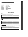
OTIS MODERNIZATION
DATE: October 19, 2007
TO:
El Paso County Courthouse
500 East San Antonio
El Paso, Texas 79901
FROM:
Otis Elevator Company
6400 Airport Road
El Paso, Texas 79925
PROJECT LOCATION:
500 East San Antonio
El Paso, Texas 79901
MACHINE NUMBER(S):
PROPOSAL NUMBER:
CT-0001
We will provide labor and material to furnish and install on the above referenced machine(s) the following:
ELEVONIC® 411M-MS CONTROL SYSTEM
SIX (6) CAR GROUP MAIN PASSENGER ELEVATORS
We propose to furnish labor and material to provide an Elevonic® 411M-MS control system. It is a digital closed-loop
microprocessor-based control system specifically designed to meet the particular needs of modernizing UMV traction
elevators. The system is a distributed network of modular microprocessor control units and solid-state performance
measurement devices. The system is integrated using serial-link communication. The control system has a Solid-State
Safety Circuit. The measurement transducers constantly monitor the performance of every elevator function controlled
by microprocessor. The control units evaluate this performance information and automatically adjust performance as
necessary to correct variances within milliseconds. The “Relative System Response Plus” software dispatches elevators
based upon real-time response to actual demands on the elevator group. The software is designed to maintain optimum
elevator system performance by evaluating and reassigning hall calls within milliseconds of changes in elevator demand
or performance.
ELEVONIC® 411M-VF CONTROL SYSTEM
MAIN SERVICE ELEVATOR & EAST/WEST PRISON ELEVATORS
We propose to furnish labor and material to provide an Elevonic® 411M-VF control system. It is a digital closed-loop
microprocessor-based control system specifically designed to meet the particular needs of modernizing UMV traction
elevators. The system is a distributed network of modular microprocessor control units and solid-state performance
measurement devices. The system is integrated using serial-link communication. The control system has a Solid-State
Safety Circuit. The measurement transducers constantly monitor the performance of every elevator function controlled
by microprocessor. The control units evaluate this performance information and automatically adjust performance as
necessary to correct variances within milliseconds. The “Relative System Response Plus” software dispatches elevators
based upon real-time response to actual demands on the elevator group. The software is designed to maintain optimum
elevator system performance by evaluating and reassigning hall calls within milliseconds of changes in elevator demand
or performance.
© OTIS ELEVATOR COMPANY, 1992
All Rights Reserved
Impact Form 421MD (12/05) Proposal#
CT-0001
Page 1 of 19
TITLE
PAGE No.
SECTION I
OPERATION
SECTION II
MACHINE ROOM EQUIPMENT
SECTION III
SYSTEM OPERATING FEATURES
SECTION IV
DOOR EQUIPMENT
SECTION V
HOISTWAY EQUIPMENT
SECTION VI
FIXTURES
SECTION VII
GENERAL REQUIREMENTS
SECTION VIII
ALTERNATES
OTIS MODERNIZATION
SECTION No.
SECTION I: OPERATION
DUTY
The present capacity and speed of the elevators will be retained as follows:
Elevators numbered
Capacity (pounds)
Speed (Feet per Minute)
Main Passenger Elevators
3,500
700
Service Elevator
6,000
350
East & West Prison Elevators
2,000
350
TRAVEL
The present travel of the elevators will be retained as follows:
Elevators numbered
From floor to floor
Approximately Rise (feet)
Main Passenger Elevators
LL to 12, LL to M
200 feet
Service Elevator
LL to 12
200 feet
East & West Prison Elevators
LL to 11
200 Feet
STOPS AND OPENINGS
The present stops and openings will be retained for Main Passenger Elevators and Service Elevator. One additional stop
and opening will be provided at the 4th floor for the East and West Prison Elevators:
Elevators numbered
Number of stops
Number of openings
Main Passenger Elevators
13 Front, 14 Front
13 Front, 14 Front
Service Elevator
13 Front
13 Front
© OTIS ELEVATOR COMPANY, 1992
All Rights Reserved
Impact Form 421MD (12/05) Proposal#
CT-0001
Page 2 of 19
10 Front (one new)
10 Front (one new)
POWER SUPPLY
The power supply of 460 volts, 3 phase, 60 hertz, alternating current will be retained with the new equipment arranged
for this power supply.
NEW DRIVE SYSTESM MAINE PASSENGER ELEVATORS
The present motor drive system will be changed to a Solid-State Direct Motor Drive.
NEW DRIVE SYSTEM SERVICE & PRISON ELEVATORS
The present motor drive system will be changed to a Variable Voltage Variable Frequency Self Commissioning NonRegenerative Drive.
NEW OPERATION ALL
The present control system will be changed to Elevonic® Microprocessor control.
CONTROLLER ALL
A microcomputer-based control system shall be provided to perform all of the functions of elevator motion and elevator
door control. This shall include all of the hardware required to connect, transfer and interrupt power, and protect the
motor against overloading. The system shall also perform car operational control.
Each controller cabinet containing memory equipment shall be properly shielded from line pollution. The
microcomputer system shall be designed to accept reprogramming with minimum system downtime.
OPERATION ⎯ ONE CAR – SERVICE & PRISON ELEVATORS
Operation shall be automatic by means of the car and landing buttons. Stops registered by the momentary actuation of
the car or landing buttons shall be made in the order in which the landings are reached in each direction of travel after the
buttons have been actuated. All stops shall be subject to the respective car or landing button being actuated sufficiently
in advance of the arrival of the car at that landing to enable the stop to be made. The direction of travel for an idle car
shall be established by the first car or landing button actuated.
“UP” landing calls shall be answered while the car is traveling in the up direction and “DOWN” landing calls shall be
answered while the car is traveling down. The car shall reverse after the uppermost or lowermost car or landing call has
been answered and then proceed to answer car calls and landing calls registered in the opposite direction of travel.
If the car without registered car calls arrives at a floor on which both up and down hall calls are registered, it shall
initially respond to the hall call in the direction that the car is traveling. If no car call or hall call is registered for further
travel in that direction, the car shall close its doors and immediately reopen them in response to the hall call in the
opposite direction. Direction lanterns, if furnished, shall indicate the change in direction when the doors reopen.
An Independent Service switch shall be provided in the car operating panel which, when actuated, shall cancel
previously registered car calls, disconnect the elevator from the hall buttons and allow operation from the car buttons
only.
OPERATION ⎯ GROUP CONTROL FOR 6 CARS MAIN PASSENGER ELEVATORS
When the cars are at rest, they shall be assigned throughout the building to predetermined zones. The first car entering a
zone shall become assigned to that zone. A car may run through an occupied, assigned zone in search of an unoccupied
zone in which to park. While there are no calls registered the cars shall remain in a parked condition with doors closed.
The lowest zone shall consist of the main floor and an adjacent floor, above or below, as required to suit building design
requirements. The remaining floors shall be divided into nearly equal zones with one car randomly assigned to each
zone.
© OTIS ELEVATOR COMPANY, 1992
All Rights Reserved
Impact Form 421MD (12/05) Proposal#
CT-0001
Page 3 of 19
OTIS MODERNIZATION
East & West Prison Elevators
RSR computations for each hall call are repeated several times a second and the hall call assignment might be changed if
a more suitable car is found.
A car without registered car calls arriving at a floor on which both up and down hall calls are registered shall initially
respond to the hall call in the direction that the car was traveling. If no car call or hall call is registered for further travel
in that direction, the car shall close its doors and immediately reopen them in response to the hall call in the opposite
direction. Direction lanterns, if furnished, shall indicate the change in direction when the doors reopen.
If for any reason the doors are prevented from closing and the car is unable to respond to a call, the call shall be
transferred to another car.
When a car is filled to a predetermined load setting, it shall no longer stop for hall calls.
When the Independent Service switch in the car operating panel is actuated, the elevator shall be disconnected from the
hall buttons and operate independently from car buttons only.
SECTION II:
MACHINE ROOM EQUIPMENT
NEW DIRECT DRIVE MAIN PASSENGER ELEVATORS
A new SCR-based direct drive system shall be provided. The system shall be regenerative. The system shall included
the drive isolation transformer and filter.
NEW DRIVE SYSTEM SERVICE & PRISON ELEVATORS
The present motor drive system will be changed to a Variable Voltage Variable Frequency Self Commissioning NonRegenerative Drive. The system shall include a step up or down transformer as required.
POWER CONVERTER SUCCESSIVE STARTING
When all power converters in a group are shut down due to lack of demand, only a single converter shall be allowed to
start up at one time.
RETAIN MACHINES - ALL
The existing machine shall be retained.
RETAIN DC MOTORS MAIN PASSENGER ELEVATORS
The existing motors shall be retained and reused.
NEW AC MOTORS SERVICE & PRISON ELEVATORS
A new 380 volt Alternating Current Variable Frequency 3 phase low slip motor will be provided.
RETAINED GOVERNOR - ALL
The present speed governor shall be retained and calibrated for the proper tripping speed.
© OTIS ELEVATOR COMPANY, 1992
All Rights Reserved
Impact Form 421MD (12/05) Proposal#
CT-0001
Page 4 of 19
OTIS MODERNIZATION
Optimized response to hall calls shall be achieved by computing a relative system response (RSR) time for each
registered hall call. This software dispatches cars by computing a relative system response for each registered hall call.
The computation of each car’s RSR time to a call shall be based on, but not limited to, such relevant factors as distance,
service to previously assigned car and hall calls, car load, direction, door and car motion status, and coincidence of car
and hall calls. The car with the least RSR time/value shall have this call assigned to it.
SYSTEM OPERATING FEATURES
NEW AUTOMATIC SELF-LEVELING - ALL
The elevator shall be provided with automatic self-leveling that shall typically bring the elevator car level with the floor
landings + ¼” regardless of load or direction of travel. The automatic self-leveling shall correct for over travel or under
travel and rope stretch.
NEW MODERATE UP AND MODERATE DOWN TRAFFIC PROGRAM - ALL
When incoming traffic at the lobby floor increases, as indicated by two cars leaving the lobby in the “UP” direction and
filled nearly to capacity within a predetermined adjustable time period, cars assigned to upper zones shall be called to the
lobby without waiting for a lobby hall call.
Cars shall be dispatched automatically from the lobby when they become loaded nearly to capacity or, if not loaded to
capacity, shall be dispatched within a predetermined time after the previous car has been dispatched. The cars shall
continue to operate in this manner until the lobby traffic has been reduced to a predetermined level.
When “DOWN” calls above the lobby increase to a predetermined level, assignment of a car to the lobby ceases and the
lobby car shall travel up to assist the other cars. Cars arriving at the lobby after discharging passengers shall be
dispatched upward. The cars shall continue to operate in this manner until the down traffic has been reduced to a
predetermined level.
NEW CLOCK DOWN PEAK - ALL
To prepare the system for heavy outgoing traffic, operation shall be such that upon the arrival at the lobby of any car
loaded more than a predetermined capacity during a preset clock period, assignment of a car to the lobby ceases and the
lobby car shall travel up to assist the other cars. Cars arriving at the lobby after discharging passengers shall be
dispatched upward. The cars shall continue to operate in this manner until the end of the clock period.
NEW UP HALL-CALL BYPASS - ALL
During clock-down peak operation, any car traveling down with a non-stop load will cause other cars to bypass up hall
calls. The number of cars operating in this bypass mode is adjustable as a function of building traffic. This operation
remains in effect for an adjustable period of time after the last bypass operation.
NEW CLOCK UP PEAK - ALL
To maintain sufficient lobby car capacity to handle anticipated heavy incoming traffic, the operation shall be such that
when incoming traffic at the lobby floor increases, as indicated by a car leaving the lobby in the “UP” direction filled to
a predetermined capacity during a preset clock period, all cars shall be returned to the lobby without waiting for a lobby
hall call.
Cars shall be dispatched automatically from the lobby when they become loaded nearly to capacity or, if not loaded to
capacity, on a variable time interval calculated on the basis of the number of cars at the lobby and other data
representative of traffic in the system. The cars shall continue to operate in this manner until the end of the clock period.
NEW NO-LOBBY-CAR BYPASS - ALL
The no-lobby car bypass speeds the return of cars to a vacant lobby during up peak operation. In the absence of a lobby
car, cars will travel only to the highest car call and reverse to the lobby. Cars will bypass hall calls, stopping only in
response to car calls. This operation will remain in effect until a car arrives at the lobby.
NEW CAR-TO-LOBBY OPERATION - ALL
A key switch shall be provided for each elevator at the main floor. Its actuation shall cause the corresponding elevator to
make a trip to the lobby as soon as the car is available for response to the special call.
NEW SPECIAL EMERGENCY SERVICE - ALL
Special Emergency Service operation shall be provided in compliance with the latest applicable revision of the
ASME/ANSI A17.1 Code.
© OTIS ELEVATOR COMPANY, 1992
All Rights Reserved
Impact Form 421MD (12/05) Proposal#
CT-0001
Page 5 of 19
OTIS MODERNIZATION
SECTION III:
The smoke detector system, if required, is to be furnished by others. The elevator contractor shall provide contacts on
the elevator controller to receive signals from the smoke detector system.
A keyswitch in the car shall be provided for in-car control of each elevator when on Phase II of Special Emergency
Service.
If an elevator is on independent service when the elevators are recalled on Phase I operation, a buzzer shall sound in the
car and a jewel shall be illuminated, subject to applicable codes.
NEW INSPECTION OPERATION - ALL
For inspection purposes, an enabling keyswitch shall be provided in the car operating panel to permit operation of the
elevator from on top of the car and to make car and hall buttons inoperative.
An operating fixture shall be provided on top of the car containing continuous pressure “UP” and “DOWN” buttons, an
emergency stop button, and a toggle switch. This toggle switch makes the fixture operable and, at the same time, makes
the door operator and car and hall buttons inoperable.
NEW ANTI-NUISANCE - ALL
An anti-nuisance feature shall be provided, which will reset car buttons and require re-registration if an excessive
number of calls are registered for the measured load.
NEW EXPRESS PRIORITY SERVICE MAIN PASSENGER ELEVATORS
A key switch and signal light shall be provided at designated landings to permit an available elevator to be called to that
landing, canceling all car calls and bypassing all hall calls along the way. When the car arrives, it shall remain with
doors open for a predetermined time to permit the car to be placed on Emergency Priority Service. If not placed on this
service, the doors shall close and the car shall automatically return to normal operation.
The signal lights shall be illuminated while a car is responding to a priority call and will be extinguished when the car
has been placed on Emergency Priority Service or has been returned to normal service.
If there is no car available for this priority service, the signal lights shall remain illuminated until a car becomes available
to receive a priority service call.
Another priority call cannot be initiated until the signal lights are extinguished.
NEW HOISTWAY ACCESS SWITCHES - ALL
An enabling keyswitch shall be provided in the car operating panel to render all car and hall buttons inoperative and to
permit operation of the elevator by means of an access keyswitch adjacent to the hoistway entrance at the access landing.
The movement of the car away from the access landing, other than the lower terminal, by means of the access keyswitch
at the landing shall be limited in travel and direction to that as specified for the upper landing in the latest applicable
revision of the ASME/ANSI A17.1 Code.
NEW REMOTE ELEVATOR MONITORING MAINTENANCE - ALL
A microprocessor system that continuously monitors the Unit(s) on a 24-hour per day, year-round basis will be provided.
The system will notify a dispatching center that the elevator is inoperative by sending a message via telephone line
(Provided by others. See “Work By Others” section.) This makes it possible to have a mechanic dispatched rapidly in
response to such a message.
The monitoring system will collect data on the equipment condition whether the operation of a Unit has been interrupted.
The monitoring equipment will remain the property of the elevator contractor.
For the telephone line requirements see the “Work By Others” section
© OTIS ELEVATOR COMPANY, 1992
All Rights Reserved
Impact Form 421MD (12/05) Proposal#
CT-0001
Page 6 of 19
OTIS MODERNIZATION
Special Emergency Service Phase I to return the elevator(s) non-stop to a designated floor shall be initiated by an
elevator smoke detector system or a keyswitch provided in a lobby fixture.
A manual selector switch shall be provided at the main floor. The switch will contain a contact position for each elevator
and an “AUTOMATIC” position, permitting one selected elevator to remain on standby power or to provide power to an
elevator that has been out of service when the elevators were being returned automatically.
SECTION IV:
DOOR EQUIPMENT
RETAIN DOOR OPERATORS MAIN PASSENGER ELEVATORS
The present door operators shall be retained and modified to include evacuation deterrent devices on each hoistway door
as required by code.
NEW DIGITAL CLOSED-LOOP CONTROL SYSTEM FOR RETAINED DOOR OPERATOR MAIN
PASSENGER ELEVTORS
Replace existing electro-mechanical controls with a digital closed-loop solid-state control system. The new control
system will provide closed loop control continuously for both the velocity and position of the doors, enabling the doors
to adhere to a pre-defined opening and closing profile. A new motor and gate switch will also be provided. All other
door operator and hoistway components will be retained.
NEW DOOR OPERATOR i-MOTION® II SERVICE & PRISION ELEVATORS
A new i-MOTION® II door operator shall be installed.
Doors on the car and at the hoistway entrances shall be power operated by means of i-MOTION II door operator
mounted on top of the car. The door operator is a fully closed loop system designed to give consistent door performance
with changes in temperature, wind or minor debris in the door track. The system continually monitors door speed and
position and adjusts it accordingly to match the pre-determined profile.
Door operation shall be automatic at each landing with door opening being initiated as the car arrives at the landing and
closing taking place after expiration of an adjustable time interval. An electric car door contact shall prevent the elevator
from operating unless the car door is in the closed position.
Door close shall be arranged to start after a minimum time, consistent with Handicap Requirements.
Doors shall be arranged to remain open for an adjustable time period sufficient to meet ADA requirements.
The time interval for which the elevator doors remain open when a car stops at a landing shall be independently
adjustable for response to car calls and response to hall calls.
RETAIN INTERLOCKS - ALL
The present interlocks shall be retained and refurbished as necessary.
NEW LAMBDA® 3D DOOR-PROTECTION DEVICE - ALL
A solid state, infrared passenger protection device shall be installed on the car door. This device provides 56 infrared
light beams that create an invisible safety net across the elevator entrance. In addition, LAMBDA® 3D adds a triangular
coverage area to protect passengers approaching or exiting the landing door zone or entryway. The LAMBDA 3D system
aims 12 additional infrared beams out into the entryway at a nominal 30 degree angle away from the direction of door
travel. If these beams strike an object in the middle of the entryway, some of the light is reflected into special photodiode receivers which scan into the entryway at a nominal 30 degree angle. If the receivers detect enough light, a
reversal signal is generated to open the doors. The maximum projection of these 12 additional beams at any time is onethird of the door opening width.
© OTIS ELEVATOR COMPANY, 1992
All Rights Reserved
Impact Form 421MD (12/05) Proposal#
CT-0001
Page 7 of 19
OTIS MODERNIZATION
NEW STANDBY POWER OPERATION (AUTOMATIC SELECTION) MAIN PASSENGER ELEVATORS
The elevators shall return automatically to the main floor at full rated speed, one at a time during emergency power
operation. A car that is out of service for other reasons shall be bypassed and another car selected.
Graceful degradation operation is also included. If one or two isolated beams (up to a maximum of 36 beams) are
interrupted, LAMBDA 3D’s door-reversal signal will cause the doors to reopen instantly. If the beams remain blocked
for more than 80 seconds, the beams are considered permanently blocked. LAMBDA 3D then ignores these blockages
and the detector will continue to operate as it would without any blockages.
If three or more adjacent beams are interrupted, LAMBDA 3D’s door-reversal signal will cause the doors to reopen
instantly. If they remain blocked for more than 80 seconds, they are considered permanently blocked. The doors will
then either remain open indefinitely, go into nudging mode or remain open for a specified period of time, depending on
local codes and the door operating system. The doors will remain in this mode until the blockage is corrected.
NUDGING OPERATION
If during a hall or car call the car doors are prevented from closing for a fixed time period, the door protective device
shall be rendered inoperative, a buzzer shall sound on the car and the doors shall close at a slower speed. Operation of
the door protective device shall resume at the next landing reached by the car.
RETAIN CAR DOOR HANGERS - ALL
The present car door hangers shall be retained.
RETAIN HOISTWAY ENTRANCES - ALL
The present hoistway entrances shall be retained.
NEW HOISTWAY ENTRANCES PRISON ELEVATORS
New hoistway entrances shall be installed at the 4th floor for both the East and West Prison elevators. The entrances
shall be manufactured to match existing. All associated door equipment shall be included at time of installation.
RETAINED HOISTWAY DOOR HANGER - ALL
The present hoistway door hanger shall be retained. They shall be inspected.
SECTION V: HOISTWAY EQUIPMENT
NEW HOISTWAY OPERATING DEVICES - ALL
Terminal stopping devices shall be provided to slow or automatically stop the car at the terminal landings and to
automatically cut off the power and apply the brake, should the car travel beyond the terminal landings.
RETAIN CAR GUIDES - ALL
The existing car guides shall be retained. They shall be inspected.
RETAIN CAR FRAME AND SAFETY - ALL
The existing car safety device, designed to stop the car if it attains a descending speed in excess of the preset contract
speed, shall be retained.
RETAIN ROPES SERIVCE & PRISON ELEVATORS
The existing hoist ropes shall be retained. They shall be inspected.
© OTIS ELEVATOR COMPANY, 1992
All Rights Reserved
Impact Form 421MD (12/05) Proposal#
CT-0001
Page 8 of 19
OTIS MODERNIZATION
If any beam is interrupted, LAMBDA 3D’s door-reversal signal will cause the elevator doors to reopen instantly without
touching the passenger. After a car stop is made, the door shall remain open for a predetermined interval before closing.
If, while the door is closing, the matrix of invisible light beams is interrupted by a passenger entering or leaving the car,
the door shall stop and reopen, after which the door shall again start to close.
New hoistway ropes shall be installed to accommodate the installation of rope grippers as a result of raising the existing
hoist machines. The replacement ropes shall be traction steel of size, construction and number to ensure proper
operation of the elevator and give satisfactory wearing qualities. All ropes shall consist of at least eight strands wound
around a hemp core.
RETAIN SOUND-ISOLATED PLATFORM - ALL
The existing sound-isolated frame will be retained and reused.
RETAIN CAR INTERIOR WITH ALTERATIONS - ALL
The existing elevator car interiors shall be modernized as part of this project. A cab allowance of $20, 000 per elevator
is included in this proposal. Owner to select finishes.
NEW LOAD-WEIGHING DEVICE - ALL
A platform load weighing device set to operate at a predetermined fixed percentage of the car load shall be provided.
NEW PIT SWITCH - ALL
An emergency stop switch shall be located in the pit and accessible from the pit access door.
RETAIN BUFFERS - ALL
The existing buffers shall be retained.
SECTION VI:
FIXTURES
CAR FIXTURES:
NEW MAIN SWING FRONT CAR OPERATING PANEL PASSENGER ELEVATORS
A swing front car operating panel shall be furnished. The panel shall contain a bank of mechanical illuminated buttons
marked to correspond with the landings served, an emergency call button, emergency stop button, door open and door
close buttons, and a light switch. The emergency call button shall be connected to a bell that serves as an emergency
signal.
NEW AUXILLARY SWING FRONT RETURN CAR OPERATING PANEL PASSENGER ELEVATORS
A auxiliary swing front return car operating panel shall be furnished. The panel shall contain a bank of mechanical
illuminated buttons marked to correspond to the landings served, emergency call button, emergency stop button, door
open and door close buttons.
NEW APPLIED CAR OPERATING PANEL SERVICE & PRISON ELEVATORS
An applied car operating panel shall be furnished. The panel shall contain a bank of mechanical illuminated buttons
marked to correspond with the landings served, an emergency call button, emergency stop button, door open and door
close buttons, and a light switch. The emergency call button shall be connected to a bell that serves as an emergency
signal. A fan switch, if optional fan is provided, shall also be located in the car operating panel.
NEW APPLIED CAR OPERATING PANEL PRISON ELEVATORS
An applied car operating panel shall be furnished and installed at the EL Paso County Jail in current location. The panel
shall contain a bank of mechanical illuminated buttons marked to correspond with the landings served, an emergency call
button, emergency stop button, door open and door close buttons, and a light switch. The emergency call button shall be
connected to a bell that serves as an emergency signal. An over ride3 switch shall be incorporated for total control of the
elevators.
© OTIS ELEVATOR COMPANY, 1992
All Rights Reserved
Impact Form 421MD (12/05) Proposal#
CT-0001
Page 9 of 19
OTIS MODERNIZATION
NEW ROPES MAIN PASSENGER ELEVATORS
NEW OTIS HANDSOFF® PHONE - ALL
We propose to furnish and install the Otis HANDSOFF® phone. The HANDSOFF phone is a telephone which enables
communication between persons in the elevator and a 24-hour answering service.
The HANDSOFF phone will be mounted in a telephone box or surface mounted in the elevator cab. It will automatically
dial a preprogrammed number and will inform the answering service of the elevator location via prerecorded digital
voice communication. After disclosing the elevator location, the phone will allow two-way voice communication. The
HANDSOFF phone contains two light-emitting diodes -- one that indicates the call is in progress and another that
indicates the call has been acknowledged. After receiving acknowledgment of the call from the answering service, a
deaf/mute person can signal the answering service by reactivating the call button. The phone can be easily programmed
and allows incoming calls to be received. The telephone will be furnished and installed in accordance with the ASME
A17.1 Safety Code for Elevators and Escalators, and is registered with the FCC.
NEW CAR POSITION INDICATOR - ALL
A car position indicator shall be installed. The position of the car in the hoistway shall be shown by illumination of the
indication corresponding to the landing at which the car is stopped or passing.
NEW AUDIBLE SIGNAL (INDICATES PASSING OR STOPPING AT A LANDING) SERVICE & PRISON
ELEVATORS
An audible signal shall sound in the car to tell passengers that the car is either stopping or passing a landing served by
the elevator.
NEW AUDIBLE VOICE SIGNAL MAIN PASSENGER ELEVATORS
Equipment shall be furnished to allow an audible announcement in each car of the name of the next selected landing at
which the elevator will stop and the committed direction of travel. Several advisory messages shall also be available to
indicate the need for elevator on special service or passenger delay of elevator.
NEW “IN-CAR” DIRECTION LANTERNS SERVICE & PRIOSN ELEVATORS
Direction lantern shall be mounted in car entrance jamb, visible from the corridor, which when the car stops and the
doors are opening, shall indicate the direction the car is traveling. A chime shall also be furnished on the car that will
sound once for the “UP” direction and twice for the “DOWN” direction as the doors are opening.
HALL FIXTURES:
NEW HALL BUTTONS - ALL
New hall buttons shall be installed at each landing. An up button and a down button at each intermediate landing and a
single button at each terminal landing shall be installed.
A call shall be registered by momentary pressure of a landing button. The button shall become illuminated and remain
illuminated until the call is answered.
FOUR HALL BUTTON RISER MAIN PASSENGER ELEVATORS
Four risers of illuminated hall buttons shall be provided.
RETAIN HALL LANTERNS WITH ALTERATIONS MAIN PASSENGER ELEVATORS
The existing hall lanterns will be retained and refurbished using new LED lights and electronic chimes.
© OTIS ELEVATOR COMPANY, 1992
All Rights Reserved
Impact Form 421MD (12/05) Proposal#
CT-0001 Page 10 of 19
OTIS MODERNIZATION
NEW EMERGENCY CAR LIGHTING - ALL
An emergency power unit employing a 12-volt sealed rechargeable battery and totally static circuit shall be provided.
The power unit shall illuminate the elevator car and provide current to the alarm bell in the event of normal power
failure. The equipment shall comply with the requirements of the latest applicable revision of the ASME/ANSI A17.1
Code.
Hall position indicators with stainless steel faceplates shall be installed at all landings. The position of the car in the
hoistway shall be shown by the illumination of the indicator corresponding to the landing that the car is stopped or
passing.
NEW LOBBY PANEL MAIN PASSENGER & SERVICE ELEVATORS
A lobby panel shall be provided with key-operated switches to shut down each elevator. A pilot light shall be provided
to indicate when the elevator is operational. This panel will also contain the key-operated switches for car-to-lobby
operation, emergency power operation, etc. The new panel shall be located at the existing location.
ELEVATOR MANAGEMENT SYSTEM
MAIN PASSENGER, SERVICE & PRISON ELEVATORS
The EMS Panorama™ system is a Web-based management application that enables building personnel to securely
monitor and control elevators, escalators and moving walks from virtually any location using a computer with a standard
Internet browser.
The EMS Panorama system can display the real-time equipment status for a single building or multiple buildings
including an entire airport, college campus, or medical center. It enables building management, security and engineering
personnel to remotely observe performance and modify control settings. Users can generate a variety of reports on
system performance, such as system availability, alarms and alerts. The system also incorporates scheduling features
that enable users to accommodate changes in traffic patterns and to implement a variety of special operational modes
such as “up peak” performance and after-hours security and access settings.
The EMS Panorama system is an on-site system that consists of hardware and software, which can be customized to
meet the user’s needs. In its most basic form, EMS Panorama provides a display for monitoring current elevator status.
In its most robust form, it can be configured to be an interactive, computer-based elevator monitoring, communications
and performance analysis system with multiple display terminals. The actual capabilities of the system shall be
described herein:
Remote and Web-Based Capability Via Modem and Building Networks (LAN): Auxiliary stations can connect to
the main station using a building network or a private network created by Otis. Remote access is also possible using a
common phone line, broadband connection or DSL, providing the customer allows remote access to their Intranet.
Training Tools: Includes fully integrated online help, as well as a comprehensive computer based training (CBT)
module installed on each PC. A copy of the CBT on CD-ROM will be shipped with each EMS Panorama system,
allowing users the flexibility to conduct training on any PC.
Monitoring: The monitoring function is capable of displaying the operational status of all the elevators, escalators and
moving walkways by group. It displays several graphical views of all-important operational information in real-time.
Also included is operational status information such as in operation or not, operation floor, direction, opening/closing of
door, car calls, hall calls, car security and hall security. This information is provided on a graphic screen.
Real Time Displays
Real-time display is available in group, summary, or campus views and provides the following capabilities:
• Monitor elevators, escalators and moving walkways
• Ability to combine up to 8 elevators from different groups into a logical group for display purposes
• Tool tips to display full descriptions of group and car mode abbreviations
• Smooth on-screen movement of elevator moving up and down the hoistway
• Acceleration of car image for realistic elevator display
• Ability to load logo or building image to be used as background picture for group display
© OTIS ELEVATOR COMPANY, 1992
All Rights Reserved
Impact Form 421MD (12/05) Proposal#
CT-0001 Page 11 of 19
OTIS MODERNIZATION
NEW HALL POSITION INDICATOR SERVICE ELEVATOR
2.) Group Display: A smooth-moving, graphical representation of every car in a group will be shown (one group at
a time) so that the following information can be viewed:
• Floor status: floors served, floors secured
• Group operational mode (e.g., up peak, special emergency service, emergency power)
• Car status: operational mode (e.g., in group, independent service, inspection); car calls registered; position
and direction; door status (open, opening, closed, closing); load (normal, full, overload)
• Hall calls shall be indicated
• Date, time and building/group shall be indicated
3.) Campus Display: A campus display feature is available and has been added as a standard offering configured
by Otis.
Additional Features
Playback: Monitoring data is stored so that it can be played back at a later time. Two kinds of screens can be displayed
in playback:
• Summary display plays status summary and operational information for elevators in all groups by selected
time conditions.
• Group display plays the setting status of the car and hall as well as the detailed operational information for
elevators in the group selected by the user for the selected time conditions.
The playback function includes the following capabilities:
• Rewind and fast-forward functions to locate exact point in time that is needed
• EMS Panorama main station does not have to be brought offline to perform playback function
• Ability to playback any data that is stored in the database regardless of how old the data may be
• Definable date range is available
Elevator Alarm and Event Data: EMS Panorama monitors various discrete signals from the elevator system. When
an alarm or event occurs, its date, time, location and type will be logged. The last 1,000 alarms/events are retained in the
log. Alarms are configured with audible .wav-format files.
Security Operation Display: This display allows modification of the security status of the cars in each group connected
to the system. Modification can only be performed one group at a time. For each car, the floors it serves and the floors
that can be secured will be indicated. Both hall and car calls can be secured, however only car calls can be selected on a
per car basis.
REMOTE VIDEO CAMERA SYSTEM
MAIN PASSENGER & SERVICE ELEVATORS
The Otis® Remote Video Camera System allows for remote viewing and recording of activity in the elevator. We will
install the Otis Remote Video Camera System in the main passenger and service elevators. The existing camera system
in the prison elevators shall be retained and reused.
The Remote Video Camera System will consist of a corner-mount camera in the corner of each elevator cab. The
cameras will be connected to the digital video recorder (DVR). Each DVR can record up to four cameras simultaneously
for up to 30 days on its internal hard drive. When the hard drive is full, the DVR will continue recording, overwriting
the earliest recordings. The viewing monitor will also be located in the same location as the DVR.
The DVR is pre-programmed with the following settings:
Recording modes available:
1. Continuous 24-hour recording
2. Scheduled recording
3. Motion-detection recording
Frames per second available:
© OTIS ELEVATOR COMPANY, 1992
All Rights Reserved
Impact Form 421MD (12/05) Proposal#
CT-0001 Page 12 of 19
OTIS MODERNIZATION
1.) Summary Display: Displays (in a tabular format) where the elevator is located (which floor), door status, car
mode, and alarm or event status.
2
5
10
It will be possible to view all cameras on the screen simultaneously.
A user’s manual will be supplied with the DVR to highlight key features and operation of the DVR, including how to
password-protect the menu screens and how to change recording parameters.
Work by others:
I.
The wiring to connect the security camera from the machine room to the DVR located in a remote
location, as well as the wiring to connect the DVR to the monitor and VCR in the remote location.
II.
115 VAC in the remote location for the DVR, monitor and VCR.
III.
Space for the DVR and monitor in the remote location
IV.
Wiring for to connect the VCR to the DVR, as well as 115 VAC power for the VCR.
V.
Space for the VCR in the remote location
OTIS 211M HYDRAULIC CONTROL SYSTEM
LOADING DOCK HYDRAULIC ELEVATOR
We propose to furnish labor and material to provide a hydraulic microprocessor-based control system. It is specifically
designed to meet the particular needs of modernizing hydraulic elevators. The system is integrated by communications
over serial links and discrete wiring. The "Relative System Response Plus" software dispatches elevators based upon
real-time response to actual demands on the elevator(s).
DUTY
The present capacity of 2,000 pounds at 75 feet per minute will be retained.
TRAVEL
The present travel from LL to 1st floor, a rise of 12 feet , will be retained.
STOPS AND OPENINGS
The present 2stops and 2 openings will be retained.
RETIAN POWER SUPPLY
The present power supply of 460 volts, 3 phase, 60 hertz, alternating current will be retained and the new equipment will
be arranged for this power supply.
NEW SOFT STARTER
A new solid-state starter will be provided. It will be of the same power requirement and starting configuration as
presently exists.
NEW MOTOR
The existing motor will be replaced with a motor that is of the same power characteristics and starting configuration as
presently exists.
NEW POWER UNIT
The existing power unit will be replaced with a new power unit. The new power unit consists of a positive displacement
pump, motor, integral 4-coil control valve, oil tank and muffler. The pump and motor are submerged and are mounted to
the tank with rubber isolators to reduce vibration and noise
© OTIS ELEVATOR COMPANY, 1992
All Rights Reserved
Impact Form 421MD (12/05) Proposal#
CT-0001 Page 13 of 19
OTIS MODERNIZATION
4.
5.
6.
A new integral 4-coil control valve will be installed to replace the existing valve. The valve consists of up, up leveling,
down and down leveling controls along with manual lowering and a pressure relief valve.
NEW AUTOMATIC SELF-LEVELING (WITH NEW HOISTWAY LEVELING DEVICE)
The elevator shall be provided with automatic self-leveling that shall bring the elevator car level with the floor landings,
no more than +/- 1/2" regardless of load or direction of travel. The automatic self-leveling shall correct for over travel or
under travel.
NEW CONTROLLER
A microprocessor-based control system shall be provided to perform all the functions of safe elevator motion and
elevator door control. This shall include all the hardware required to connect, transfer and interrupt power, and protect
the motor against overloading. The system shall also perform group operational control.
Each controller cabinet containing memory equipment shall be properly shielded from line pollution. The
microcomputer system shall be designed to accept reprogramming with minimum system downtime.
OPERATION - ONE CAR
Operation shall be automatic by means of the car and landing buttons. Stops registered by momentary actuation of the
car or landing buttons shall be made in the order in which the landings are reached in each direction of travel after the
buttons have been actuated. All stops shall be subject to the respective car or landing button being actuated sufficiently
in advance of the arrival of the car at that landing to enable the stop to be made. The direction of travel for an idle car
shall be established by the first car or landing button actuated.
“UP” landing calls shall be answered while the car is traveling in the up direction and “DOWN” landing calls shall be
answered while the car is traveling down. The car shall reverse after the uppermost or lowermost car or landing call has
been answered, then proceed to answer car calls and landing calls registered in the opposite direction of travel.
If the car without registered calls arrives at a floor where both up and down hall calls are registered, it shall initially
respond to the hall call in the direction that the car was traveling. If no car call or hall call is registered for further travel
in that direction, the car shall close its doors and immediately reopen them in response to the hall call in the opposite
directions. Direction lanterns, if furnished, shall indicate the change of direction when the doors reopen.
An independent service switch shall be provided in the car operating panel which, when actuated, shall cancel previously
registered car calls, disconnect the elevator from the hall buttons and allow operation from the car buttons only.
OTIS REM® MAINTENANCE
We will provide a microprocessor system that continuously monitors the Unit(s) on a 24-hour per day, year-round basis.
The system will notify our OTISLINE® dispatching center that a Unit is inoperative by sending a message via telephone
line. Upon the receipt of such message, we will either notify your on-site representative or initiate the dispatch of our
personnel for emergency minor adjustment callback service during regular working hours of our regular working days
for the mechanics who perform the service.
We will collect data on the equipment condition, including hydraulic tank oil level, door operation, leveling and whether
the operation of a Unit has been interrupted. That information will be used to tailor the Otis Maintenance Management
SystemSM preventive maintenance program for the Unit(s).
You will furnish us at your expense, one (1) outside telephone line to the elevator machine room that allows data calls to
and from a toll-free number at our OTISLINE dispatching center. The telephone line may be a separate line dedicated to
the REM® maintenance equipment or may be an existing line that is shared between another telephone and the REM
maintenance equipment.
© OTIS ELEVATOR COMPANY, 1992
All Rights Reserved
Impact Form 421MD (12/05) Proposal#
CT-0001 Page 14 of 19
OTIS MODERNIZATION
NEW VALVE
NEW HALL BUTTON LOADING DOCK LEVEL
New hall button shall be installed at the loading dock level. The operation of the elevator shall be constant pressure as is
existing.
NEW HOISTWAY OPERATING DEVICES
Normal terminal stopping devices shall be provided to slow down and stop the car automatically at the terminal landings
and to automatically cut off the power and apply the brake, should the car travel beyond the terminal landings.
RETAIN CAR GUIDES
The existing car guides shall be retained. They shall be thoroughly inspected. Any worn parts will be replaced by the
original manufacture parts or equal.
RETAIN CAR FRAME
The existing car frame shall be retained.
RETAIN PLATFORM
The current platform will be retained.
RETAIN FLOORING
The present flooring will be retained.
NEW INTERLOCKS
New interlocks will be installed. The interlocks shall prevent operation of the elevator unless all doors for that elevator
are closed and shall maintain the doors in their closed position while the elevator is away from the landing. Emergency
access to the hoistway as required by governing codes shall be provided.
RETAIN CAR ENCLOSURE
The present car enclosure shall be retained.
NEW MANUAL BI-PARTING FREIGHT DOORS AT LL LEVEL ONLY
A new set ob bi-parting freight doors shall be installed at the lowest level. The doors, tracks, hangers, etc. shall be
designed to match existing and work integral with the retained entrance frame.
NEW PIT SWITCH
An emergency stop switch shall be located in the pit accessible from the pit access door.
RETAIN SPRING BUFFERS
The existing spring buffers shall be retained.
© OTIS ELEVATOR COMPANY, 1992
All Rights Reserved
Impact Form 421MD (12/05) Proposal#
CT-0001 Page 15 of 19
OTIS MODERNIZATION
All of the REM maintenance monitoring equipment installed by us remains our property and if the Contract is terminated
for any reason, we will be given access to your premises to remove the monitoring equipment at our expense.
WIRING
All wiring and electrical interconnections shall comply with governing codes. Insulated wiring shall have flame
retardant and moisture-proof outer covering and shall be run in conduit, tubing or electrical wireways. Traveling cables
shall be flexible and suitably suspended to relieve strain on individual conductors.
ENGINEERING DESIGN
All new material furnished shall be specifically designed to operate with the original Otis equipment being retained, thus
assuring maximum performance and eliminating any divided responsibility.
SUPERSEDED MATERIAL
All material, removed or unused, not required in the modification will become the property of Otis Elevator Company
and we reserve the right to remove and retain it.
PERMITS AND INSPECTIONS
The elevator contractor shall furnish all licenses and permits and shall arrange for and make all required inspections and
tests.
CODE
The elevator equipment shall be furnished and installed in accordance with the applicable version of the ASME/ANSI
A17.1 Safety Code for Elevators and Escalators, An American National Standard, including the latest Supplement, and
the Americans with Disabilities Act.
CODE (LOCAL)
The elevator equipment shall comply with all applicable local codes.
WORK BY OTHERS
The following items must be performed by others and you agree to:
Provide suitable ventilation and cooling equipment, if required, to maintain the machine-room temperature between 45oF
and 95oF. The relative humidity should not exceed 85 percent non-condensing.
Provide electrical power for light, tools, hoists, etc. during installation as well as electric current for starting, testing and
adjusting the elevator.
Provide a smoke detector system, located as required with wiring from the sensing devices to each elevator controller.
Do any cutting, including cutouts to accommodate new entrances at 4th floor, hall signal fixtures, patching and painting
of walls, floors or partitions.
MAIN DISCONNECT
Provide a fused disconnect switch or circuit breaker for each elevator per the National Electrical Code with feeder or
branch wiring to the transformer. Size to suit elevator contractor.
HALL BUTTON POWER SUPPLY & DISCONNECT
Provide separate single-phase power of the same voltage as each elevator supply with a 15 amp DPST fused disconnect
switch and branch wiring to each group controller (required for two to eight car groups only).
CAR LIGHT POWER SUPPLY & DISCONNECT
Provide a 120 volt AC, 15 amp, single-phase power supply with fused SPST disconnect switch for each elevator, with
feeder wiring to each controller for car lights.
REMOTE MONITORING MAINTENANCE TELEPHONE LINE REQUIREMENTS
Provide one (1) outside telephone line to the elevator machine room that allows data calls to and from a toll-free number
at a dispatching center. The telephone line may be either a separate line dedicated to the remote monitoring maintenance
© OTIS ELEVATOR COMPANY, 1992
All Rights Reserved
Impact Form 421MD (12/05) Proposal#
CT-0001 Page 16 of 19
OTIS MODERNIZATION
SECTION VII: GENERAL REQUIREMENTS
INFORMATION DISPLAY POWER SUPPLY & DISCONNECT
Provide a separate 120 volt, AC, 15 amp, single-phase power supply with fused SPST disconnect switch with duplex
outlets in the machine room or other locations as required, for information display terminal and controller of information
display when provided. Also provide one (1) pair of shielded/twisted conductors between controller and machine room.
STANDBY POWER REQUIREMENTS
Provide a standby power unit and a means for starting it that will deliver sufficient power to the elevator disconnect
switches to operate one or more elevators at a time at full-rated speed. Provide a transfer switch for each feeder for
switching from normal power to standby (emergency) power and a contact on each transfer switch closed on normal
power supply with two wires from this contact to one elevator controller. Provide a means for absorbing power
regenerated by the elevator system when running with overhauling loads such as full load down.
Any modification or installation of lights and/or electrical outlets in the machine room and/or pit to be performed by
others.
All work will be performed during our regular working hours of our regular working days except for emergency minor
adjustment callback service which will be provided during regular working hours and also during any overtime hours.
OTIS MODERNIZATION
equipment or may be an existing line that is shared between another telephone and the remote monitoring maintenance
equipment.
All work will be performed during our regular working hours of our regular working days except for emergency minor
adjustment callback service which will be provided during regular working hours.
It is agreed that we do not assume possession or control of any part of the equipment but such remains yours exclusively
as the owner (or lessee) thereof.
We shall not be liable for any loss, damage or delay due to any cause beyond our reasonable control including, but not
limited to, acts of government, strikes, lockouts, fire, explosion, theft, floods, riot, civil commotion, war, malicious
mischief or act of God. Under no circumstances shall we be liable for consequential damages.
Deleted: ¶
© OTIS ELEVATOR COMPANY, 1992
All Rights Reserved
Impact Form 421MD (12/05) Proposal#
CT-0001 Page 17 of 19
PRICE:
$ 2,200,000.00 plus tax if applicable Firm Budget Pricing
Two Million Two Hundred Thousand Dollars
This price is based on a thirty percent (30%) downpayment in the amount of $ 660,000.00.
This proposal, including the provisions printed on the pages following, shall be a binding contract between you, or the
party identified below for whom you are authorized to contract (collectively referred to herein as :you:), and us when
accepted by you through execution of this proposal by you and approved by our authorized representative; or by your
authorizing us to perform work for the project and our commencing such work.
Submitted by: ______________________________
Carlos Trujillo
Accepted in Duplicate
CUSTOMER
Approved by Authorized Representative
OTIS ELEVATOR COMPANY
Approved by Authorized Representative
Date:
¯¯¯¯¯¯¯¯¯¯¯¯¯¯¯¯¯¯¯¯¯¯¯¯¯¯¯¯¯¯¯¯¯¯¯
¯¯¯¯¯¯¯¯¯¯¯¯¯¯¯¯¯¯¯¯¯¯¯¯¯¯¯¯¯¯¯¯¯¯¯¯
Signed:
Signed: X
¯¯¯¯¯¯¯¯¯¯¯¯¯¯¯¯¯¯¯¯¯¯¯¯¯¯¯¯¯¯¯¯¯¯
¯¯¯¯¯¯¯¯¯¯¯¯¯¯¯¯¯¯¯¯¯¯¯¯¯¯¯¯¯¯¯¯¯
Print Name: Brian Tyler
Print Name:
¯¯¯¯¯¯¯¯¯¯¯¯¯¯¯¯¯¯¯¯¯¯¯¯¯¯¯¯¯¯¯¯
¯¯¯¯¯¯¯¯¯¯¯¯¯¯¯¯¯¯¯¯¯¯¯¯¯¯¯¯¯¯¯
Title:
Title: Branch Manager
¯¯¯¯¯¯¯¯¯¯¯¯¯¯¯¯¯¯¯¯¯¯¯¯¯¯¯¯¯¯¯¯¯¯¯¯
¯¯¯¯¯¯¯¯¯¯¯¯¯¯¯¯¯¯¯¯¯¯¯¯¯¯¯¯¯¯¯¯¯¯¯¯
Name of Company:
¯¯¯¯¯¯¯¯¯¯¯¯¯¯¯¯¯¯¯¯¯¯¯¯¯¯¯¯¯¯¯¯¯¯¯¯¯¯¯¯¯¯¯¯¯¯¯¯¯¯¯¯¯¯¯¯¯¯¯¯¯¯¯¯¯¯¯¯¯¯
Date:
Principal, Owner or
Authorized Representative of Principal or Owner
Agent
(Name of Principal or Owner)
© OTIS ELEVATOR COMPANY, 1992
All Rights Reserved
Impact Form 421MD (12/05) Proposal#
CT-0001 Page 18 of 19
OTIS MODERNIZATION
The extent of the work to be performed is either described above or in the attached specification which is incorporated
into and made a part of this document.
The work shall be performed for the agreed price plus any applicable sales, excise or similar taxes as required by law.
In addition to the agreed price, you shall pay to us any future applicable tax imposed on us, our suppliers or you in connection with the performance of the work
described.
This quotation is subject to change or withdrawal by us prior to acceptance.
We warrant to you that the work performed by us hereunder shall be free from defects, not inherent in the quality required or permitted, in material and
workmanship for one (1) year from the date of substantial completion. Our duty and your remedy under this warranty are limited to our correcting any such
defect you report to us within the warranty period by, at our opinion, repair or replacement, provided all payments due under the terms of this contract have been
made in full. All parts used for repair or replacement under this warranty shall be good quality and furnished on an exchange basis. Printed circuit boards used
for replacement parts under this warranty may be refurbished boards. Exchanged parts become our property.
We shall perform the work during our regular working hours of our regular working days unless otherwise agreed in writing. You shall be responsible for
providing suitable storage space at the site for our material.
You shall obtain title to all the equipment furnished hereunder when final payment for such material is received by us. In addition, you shall be granted a license
to use any software incorporated into any such equipment solely for operating such equipment.
Any drawings, illustrations or descriptive matter furnished with the proposal are submitted only to show the general style, arrangement and dimensions of the
equipment.
Payments shall be made as follows: A down payment of thirty percent (30%) of the price shall be paid after we have completed processing your equipment
requirements, and orders are placed; the balance shall be paid on completion if the work is completed within a thirty day period. If the work is not completed
within a thirty day period, monthly progress payments shall be made based on the value of any equipment ready or delivered, if any, and labor performed through
the end of the month less a five percent (5%) retainage and the aggregate of previous payments. The retainage shall be paid when the work is completed. We
reserve the right to discontinue our work at any time until payments shall have been made as agreed and we have assurance satisfactory to us that subsequent
payments will be made when due. Payments not received within thirty (30) days of the date of invoice shall be subject to interest accrued at the rate of eighteen
percent (18%) per annum or at the maximum rate allowed by applicable law, whichever is less. We shall also be entitled to reimbursement from you of the
expenses, including attorney’s fees, incurred in collecting any overdue payments.
Any material removed by us in the performance of the work shall become our property.
Our performance is conditioned upon your securing any required governmental approvals for the installation of any equipment provided hereunder and your
providing our workmen with adequate electrical power at no cost to us with a safe place in which to work, and we reserve the right to discontinue our work in the
building whenever in our opinion working conditions are unsafe. If overtime work is mutually agreed upon and performed, an additional charge thereof, at our
usual rates for such work, shall be added to the contract price. The performance of our work hereunder is conditioned on your performing the preparatory work
and supplying the necessary data specified on the front of this proposal or in the attached specification, if any. Should we be required to make an unscheduled
return to your site to begin or complete the work due to your request, acts or omissions, then such return visits shall be subject to additional charges at our current
labor rates.
We shall retain a security interest in all material furnished hereunder and not paid for in full. You agree that a copy of this Agreement may be used as a financing
statement for the purpose of placing upon public record our interest in any material furnished hereunder, and you agree to execute a UCC-1 form or any other
document reasonably requested by us for that purpose.
Except insofar as your equipment may be covered by an Otis maintenance or service contract, it is agreed that we will make no examination of your equipment
other than that necessary to do the work described in this contract and assume no responsibility for any part of your equipment except that upon which work has
been done under this contract.
Neither party shall be liable to the other for any loss, damage or delay due to any cause beyond either parties reasonable control, including but not limited to acts
of government, strikes, lockouts, other labor disputes, fire, explosion, theft, weather damage, flood, earthquake, riot, civil commotion, war, mischief or act of
God.
We do not agree under our warranty to bear the cost of repairs or replacements due to vandalism, abuse, misuse, neglect, normal wear and tear, modifications not
performed by us, improper or insufficient maintenance by others, or any cause beyond our control.
We shall conduct, at our own expense, the entire defense of any claim, suit or action alleging that, without further combination, the use by you of any equipment
provided hereunder directly infringes any patent, but only on the conditions that (a) we receive prompt written notice of such claim, suit or action and full
opportunity to assume the sole defense thereof, including settlement and appeals, and all information available to you for such defense; (b) said equipment is
made according to a specification or design furnished by us; and (c) the claim, suit or action is brought against you. Provided all of the foregoing conditions have
been met, we shall, at our own expense, either settle said claim, suit or action or shall pay all damages excluding consequential damages and costs awarded by the
court therein and, if the use or resale of such equipment is finally enjoined, we shall at our option, (i) procure for you the right use of the equipment, (ii) replace
the equipment with equivalent noninfringing equipment, (iii) modify the equipment so it becomes noninfringing but equivalent, or (iv) remove the equipment and
refund the purchase price (if any) less a reasonable allowance for use, damage or obsolescence.
THE EXPRESS WARRANTIES SET FORTH IN THIS AGREEMENT ARE THE EXCLUSIVE WARRANTIES GIVEN: WE MAKE NO OTHER WARRANTIES EXPRESS OR
IMPLIED, AND SPECIFICALLY MAKE NO WARRANTY OF MERCHANTABILITY OR OF FITNESS FOR ANY PARTICULAR PURPOSE; AND THE EXPRESS
WARRANTIES SET FORTH IN THIS AGREEMENT ARE IN LIEU OF ANY SUCH WARRANTIES AND ANY OTHER OBLIGATION OR LIABILITY ON OUR PART.
Under no circumstances shall either party be liable for special, indirect, liquidated, or consequential damages in contract, tort, including negligence, warranty or
otherwise, notwithstanding any indemnity provision to the contrary. Notwithstanding any provision in any contract document to the contrary, our acceptance is
conditioned on being allowed additional time for the performance of the Work due to delays beyond our reasonable control.
Your remedies set forth herein are exclusive and our liability with respect to any contract, or anything done in connection therewith such as performance or
breach thereof, or from the manufacture, sale, delivery, installation, repair or use of any equipment furnished under this contract, whether in contract, in tort, in
warranty or otherwise, shall not exceed the price for the equipment or services rendered.
It is agreed that after completion of our work, you shall be responsible for ensuring that the operation of any equipment furnished hereunder is periodically
inspected. The interval between such inspections shall not be longer than what may be required by the applicable governing safety code.
By accepting delivery of parts incorporating software you agree that the transaction is not a sale of such software but merely a license to use such software solely
for operating the unit(s) for which the part was provided, not to copy or let others copy such software for any purpose whatsoever, to keep such software in
confidence as a trade secret, and not to transfer possession of such part to others except as a part of a transfer of ownership of the equipment in which such part is
installed, provided that you inform us in writing about such ownership transfer and the transferee agrees in writing to abide by the above license terms prior to
any such transfer.
Our work shall not include the identification, detection, abatement, encapsulation or removal of asbestos, polychlorinated biphenyl (PCB), or products or
materials containing asbestos, PCB’s or other hazardous substances. In the event we encounter any such product or materials in the course of performing work,
we shall have the right to discontinue our work and remove our employees from the project until you have taken the appropriate action to abate, encapsulate or
remove such products or materials, and any hazards connected therewith, or until it is determined that no hazard exists (as the case may require). We shall
receive an extension of time to complete the work hereunder and compensation for delays encountered as a result of such situation.
This Agreement constitutes the entire understanding between the parties regarding the subject matter hereof and may not be modified by any terms on your order
form or any other document, and supersedes any prior written or oral communication relating to the same subject. Any amendment or modifications to this
Agreement shall not be binding upon either party unless agreed to in writing by an authorized representative of each party. Both parties agree that any form
issued by you that contains any terms that are inconsistent with those contained herein shall not modify this Agreement, nor shall it constitute an acceptance of
any additional terms.
© OTIS ELEVATOR COMPANY, 1992
All Rights Reserved
Impact Form 421MD (12/05) Proposal#
CT-0001 Page 19 of 19
OTIS MODERNIZATION
TERMS AND CONDITIONS