1
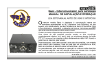
1332A REGULATED DC POWER SUPPLY Instruction Manual GL OB AL SPECIAL TIES GLOB OBAL SPECIALTIES M-00149 EDITION : 2- JULY, 2001 Global Specialties,LLC 22820 Savi Ranch Parkway Yorba linda,CA 92887 WWW.globalspecialties.com 800-572-1028 PCB Components Z-TR/01 PCB REV - 01 ======================================================================= Ref Designator Value ======================================================================= RESISTORS R1 1K,2W,5%,MOR R2 0.1E,2.5W,5%,WW R129* 33K,0.25W,5%,MFR CAPACITORS C1 C2 C3 0.1uF,50V,CD 100uF,50V,EL 10uF,50V,EL DIODE CR1 1N5402 X 2 PCB Components CHASSIS & FRONT PANELS ======================================================================= Ref Designator Value ======================================================================= TABLE OF CONTENTS GENERAL INFORMATION............................ Page 1 SPECIFICATIONS......................................... Page 2 LOCATION AND DESCRIPTION OF OPERATING CONTROLS.............................. Page 4 INSTALLATION.............................................. Page 5 OPERATING INSTRUCTIONS....................... Page 6 POWER SUPPLY OPERATION .................... Page 8 CHASSIS SAFETY INSTRUCTION ............................... Page 9 VARISTOR FOR 115V - 201K FOR 230V - DNR 20D 361 FILTER YUNPEN EMI 6A/125V/250V MAINS TRANSFORMER 650VA INPUT FUSE FOR 115V - 5Amp TYPE T FOR 230V - 2.5Amp TYPE T OPERATING PRECAUTIONS........................ Page 10 FRONT PANEL SERVICE AND WARRANTY INFORMATION. Page 12 WW POT WW POT WW POT 1KE 1W X 2 10KE 1W 50E 1W LED GREEN LED RED 3mm 3mm ON/OFF SWITCH DPST CHILLY 3022 6A /125V/250V CASE DISASSEMBLY AND ASSEMBLY....... Page 11 MAINTENANCE AND RECALIBRATION........ Page 11 PART LIST.................................................... Page 13 SCHEMATIC AND BOARD LAYOUT.............. Page 20 LIST OF ILLUSTRATIONS FIGURE 1. Location of operating controls...... Page 4 19 GENERAL INFORMATION DESCRIPTION The 1332A Power Supply is a high perfomance single output DC power supply for industrial and laboratory use. Performance with economy have successfully been combined to provide a compact, fully solid state instrument. The output is continuously variable from 0 to 32V and can supply 5A max, and can be adjusted continuously throughout the output range. The front panel CURRENT control can be used to establish the output current limit (overload or short circuit). When the supply is used as a constant voltage source the VOLTAGE controls can be used to limit the output voltage. When the unit is used as a constant current source, CURRENT controls can be used to limit the output current. The unit will automatically cross over from constant voltage to current mode and vice-versa, if the output current or voltage exceeds these preset limits. Output voltage and current are continuously monitored on two front panel meters. The load terminals are provided on the front panel. Either the positive or negative output terminal may be grounded or the power supply can be operated floating at upto a maximum of ±300VDC above ground. All the outputs are floating i.e. neither the output positive terminal nor the negative terminal (nor any point within the regulator circuitry) is connected to ground. The power supply is designed to operate in ambient temperature of upto 40°C and full output may be drawn continuously provided free air circulation is allowed.The unit works from mains supply of 115V/230VAC, 47-63 Hz with selectable Switch. 1 PCB Components 2 X Z-DPM/01 PCB REV - 01 ======================================================================= Ref Designator Value ======================================================================= RESISTORS R1 39K,0.25,5%,MFR R2 470K,0.25W,5%,MFR R3 1M,0.25W,5%,MFR R4* SEL(INPUT) R5 10K,0.25W,5%,MFR R6 2K4,0.25W,5%,MFR R7 330E,0.25W,5%,MFR R8 330E,0.25W,5%,MFR R9 6K8, 0.25W,5%,MFR PRESETS PR1 CAPACITORS C1 C2 C3 C4 C5 C6 C7 C8 C9 C10 220pF,50V,CD 0.1uF,100V,MP 0.01uF,50V,CD 0.47uF,100V,MP 0.1uF,100V,MP 0.1uF,100V,MP 10uF,50V,EL 0.1uF,50V,CD 10uF,50V,EL 0.1uF,50V,CD IC’s IC1 VR1 7107 DECODER DRIVER TL - 431 FND’s DS1 DS2 DS3 LED’s LED1* LED2* MISCILLANEOUS J1 J2 J3 2.5K,LIN,VER (REF ADJ) TSD566 GREEN TSD566 GREEN TSD566 GREEN 3MM GREEN(VOLTAGE) FOR 'CV' MODE 3MM RED (CURRENT) FOR 'CC' MODE 2.54PITCH,3PIN M NOT USED. 2.54PITCH,4PIN M 18 PCB Components ZSDT-CT/05 PCB ======================================================================= Ref Designator Value ======================================================================= ZENERS Z1 1N758, 10V, 0.4W Z2 1N758, 10V, 0.4W Z3 1N750, 4.7V, 0.4W BRIDGE BR1 BR2 10A/600V PC MTG BRIDGE CSB-1, 100V/1A BRIDGE. ICs IC1 IC2 IC3 IC4 IC5 IC6 IC7 IC8 4N25 OPTO 7812 TL431 LM324 7812 TL431 79L05 7805 Detailed specifications of the power supply are given in the following table. OUTPUT VOLTAGE LOAD CURRENT TRANSISTORS/FET/SCR Q1 BC109 Q2 MPSA12 Q3 BC557 Q4 BC557 Q5 BC547 FET1 IRFP150 SCR1 2N6396 FET2 IRFP150 CONNECTORS CON2 2.54mm PITCH, 12PIN M CON3 2.54mm PITCH, 12PIN M L TYPE CON4 2.54mm PITCH, 8PIN M MISCELLANEOUS TP1 TP2 TP3 TP4 TP5 TP6 SPADE CON SPECIFICATIONS RIM PIN RIM PIN RIM PIN RIM PIN RIM PIN RIM PIN 12H750 17 MALE MALE MALE MALE MALE MALE : 0-32V DC continuously variable with coarse and fine voltage controls : 0-5 Amp max., continuously variable with coarse and fine controls CONSTANT VOLTAGE MODE REGULATION LINE : Less than ± 0.01% +2mV for ±10% change in line voltage. LOAD : Less than ± 0.01% + 2mV for load change from zero to full load. RIPPLE & NOISE : Less than 1mV rms max. ( 20Hz - 20MHz ) CONSTANT CURRENT MODE REGULATION LINE LOAD RIPPLE & NOISE OUTPUT POLARITY OVERLOAD PROTECTION : Less than ± 0.1% +250µA for ±10% change in line voltage. : Less than ±0.1% +250µA for change in output voltage from 0 volts to max.output voltage. : 0.04% rms.(2.0 mA ) : Floating w.r.t. ground. : Automatic overload and short circuit protection. : 100µsecs to within 10mV of set output voltage for load change from 10% to 90%. TRANSIENT RESPONSE 2 STABILITY Total drift within 8 hours, after warm up under : ±0.1% +2.5mV in constant voltage mode. : ±0.5% +2mA in constant current mode. constant line,load & temp. PANEL METERS : Digital panel meters (marked V for voltmeter and A for ammeter) are provided with an accuracy of ± 3 counts. MODE INDICATION : Respective LED lights up when the unit is working in CV or CC mode. OUTPUT CONTROLS : Single turn coarse and fine voltage and current controls are provided on the front panel OPERATING TEMP. : 0-40°C. INPUT VOLTAGE : 115V / 230V AC, ± 10%, 47 - 63Hz single phase DIMENSIONS ( W x D x H ) : 230mm x255mm x133mm WEIGHT : 3 9.0Kg. nett. Approx. PCB Components ZSDT-CT/05 PCB ======================================================================= Ref Designator Value ======================================================================== C20 220µF/50V, ELE C21 47µF/50V, ELE C22 10µF/50V, ELE C23 0.1µF/50V, CD C24 10µF/50V, ELE C25 10µF/50V, ELE C26 0.1µF/50V, CD C27 470µF/50V, ELE C29 1000µF/35V,ELE DIODES CR1 CR2 CR3 CR4 CR5 CR6 CR7 CR8 CR9 C10 CR11 CR12 CR13 CR14 CR15 CR16 CR17 CR18 CR19 CR20 CR21 CR22 CR23 CR24 CR25 CR26 CR27 CR28 CR29 CR30 Not Used 1N4007, 1KV/1A 1N4007, 1KV/1A 1N4007, 1KV/1A 1N4007, 1KV/1A 1N4007, 1KV/1A 1N4007, 1KV/1A 1N4007, 1KV/1A 1N4007, 1KV/1A 1N4007, 1KV/1A 1N4007, 1KV/1A 1N4007,1KV/1A. 1N4007,1KV/1A. 1N4007,1KV/1A 1N4007,1KV/1A 1N4007, 1KV/1A 1N4007, 1KV/1A 1N4007, 1KV/1A 1N4007, 1KV/1A 1N4007, 1KV/1A 1N4007, 1KV/1A 1N4007, 1KV/1A 1N4007, 1KV/1A 1N4007, 1KV/1A 1N4148, 100V/10mA 1N4148, 100V/10mA 1N4148, 100V/10mA 1N4148, 100V/10mA 1N4007, 1KV/1A 1N4007, 1KV/1A 16 PCB Components ZSDT-CT/05 PCB ======================================================================= Ref Designator Value ======================================================================== R37 2K, MFR, 1/4W, 5% R38 1K, MFR, 1/4W, 5% R39 1K, MFR, 1/4W, 5% R40 4.7K, MFR, 1/4W, 5% R41 330K, MFR, 1/4W, 5% R42 100E, MFR, 1/4W, 5% (I CAL) R43* 3.9K, MFR, 1/4W, 5% (I CAL) R44 1K, MFR, 1/4W, 5% R45 1K, MFR, 1/4W, 5% R46* 10K, MFR, 1/4W, 5% (V CAL) R47* 100E, MFR, 1/4W, 5% (V CAL) R48 2K, MFR, 1/4W, 5% R49 Shorting Link R50 Shorting Link R51 10E, MFR, 1/4W, 5% R59 10E, MOR, 2W PRESETS PR101 PR102 PR103 CAPACITORS C1 C2 C3 C4 C5 C6 C7 C8 C9 C10 C11 C12 C13 C14 C15 C16 C17 C18 C19 LOCATION AND DESCRIPTION OF OPERATING CONTROLS In order to use the full capabilities of the 1332A, it is highly recomended that the user become familiar with the controls associated with this instrument. (See Figure 1) Figure 1. Location of operating controls. 5K, PRE, LIN, (V)(DEV. DROP) 500E, PRE, LIN, (V)(V CAL) 500E, PRE, LIN, (V)(I CAL) 0.1µF/100V, MP 0.1µF/250VAC MKP 15,000µF/50V ELE 0.1µF/50V, MP 10% 33µF/50V, ELE 100µF/50V, ELE 100µF/50V, ELE 1µF/50V, ELE 4.7µF/50V, ELE 10µF/50V, ELE 100µF/50V, ELE 47µF/50V, ELE 1kpF/50V, CD 1kpF/50V,.CD 0.1µF/50V, CD 10µF/50V, ELE 10µF/50V, ELE 0.1µF/50V, CD 220µF/50V, ELE 15 1-Power ON/OFF switch. 7-Current Fine Control Clockwise rotation increases variable output current in CC mode. 2-Supply LED Display. 8-CV LED Display Voltage 0 to 32VDC Constant Voltage mode Indication 3-Supply LED Display. 9-CC LED Displays current 0 to 5AMP. Constant Current Mode Indication 4-Variable coarse voltage control. 10-Output terminals Clockwise rotation increases Red terminal is output (+)ve. variable o/p voltage in CV mode. Black terminal is output (-)ve. 5-Variable fine voltage control. 11-Ground terminal. Clockwise rotation increases variable output voltage in CV mode. 6-Current coarse Control. Clockwise rotation increases variable output current in CC mode. 4 INSTALLATION INITIAL INSPECTION : As soon as the power supply unit is unpacked inspect for any damage that may have occured during transit. Save all packing material until inspection is completed. If any damage is found, notify the carriers immediately. Our authorised representatives should also be notified. PHYSICAL CHECK : This check should confirm that there are no broken knobs or connectors, that the cabinet and panel surfaces are free of dents and scratches and the meters are not scratched and cracked. ELECTRICAL CHECK : The power supply unit should be checked against electrical specifications.An in-cabinet performance check will verify proper operation. INSTALLATION DATA : The power supply unit is shipped ready for bench operation. It is necessary only to connect the unit to a rated source of power and it is ready for operation. LOCATION : The power supply unit is naturally cooled.Sufficient space should be kept around the unit while in operation, so that heat sinks do not remain in confined space or close to another heating source.The ambient temperature of the area around the unit should be less than 40°C. INPUT POWER REQUIREMENTS : The power supply unit may be operated continuously from input voltage of 115V / 230V 47-63Hz power source with selectable Switch. REPACKAGING FOR SHIPMENT : To ensure safe shipment of the power supply unit, it is recommended that the package designed for the unit be used. The original packaging material is reusable. Be sure to attach a tag to the unit specifying the owner, and the fault observed with a brief description. REMOVING COVER : The top cover is retained in place by 6 self tapping screws & two handle mounting screws. To remove cover, proceed as follows : a) Remove the handle mounting screws. b) Remove the self tapping screws on sides. c) Lift the cover from rear side, slide backwards & pull. 5 PCB Components ZSDT-CT/05 PCB ======================================================================= Ref Designator Value ======================================================================== R37 2K, MFR, 1/4W, 5% R38 1K, MFR, 1/4W, 5% R39 1K, MFR, 1/4W, 5% R40 4.7K, MFR, 1/4W, 5% R41 330K, MFR, 1/4W, 5% R42 100E, MFR, 1/4W, 5% (I CAL) R43* 3.9K, MFR, 1/4W, 5% (I CAL) R44 1K, MFR, 1/4W, 5% R45 1K, MFR, 1/4W, 5% R46* 10K, MFR, 1/4W, 5% (V CAL) R47* 100E, MFR, 1/4W, 5% (V CAL) R48 2K, MFR, 1/4W, 5% R49 Shorting Link R50 Shorting Link R51 10E, MFR, 1/4W, 5% R59 10E, MOR, 2W PRESETS PR101 PR102 PR103 CAPACITORS C1 C2 C3 C4 C5 C6 C7 C8 C9 C10 C11 C12 C13 C14 C15 C16 C17 C18 C19 5K, PRE, LIN, (V)(DEV. DROP) 500E, PRE, LIN, (V)(V CAL) 500E, PRE, LIN, (V)(I CAL) 0.1µF/100V, MP 0.1µF/250VAC MKP 15,000µF/50V ELE 0.1µF/50V, MP 10% 33µF/50V, ELE 100µF/50V, ELE 100µF/50V, ELE 1µF/50V, ELE 4.7µF/50V, ELE 10µF/50V, ELE 100µF/50V, ELE 47µF/50V, ELE 1kpF/50V, CD 1kpF/50V,.CD 0.1µF/50V, CD 10µF/50V, ELE 10µF/50V, ELE 0.1µF/50V, CD 220µF/50V, ELE 14 SECTION 5 PART LIST & SCHEMATICS PCB Components ZSDT-CT/05 PCB ======================================================================= Ref Designator Value ======================================================================== RESISTORS R1 R2 R3 R4* R5 R6 R7 R8 R9 R10 R11 R12 R13 R14 R15 R16 R17 R18 R19 R20 R21 R22 R23# R24 R25 R26 R27# R28# R29# R30 R31 R32 R33 R34 R35 R36 270E, 2W, 5%, MOR 47E, MFR, 1/4W, 5% 10K, MFR, 1/4W 1K, MFR, 1/4W, 5% 10E, MFR, 1/4W, 5% 3.9K, MFR, 1/4W 3.3K, 2W, 5%, MOR 10K, MFR, 1/4W 8.2K, MFR, 1/4W 100K, MFR, 1/4W 4.7E, MFR, 1/4W. 1.5K, MFR, 1/4W. 180K, MFR, 1/4W. 390E, MFR, 1/4W. 6.8K, MFR, 1/4W, 5% 12K, MFR, 1/4W, 5% 3.9K, MFR, 1/4W, 5% 10K, MFR, 1/4W 10K, MFR, 1/4W 10K, MFR, 1/4W 3.3K, 2W, 5%, MOR 270E, 2W, 5%, MOR 82K, MFR, 1/4W, 5% 4.7K, MFR, 1/4W, 5% 24E, MFR, 1/4W, 5% 820E, MFR, 1/4W, 5% 330K, MFR, 1/4W, 5% 39K, MFR, 1/4W, 5% 180K, MFR, 1/4W, 5% 1K, MFR, 1/4W, 5% 15E, MFR, 1/4W, 5% 6.8K, MFR, 1/4W, 5% 15K, MFR, 1/4W, 5% 6.8K, MFR, 1/4W, 5% 15K, MFR, 1/4W, 5% 1K, MFR, 1/4W, 5% 13 OPERATING INSTRUCTIONS TURN ON SETTING PROCEDURE The following procedure describes the use of controls and indicators. a. Ensure that the AC power switch is in the "OFF" position. b. Connect the unit to a specified input voltage. c. Turn the VOLTAGE and CURRENT controls fully counter-clockwise. d. Set ‘POWER ON’ Switch to "ON" position,The front panel digital meters will light up and voltmter and ammeter displays will read zero,and observe that CV LED glows. e. Adjust the ”VOLTAGE” controls till the desired voltage is indicated on voltmeter. f. To check "CONSTANT CURRENT" mode, turn OFF the supply. Short circuit the output terminals of the power supply and turn ON the supply. g. Adjust 'CURRENT' controls until the desired out put current is indicated on ammeter. Also check that the CC LED glows. h. Remove the short circuit. CONSTANT VOLTAGE MODE : To select a constant voltage output, proceed as follows : a. Connect a digital voltmeter (DVM) across the out put terminals, observing correct polarity. The DVM must be rated for better than 0.5% accuracy. b. Turn the CURRENT controls clockwise. And Slowly If a load change causes the current limit to be exceeded, the power supply will automati cally cross over to constant current output at cur rent limit and output voltage will drop proportion ately. In setting the current limit, allowance must be made for high peak currents which can cause unwanted crossover. 6 CONSTANT CURRENT MODE : To select a constant current output, proceed as follows : a. Short circuit the output terminals of the power supply. b. Connect a DC Ammeter OR a shunt-digital voltmeter (DVM) combination across the output terminals, using appropriately-guaged wire and hardware. The recommended current ratings for the ammeter or he shunt and the wire must be at least 10% more than the output current of the power supply model. The ammeter or shunt-DVM combination must be rated better than 0.5% accuracy. c. Turn the VOLTAGE controls clockwise. And Turn the CURRENT controls slowly clockwise. The CURRENT control range will be from minimum to maximum rated output current. Adjust CURRENT controls for desired output current. d. Compare the ammeter reading with the front panel ammeter reading. Or, compare the DVM reading with the front panel ammeter reading using I = V/R, where V is the DVM reading and R is the DC shunt resistance. e. Open output terminals and adjust VOLTAGE controls for maximum output as required by the load conditions. If a load change causes the voltage limit to be exceeded, the power supply will automatically cross over to constant voltage output at the preset voltage limit and output current will drop proportionately. In setting voltage limit, allowance must be made for high peak voltages which can cause unwanted crossover. Turn the VOLTAGE controls clockwise and observe both the front panel voltmeter and the DVM. Compare the DVM reading with the front panel voltmeter reading to verify the accuracy of the internal voltmeter c. The VOLTAGE control range will be from minimum to the maximum rated output voltage. Adjust desired voltage by adjusting the voltage controls. d. Short circuit output terminals and adjust CURRENT controls for maximum output current as required by the load conditions. 7 SERVICE AND WARRANTY INFORMATION FACTORY SERVICE AND REPAIR : Global Specialties will service and repair this instrument free of charge for a period of one full year subject to the warranty conditions stated below. To obtain a return merchandise authorisation (RMA) required for all returns, phone our customer service department for a RMA and all shipping instructions : GLOBAL SPECIALTIES 70 Fulton Terrace, New Haven, Connecticut 06512, TEL.: (203) 466 – 6103 FAX : (203) 468 – 0060 Email : [email protected] ATTN : Customer Service Department WARRANTY Global Specialties warrants this device to be free from defective material or workmanship for a period of 3 years from the date of original purchase. Global Specialties under this warranty is limited to repairing the defective device when returned to the factory,shipping charges prepaid, within three full years from the date of original purchase. Units returned to Global Specialties that have been subject to abuse, misuse, damage or accident or have been connected, installed or adjusted contrary to the instructions furnished by Global Specialties, or that have been repaired by unauthorised persons will not be covered by this warranty. Global Specialties reserves the right to discontinue models, change specifications ,price or design of this device at any time without incurring any obligation whatsoever. The purchaser agrees to assume all liabilities for any damages and/or bodily injury which may result from the use or misuse of this device by the purchaser his employees or agents. This warranty is in lieu of all other representations or warranties expressed implied and no agent or representitive of Global Specialties is authorised to assume any other obligation in connection with the sale and purchase of this device. 12 CASE DISASSEMBLY AND ASSEMBLY WARNING Potentially lethal AC power is present whenever theline cord is plugged into the AC outlet,even when the power switch is OFF. Always disconnect the power cord when opening the case. Avoid touching the fuse post on the inside of the unit. Should access to the inside of the unit be required, proceed as follows 1. Remove the line cord from the AC outlet before disassembly 2. To disassemble the case,remove the screws that secure the cover to the chassis and lift the cover off. 3. To reassemble the case, place the cover on the chassis, line up the screw holes, and replace the screws. MAINTENANCE AND RECALIBRATION ADJUSTMENTS : All circuitry is factory -calibrated. No user adjustments are required. FUSE REPLACEMENT : Remove the line cord from the AC outlet before changing fuses. Using the screwdriver, remove the fuse holder cap. Replace the fuse with another of identical type and current rating. Replace the fuse holder cap. 11 If a load change causes the current limit to be exceeded, the power supply will automatically cross over to constant current output at current limit and output voltage will drop proportionately. In setting the current limit, allowance must be made for high peak currents which can cause unwanted crossover. CONSTANT CURRENT MODE : To select a constant current output, proceed as follows : a. Short circuit the output terminals of the power supply. b. Connect a DC Ammeter OR a shunt-digital voltmeter (DVM) combination across the output terminals, ing appropriately-guaged wire and hardware. The recommended current ratings for the ammeter or the shunt and the wire must be at least 10% more than the output current of the power supply model. The ammeter or shunt-DVM combination must be rated better than 0.5% accuracy. c. Turn the VOLTAGE controls clockwise. And Turn the CURRENT controls slowly clockwise. The CURRENT control range will be from minimum to maximum rated output current. Adjust CURRENT controls for desired output current. d. Compare the ammeter reading with the front panel ammeter reading. Or, compare the DVM reading with the front panel ammeter reading using I = V/R, where V is the DVM reading and R is the DC shunt sistance. e. Open output terminals and adjust VOLTAGE controls for maximum output as required by the load conditions. If a load change causes the voltage limit to be exceeded, the power supply will automatically cross over to constant voltage output at the preset voltage limit and output current will drop proportionately. In setting voltage limit, allowance must be made for high peak voltages which can cause unwanted crossover. 8 LOAD CONNECTIONS : OPERATING PRECAUTIONS The load should be connected to the power supply output terminals using separate pairs of connecting wires. This will minimize mutual coupling effects between loads and will retain full advantage of the low output impedance of the power supply. Each pair of connecting wires should be as short as possible and twisted or shielded to reduce noise pick up. (If a shielded pair is used, connect one end of the shield to ground at power supply and leave the other end unconnected). Positive or negative voltage can be obtained from this supply by grounding either one of the output terminals or one end of the load. Always use two leads to connect load to the supply, regardless of where the set up is grounded. This will eliminate any possibility of the output current return paths through the power source ground which would damage the line cord plug. This supply can also be operated upto ±300V DC above ground, if neither output terminal is grounded. POWER SUPPLY OPERATION INITIAL SET UP : Refer to the preceding section for initial set up of the power supply. OPERATING INSTRUCTIONS : Proper operation of most circuitry depends on correct supply voltages. It is recommended that the power supply be set to the required voltage levels with the load disconnected. When the desired voltage is set (using the variable voltage control),turn the AC power OFF, connect the load to the power supply. then turn the AC power ON. Output voltage and current of the power supply may be read on the separate digital panel meters continuously. 9 The power supply is ideally suited for virtually any type of IC bread boarding from TTL, CMOS and ECL to op-amps, audio and video amps, phase locked loops, and microprocessor circuitry. However,certain normal bread boarding precautions should be taken to avoid ground loops and inadvertent loading. Observance of correct load polarity is also important since most ICs may be damaged by improper power supply connections. POLARITY : Observe proper polarity when connecting the power supplies to the load, especially if the load is polarity sensitive and does not have reverse polarity protection. GROUND LOOPS : A ground loop is a voltage drop on a ground bus caused by a power stage output entering the ground bus some distance away from the power supply ground binding post. This small voltage drop, though only milliVolts or micro Volts, is a part of the output load. If a preamplifier input of circuit ground is connected to a portion of this ground bus, feedback and oscillation may occur. To prevent this all output stages should be positioned as close as possible to the ground terminal,preamps farther away. Many audio IC's have seperate input and output grounds to prevent ground loops. Eventhough power supplies are tightly regulated, a short length of a power bus can present enough inductance to cause linear IC oscillation at high frequencies. For this reason, effective bypass capacitors are needed to bypass the power buses. Place these capacitors as close as possible to the power supply pins of the IC.Disc ceramics (0.1µF ) work well and should be placed across as many ICs as possible. Do not use elec trolytic or paper capacitors because they have high inductances and cease to act as bypasses above one or two MHz. Bypassing is required with digital IC's also; problems such as inability to reset or to clear and false triggering can occur if IC's are not properly bypassed. 10