1
USER’S MANUAL
Automotive Diagnostic Scanner
ATTENTION: VERY IMPORTANT
In this manual you will find the answers to all your questions. Read it carefully
Language: English
Version software: V2007-1
Manual Version: 2-Feb-07
1 of 34
INDEX
Recommendations-Warnings
Introduction
* Main Functions
General Features
* Use of SPCMAX
* Computer minimum requirements
* SPCMAX vehicle connection
SPCMAX
Presentation
* Component list
Installation
* Connection diagram
* Leds Code
* Software installation
How to use
* First Screen
* Configure
* Tester
* Introduction to Customer Database
* Language seleccion
* Upgrade (Via Internet)
* Uninstall
* Date and Time
Model and System Selection (Second Screen)
* Make code and systems available
* Selection by system
* Selection by model
* Back
Connection to the vehicle (Third Screen)
* Diagnostic connector location
* Connection to diagnostic connector - Doubts and risks
* Pin-Out (Connections)
* Measurements (Live Data)
* Special mode: VW Live data
Fault Reading (Forth Screen)
* General aspects
* Basic adjustment or Autoadaptation
* Actuators test
* Dynamic test
* Faults memory erasure
Data base
* Access to database
* How to use the database
2 of 34
4
5
5
5
5
5
6-7
7
7-8
8
8-9
9
9-10
10
10
11
11
12
12
12
13
13
14
14
14
14
15
15
15
15
16
16
17
18
18
18
18
18
19
19
19
20-25
Data Printing
* Incompatible printers
Trouble code reading through OBDII screen
Reset service screen
Voltmeter
* Description
* Warnings
Oscilloscope
* Description
* Warnings
Special functions
* Manual adjustment Marelli 1AVB/1AVS/1AVP (VW)
Bluetooth
* Problems with interferences
* Special warning
Specifications
* General SPCMAX specifications
* 2 Channel Digital oscilloscope
* Voltmeter
Regulatory Information – Declaration of Conformity
3 of 34
25
25
26
26
27
27
28
28
28
29
30
30
30
30
30
31
31
31
32
33
Recommendations - Warnings
1.
2.
3.
4.
5.
Verify that your workshop electrical system has cable to ground. (Mass)
DO NOT connect or disconnect USB port with PC on.
Turn off the screensaver and the antivirus. These features may cause communication errors or Windows errors.
DO NOT run any program while using the SPCMAX.
Keys and menues with letters colored in LIGHT GREY ARE NOT available, while the ones colored DARK GREY
are available.
6. WARNING / CAUTION: Seat-belt pretensioners annulment
If you annul one or more seat-belt pretensioners we recommend taking into account the following items:
a) The annulment of one or more seat-belt pretensioners implies that they will not work in case of accident
(connected or not). The fault light will remain off, SHOWING THAT ALL THE SYSTEM IS WORKING PROPERLY.
b) Warn and explain to the vehicle owner the effects of the system reconfiguration he is requiring.
c) DEMAND AND FILE AN ORDER SIGNED BY THE VEHICLE OWNER, giving you the order and authority to
change airbag’s original configuration.
d) Once the system has been reconfigured, make a fault reading confirming that the new configuration is the one
ordered and authorized by the vehicle owner. This is displayed on the top right side of the fault screen.
(Superimposed on the red panel)
e) If you want, you can print a form with the order and authorization to be filled and signed by the vehicle owner.
EXPLAIN TO THE VEHICLE OWNER THE RISKS OF FOLLOWING THIS PROCEDURE.
"HAVING NO CONTROL OVER THE OPERATOR PERFORMING THE RECONFIGURATION, THE SCANNER
MANUFACTURING COMPANY, ITS REPRESENTATIVES AND DISTRIBUTORS, DO NOT TAKE ANY
RESPONSIBILITY FOR THE CONSEQUENCES THAT MAY RESULT FROM THE IMPROPER USE OF THIS
PROCESS."
IMPORTANT: When feeding scanner always connect negative (black banana) first. If you
disconnect scanner leave the negative for the end.
If you remove negative first, mass could be done through other cables. (Green or yellow). This
will cause the scanner to burn and will have to replace internal plates.
If the computer has losses of energy or you feed scanner with a battery charger which has a
cable in common with a 220V feeding remember to follow these instructions, if not there is a
serious risk to burn the interphase.
4 of 34
INTRODUCTION
SPCMAX princippal functions
1. Location and actual diagram of the Diagnosis Input Socket (connector) for loaded systems.
2. Fault reading: By Data flow.
3. N/A
4. Fault memory erasure.
5. By Data Flow, shows in reaal time the sensor values being processed by the different ECU (Electronic Control
Unit).
6. Allows to correct the Ignition Advance, RPM or richness (when the ECU allows it).
7. Allows to perform the Autoadaptation (when the ECU allows it)
8. Ford EEC IV: make the KOEO and KOER tests.
9. Actuators Test and/or Basic Adjustment (when the ECU allows it).
10. Reading in: ABS - Airbag - Climatization - Automatic Gear - Body - 4WD - CAN (see makes enabled).
11. Instrument Panel: Reset Service, diagnosis, actuators. (see makes enabled).
12. Inmovilizer: Faults, recoding and keys synchronization (see makes enabled).
13. CARB OBD II: fault reading in OBD. Generic. Different systems: Injection, ABS, etc.
14. OBD II: per Make protocol, Sensors - Frozen and Lambda value reading - Memory erasure.
15. Pin-Out: shows the connection of each pin of selected ECU.
16. Help: offers generic information about the different injection systems.
17. Data base: Incorporate customers and vehicle data, including fault reading and live data.
18. Measurements graph: Allows to perform the road test, showing the evolution of the values measured by sensors.
(Up to 4 grpahics at the same time)
19. Reference range: indicates the range in which the values should be found under normal conditions.
GENERAL FEATURES
The SPCMAX is a scanner specially designed to read the fault memory of different vehicles Electronic Control Unit (ECU).
Detection of these faults depends on the vehicle and the system it has on SPCMAX. SPCMAX only performs the reading
and interpretation of the data.
Equipment includes: PROGRAM, INTERFACE, CONNECTION CABLES and BAG.
Computer minimum requirements
Pentium IV 1.4 Ghz with:
• 256 MB RAM
• 2 Gb Hard disk
• CD-ROM
• Windows XP
• 1 USB 2.0 port.
Connections
The SPCMAX is connected to all vehicles through 1, 2 or 3 terminals (yellow, green and and/or blue) to DLC (Data Link
connector) The red and black terminals are connected to the positive (+) and negative (-) of the vehicle to be tested.
5 of 34
Next you will find the different ways to connect SPCMAX to vehicle:
Pins for diagnostic connectors:
For those vehicles without OBDII connector, SPCMAX includes connection pins. Next you will find a make reference to
know which pin to use for which make.
NOTE: These are referencial indications. Pins may be used for more makes than indicated. The vehicle connectors may
present changes not known by Condistelec.
1.
2.
3.
4.
5.
6.
7.
8.
9.
Old Ford / Old VW / Chrysler 6 Pin
Alfa Romeo / Fiat 3 Pin / Nissan / OBDII
BMW
Daihatsu / Mitsubishi / Peugeot 30 pin
Peugeot 2 pin / GM 12 pin / GM 10 pin
Rover 3 pin
MB 14 pin
MB 38 pin
Renault
6 of 34
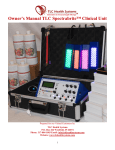
SPCMAX PRESENTATION
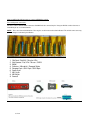
Component List
Item #
Qty
1
1
1
1
1
1
1
1
1
1
1
1
1
1
1
1
2
3
4
5
6
7
8
9
10
11
12
13
14
15
16
7 of 34
Code
Description
SMAX
SOFTCD
MALE
CLAR
CRCA
CENC
CCOC
C5PU
CUSB
CRCAWH
CRCABL
CMAOSC
FOBD
PVA
CBAL
KBLU
SPC MAX Interfase
CD Software
Bag
Long cable (5mts)
RCA M-M cable
Cigarlighter cable
Crocodille cable
5 end cable
USB 2.0 cable
RCA Cable white for oscilloscope
RCA Cable blue for oscilloscope
Mass Cable for oscilloscope
OBDII connector
19 pins Green/Yellow
Power supply cable
Bluetooth dongle (OPTIONAL)
List subject to change according to version our country. Subject to changes without notice.
INSTALLATION
SPCMAX CONNECTION DIAGRAM
PC connection side
1. ECU Connection Led
2. PC Connection Led
3. RS232 (PC Connection)
4. USB (PC Connection)
5. Bluetooth (wireless connection to PC)(Optional)
8 of 34
Vehicle connection and power supply side
1.
2.
3.
4.
5.
6.
Automatic pin selection Led
Power supply Led
Oscilloscope Channel 1
Oscilloscope Channel 2
Connection to vehicle
Power supply Jack - 9 to 50 V/DC
ATTENTION: in order to iniciate software, SPCMAX has to be connected to PC. There are 3 possible ways: RS232
(Serial), USB or Bluetooth (optional). Keep in mind it only connects through one of them at a time.
Leds code:
Code
Power
(Red)
Description
Power supply
Led operation
On: interface power on
Off: interface power off
Pin search Automatic pin selection
(Blue)
Slow flashing: Stand by
Fast flashing: pin selection
ECU
(Yellow)
ECU Connection
Slow flashing: Stand by
On: dialog between MAX and ECU
PC
(Green)
PC Connection
Slow flashing: no connection to PC
On or Off: Stand by
Fast flashing: dialog with PC
ATTENTION:When connecting USB, the red led will be slightly on.
However, it does not mean the power is on. It means interface is connected to USB
Bip:
Interfase bips when software dialogs with it.
SPCMAX SOFTWARE INSTALLATION
Turn on the PC (computer).
1. Insert the CD.
9 of 34
2. A screen will automatically open, double click on “INSTALL”.
3. If the screen does not open, go to Start, Execute and write "X:\INSTALL", where "X" is the letter belonging to the CDrom Drive (usually "D").
4. If a message reads: "An access violation has occurred when copying the file", click on "Omit" and the installation will
go on (it happens when there are different versions of some windows libraries).
5. To operate the SPCMAX program in Windows, click on the SPCMAX icon in your desktop.
INCOMPATIBILITIES
• There can not be ANY OTHER PROGRAM IN MEMORY OR IN EXECUTION in the P.C.(computer) (for example Office,
etc.)
• If there are any programs loaded when Windows starts, they must be CLOSED BEFORE STARTING SPCMAX
software.
• In Notebooks battery charge control program MUST NOT be working.
TO PREVENT DIFFICULTIES, FOLLOW THE MENTIONED RECOMMENDATIONS
PROBLEMS DURING THE INSTALLATION.
If for any reason an incovenience occurs during installation: Reset computer and start again. If it happens again, note down
the problem, go to www.SPCMAX.com and fill "Technical Support" form.
Remember: SPCMAX interface must be connected to PC and power on (from 9 to 50V) for the program to run.
If the interfase is not connect to power supply, software WILL NOT RUN.
HOW TO USE
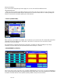
SPCMAX – FIRST SCREEN
Figure 2 - First Screen "SPCMAX"
In this screen you will find: "Name", "Garage data" (name-address-phone) and "Date and time", which are directly read
from the PC (computer).
Serial number of the scanner, is showed in the middle right of the screen in yellow.
In this example, the number is: MEC0001AR
10 of 34
Is very important to know your scanner number because it will be required to give you technical support.
"SCANNER”: To start using SPCMAX, click on “SCANNER”
“OSCILLOSCOPE”: button to access Oscilloscope function. (For more information, go to page 28)
“VOLTMETER”: button to access Voltmeter function. (For more information, go to page 27)
OPTIONS AVAILABLE ON THIS SCREEN:
» CONFIGURE
SPCMAX software configures automatically. Automatic configuration will work in most PCs. If not, port number can be
changed using the Configure menu. Once configured, the options are saved.
AUTOCONFIGURATION
In "Configure" menu you can perfom "AUTOCONFIGURATION", which normally performs the correct configuration. If
necessary, you may do a manual configuration.
MANUAL CONFIGURATION
Go to "CONFIGURE" and then the option "CONFIGURE" at the end of the list. A screen will open asking you to enter the
password; which is: "SPCMAX". After that you will be able to choose the Manual or Automatic configuration.
You must click the required option in the "CONFIGURE" menu list and will be automatically saved. If any other change is
required you must repeat all the operation."
HEARING SOUNDS: this function is enabled by default. This function allows the scanner to talk.
To disable this function: go to "CONFIGURE" and then the option "SOUNDS????" at the end of the list. A screen will open
asking you to enter the password: "SPCMAX".
Click on “HEARING SOUNDS”: The check will desapear, showing the scanner has this function disabled.
Remember: for the scanner to talk, your PC has to have soundcard and speakers (The speakers have to be connected to
power supply)
ATTENTION: WE RECOMMEND AUTOCONFIGURATION.
» TESTER
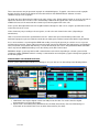
Figure 3 - Tester
The correct running of the TEST ensures that the system composed by: PC (computer), its configuration, interface and all
connections work properly.
On the First Screen ("SPCMAX"), between the "Configure" and "Database" options, the "TESTER" option allows you to
perform the SPCMAX working test. This test is explained in the program. (Read carefully the messages on screen). NO car
is needed to perform the test, only make the connections shown on screen and then start.
11 of 34
TROUBLE SHOOTING
• IF THE SELF-TEST IS OK BUT DOES NOT ALLOW TO ESTABLISH COMMUNICATIONS: verify mass and car
connections. If connected through the cigarlighter, check that carlighter is in optimal operating conditions.
• Any incorrect option avoid the correct functioning of SPCMAX
WARNING: SELF-TEST is automatically performed each time SPCMAX software starts. Only if the autotest did not end
properly the last time will be executed again.
» CUSTOMER DATABASE
Click on the DATABASE menu, choose VEHICLE FILE. Once you click on this option will show the VEHICLE FILE screen.
It will show: Workshop Data, Customer Data and Car Data.
To find a more detailed explanation, go to Data Base.
» LANGUAGE
Allows you to choose language from a list.
» UPGRADE
When entering this menu, the SPCMAX software will close automatically and open a new window.
When activating this function through the “Start Download” button, the program will connect to Internet (you may use a
wideband or a modem connection) and will try to download the last software version. If it is available, it will be downloaded
into the hard disk. Once the process ends, installation program will start automatically.
The installation is automatic, without user intervention. It stores the upgrade in the UPDATE folder, inside the folder where
the SPCMAX program is installed, allowing to repeat upgrade if necessary.
12 of 34
» DATE AND TIME
To change date or time in Windows, go to: My PC, Control Panel, click on Date and Time and Clock/Calendar will appear.
To change date and time format, go to: My PC, then to Control Panel, then to Regional Configuration.
If time of your PC (computer) delays or forwards, repair it to work properly. SPCMAX software uses these times to
operate.
13 of 34
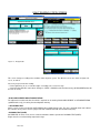
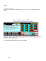
Model and System Selection – SECOND SCREEN
Figure 7 - System Selection
Figure 8 - Model Selection
On this screen you choose the vehicle according to Type of system or Year, Model and Engine.
Top right you will find the SYSTEMS and MODELS options. Click on the desired option.
• SYSTEMS: allows to select manually vehicle make and type of system (Injection-ABS-Airbag, etc) available.
• MODELS: allows to enter to Injection, Diesel, ABS or Airbag choosing: Make - Manufacturing year - Model - Engine
Code and KW.
» MAKES CODE AND SYSTEMS AVAILABLE (-) (+) (X) (*)
Systems available have the following signs on the right which indicates the available functions.
(-) Faults.
(I) Pin out
(+) Faults and Pin out.
( X ) Faults and Measurements. (Live data)
( * ) Faults, Pin out and Measurements. (Live data)
» SELECTION BY SYSTEM
On the top of the screen you will find different buttons with the types of systems available, click on them different systems.
(Injection, Diesel Abs, Airbarg, etc) Select a make from the VEHICLE BRAND list located on the left of the screen. It will
display systems for that vehicle brand and type of system in the list located on the right.
With some vehicle brands some buttons may appear below the systems list. These buttons allow autodetection of systems
according to make or type, depending on the case. This way the correct system will be automatically selected. Click on
these buttons to access autodetection mode. Third Screen will automatically be reached after performing autodetection.
ATTENTION: About Autodetection of systems marked with # : systems NOT marked with # cannot be detected, but
communication can be erroneously established due to its similitude with other systems. Verify the faults returned by the
system (on the Trouble Code Reading screen) are possible, if not, you must select another system without using
autodetection.
After selecting system, click on SCANNER to read the faults, measurements and make connection with ECU.
» SELECTION BY MODEL
Select manufacture year of the vehicle, model and finally engine.
After selecting this, click on SCANNER to go to connection screen.
14 of 34
» BACK
Click on BACK button to return to previous screen.
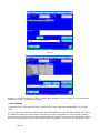
Connection to the Vehicle – THIRD SCREEN
Figure 10 - Connection in the Vehicle.
»DIAGNOSTIC CONNECTOR LOCATION
On the left side of the screen you may find: A car drawing and several car photos (depending on the make and model
selected), where the possible locations of the Diagnosis Connector are shown. The location depends on each particular
vehicle and may not apply to other models.
Click on any image to enlarge it. To return to the small image, click on it again.
The car image with two views specifies all possible locations of the diagnosis input switch connector. Image used is only an
example and applies to all the vehicles in the selected system.
Photos were taken from the vehicles specified below the image. They may or not apply to other models.
All the images and photos are property of SPC Group ® All rights reserved
»CONNECTION TO DIAGNOSTIC CONNECTOR - DOUBTS AND RISKS
On the right side of the third screen are shown skematic drawings of the diagnosis input switch connector. All possibilities
according make and selected systems are shown (you will use only one of these options). Position in which the two (2)
SPCMAX terminals (Green and Yellow) must be connected is shown on them. In the case of Nissan there will be 3
terminals: green, yellow and blue.
Several alternative connections can be distinguished. Connection marked by a red line is the most likely connection. If
there were no connectors in the connector or no communication could be established using the red line option, try one of
the other connections shown by blue lines.
In some cases only one of the terminals must be connected. If that is the case verify the other terminal is not connected to
mass.
Red and Black bananas must ALWAYS be connected to power supply (9 to 50 Volt). Through the carlighter adaptor or
15 of 34
directly on the battery.
If you connect power supply through “Power Supply Jack”, do not connected Red and Black bananas
TROUBLE SHOOTING
• Make sure you are using the proper Data Link Connector and of the same color (if shown on screen), because some
cars may have more than one similar connector. Remember some connector contacts have 12 V and may damage the
interface, if connected to connected to yellow, green or blue bananas.
» PIN-OUT (CONNECTIONS)
Figure 9 - ECU pin-out
When selecting a system with pin-out available, click on “Pin-Out” to access this function. This function will show the ECU
connections to each one of the sensors and actuators of the vehicle. To exit pin-out screen and return to Vehicle
Connection screen click on BACK.
Pin-out information is supplied by manufacturers. SPC Group - Condistelec has NO responsibility for any change,
modification or mistake about them. All responsibility about derived damages is excluded.
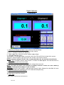
» MEASUREMENTS (LIVE DATA)
Figure 11- Real-time system measurements.
Figure 12 - Measurement Graphics
Click on ECU Values button on the third screen, (VEHICLE CONNECTION) or on the fourth screen (FAULT READING) to
access to measurements (live data) screen. Measurements are the values of the sensors and actuators procesed by ECU
in real time. Remember that if it is not in optimum operating condition, it may show non-real values.
16 of 34
These measurements may be presented on graphs for a detailed diagnose. To graphic, select items to make a graphic
through check box located on the right of the value able and then click GRAPHIC button. Software can make
simultaneously up to four (4) graphs.
The graph may be re-dimensioned in relation to the value or time scales. Pull the marker located on one of the axle ends to
adjuste it to desired scale. The value scale is automatically established if the typical values of the measurement are
available.It increases if the measured value cannot be presented in graphic form in the scale.
Some systems allow adjustment of the mix or ignition advance through Live data screen, using the special buttons located
on the lower side of the screen.
Values shown may vary according to selected system, as well as the units shown for the values. (Depending on
manufacturer)
Limits of each measurement are specified below each one. Yellow color represents minimum possible value, red
maximum.Light green represents minimum normal value and dark green maximum normal value with the engine IDLING.
Access measurements screen through the OBDII fault reading screen. By this protocol you can have access to present
and frozen measurements. Frozen (old) measurements remain stored in the ECU when first fault happens (specified by the
norm) and remain stored until the fault memory is erased. Measurement units can be changed between Metric and British
values only from the OBDII fault reading screen after clicking on the ECU Values button.
WARNING: Graphic system may interfere with communications to the vehicle, depending on selected system and PC
(Computer) in which SPCMAX software is running. If communications are interrupted, try again selecting fewer graphics or
do not make graphics.
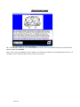
SPECIAL MODE: VOLKSWAGEN LIVE DATA
In those systems with live data available for Volkswagen, once you click on “Live data” will open the following window:
1
1. VAG Mode: is the way the original scanner from VW presents live data. You need to have the original
documentation to use this mode in 100%
2. Expert mode: is the traditional way SPCMAX shows Live Data (measuments).(For more information go to
“Connection to the vehicle-Third screen” and then “Measurement” (Live data).
17 of 34
FAULT READING- FORTH SCREEN
Figure 13 and 14 - Trouble code reading
Figure 15 - Not applicable
Figure 16 - ABS by Flow Screen
This screen changes according to the car Make and/or Injection system. The different screens are shown on figures No.
13, 14, 15 and 16.
Necessary steps to make the reading:
• Put the ignition key in “on” or start the engine, according to on-screen message.
• Communication with ECU starts when clicking on “START”. SPCMAX reads the fault memory (all RECORDED faults will
be seen on screen).
» BASIC ADJUSTMENT OR AUTOADAPTATION
The adjustment needed each time the vehicle is repaired can be made by BASIC ADJUSTMENT or AUTOADAPTATION
(qualified marks only), for erasing the autoadaptation memory.
» ACTUATORS TEST
On this screen you may also find the ACTUATORS button (qualified marks only). This test is manually made and activates
the actuators one by one to check its proper work and communication with the command unit (ECU)
» DYNAMIC TEST (KOER)
On FORD EEC IV faults screen, there is a button available to allow to perform the DYNAMIC TEST (KOER).
Engine must be on and at working temperature range.
18 of 34
» STATIC TEST (KOEO)
On FORD EEC IV faults screen, there is a button available to allow to perform the STATIC TEST (KOEO).
Engine must be off and at working temperature range.
Other makes or systems may have more functions.
» FAULT MEMORY ERASURE
Once repair is completed, the faults memorized by ECU should be erased. Click on the Clear memory button.
» BACK
Click BACK to return to the Model and System Selection screen.
» DATABASE
Option DATABASE is located on the top left side of the Trouble Code Reading screen. Click there and select Complete
Damage Car to go to DATABASE screen.
Database is located in the Clientes SPCMAX.MDB file, in "Microsoft ACCESS" format and may be edited by such program.
To make a backup just copy this file.
You may also backup the file by clicking on “Back up” in the “DATA BASE” menu bar.
NOTE: we strongly recommend to make diary back ups to avoid any lost of data.
Once you enter to the data base screen you will be placed in the customer screen (see below). In case there are
customers loaded, the system will show the first customer entered.
Screen 1.
Sector 1
Sector 2
Screen 2
19 of 34
Sector 1
Sector 2
1) Shows customer information and allows the entry of new customers.
2) Allows customer or vehicle search.
• Customers
In order to enter a new customer, click on button “Add”, as shown in screen 1, sector 1. The cursor will be placed
automatically in the “Entreprise” and the screen will be just as Screen 2. The fields marked with “*” are compulsory fields
and have to be completed in order to charge a new customter. In case one of these fields is not completed, there will be no
possibility to continue and will appear an screen message notifying to complete that missing information.
Once you finished to enter your customer information, click on “Update” to finish the process or “Cancel” to cancel the
action.
To Elimnate one customer from database, click on “Eliminate”.
Screen 3
In order to see each customer in database, press on the arrows in Sector 1(detailed on Screen 3) located left and right
from “Registration: x of y”. X = number of customer on screen. Y= total customers loaded.
Arrows located at the end of both sides, will locate the first and last customer. (from left to right) The other arrows will show
the next or the last customer shown.
•
Customer Search
To search a customer in a fast way, kindly refer to Sector 2 in Screen 1, where there are various ways to find a customer:
- Entreprise
-Customer name
-Phone
-License plate
20 of 34
There is no need to load every field of this sector. You can load either Enterprise, or Customer name, or phone or license
plate or a combination of them.
Once you enter one or more fields, click on “Search” to find the customer. Click on “Cancel” to erase any information you
entered in Sector 2.
If you made a search, the only registers showhn will be that ones according to the information you entered on the search
panel. If you want to see all the registers, click on “Cancel” in the search panel.
•
Cars
In this screen you have to enter the car of your customer. In order to enter a new car, click on “Add”, the screen will open
as Screen 2. Fields marked with “*” are compolsury fields. The first field – Brand- can be loaded as follows:
Click on the arrow as seen in Screen 3, where it will display a menu with all the brands available on SPCMAX. Once brand
is selected, click enter. Then it will go automatically below to enter the "Year”. Once you enter the “Year”, click enter and
repeat the same procedure with “Model” and “Engine”. There is a possibility that the model and the engine are not in
database. In that case, directly the model and the engine afterwards. If you selected a model from the list, that will open a
engine list from where you can pick an engine. Again, if you do not find the engine, write it directly.
Press the “ESC” key to return to the last data you loaded, to recorrect it.
After entering Brand, Year, Model and Engine, Color, License plate and VIN number are also requested (where License
plate is also compolsury as well as Brand, Year, Model and Engine.
To save the information and finishing the process, click on “Update” . To cancel the process, click on “Cancel”.
If you wish to delete a car, click on “Eliminate”.
Scren 1
Screen 2
21 of 34
Screen 3
Screen 4
In order to see the vehicles loaded for that customer, press on the arrows in Sector 1(detailed on Screen 4) located left and
right from “Registration: x of y”. X = number of customer on screen. Y= total customers loaded.
Arrows located at the end of both sides, will locate the first and last customer. (from left to right) The other arrows will show
the next or the last customer shown.
Once car is entered, you may access readings or Live data according to your needs. Next you find instructions on how to
use both “Readings” and “Live data”.
• Readings (DTC’s)
First you have to make a reading in order to have data to save. Once you have the reading, click on “Add” to add the data.
You will have to charge manually Km/miles. We recommend you charge this every time you make a reading. It also allows
to change the date and time (in case the are wrong in your computer) Finally, there is a space to write anything you like,
“Comments”. All the rest of the data are automatically charged and can not be changed.
To save the information, click on “update”, as shown in Screen 2
Screen 1
22 of 34
Screen 2
Readings can be printed or deleted. To delete a reading, clik on “Eliminate”. To select a reading, use the arrowds at the
bottom of the screen, as shown in other examples.
• Live data (measurements)
First you have to make a reading in order to have data to save. Once you have the reading, click on “Add” to add the data.
The information you will be able to change is:
- Date
- Hour
-Comments
All the other information is automatically loaded and can not be changed.
To save the information, click on “update”, as shown in Screen 2
Screen 1
23 of 34
Screen 2
Readings can be printed or deleted. To delete a reading, clik on “Eliminate”. To select a reading, use the arrowds at the
bottom of the screen, as shown in other examples.
» DATA PRINTING
To print faults click on Print option of the menu, located at the top of the Trouble Code Reading (DTC’s) or “Live Data”
screen.
You can also print the vehicle file including the faults. Click on DATABASE, then click on Complete damage card, click on
the ADD button and fill in the Vehicle and Customer data (if the record is being filled) If not, look for the file you want to
print (if the file is loaded).Click on Print button and printing will start. If you have created a new file, the information will also
be saved (including the date and time of the inspection made) in the Database, which may be seen from the first screen
24 of 34
(SPCMAX).
INCOMPATIBLE PRINTERS
Drivers for (Laser) printers HEWLETT PACKARD Models: 5 L, 6 L and C L, are NOT compatible with the SPCMAX
software.
Trouble Code Reading through OBDII Screen
Figure 18 - Fault Reading through OBDII
Figure 19 - Measurement Reading through OBDII.
On this screen, click first on any of the buttons located at the bottom of the screen. ("MEASUREMENTS", "Read DTC'
s",
"Lambda Test", "Clear", "Freeze Frames")
This way communications with the command unit are activated. Select the type of system to be verified, clicking on the
open menu located on the top right side of the screen.
Once the system is selected, data will be updated. To end click on “BACK”.
25 of 34
"Reset Service" screen
Figure 20 - Setting to zero the Service Indication
This screen will appear when you select "INSTRUMENTS" from the second screen (Model and System Selection) Select
vehicle and click on "SCANNER"
On this screen, steps to be followed to do the "Setting to zero the Service Indication" are thoroughly explained. Consists of
erasing the service requirement by the vehicle, once it has been done.
26 of 34
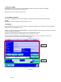
Digital Voltmeter
Description
1. Channel 1 or Channel 2 (K and L Lines): measures the input voltage
Channel 1 / Channel 2: by the entries at the front of the scanner.
K-Line / L-Line: by the scanner pins (bananas).
2. Power supply entry: measures scanner’s power supply voltage.
3. Selectable Voltmeter entries:
Oscilloscope: if “Oscilloscope” button is pressed, entries are: CH1 and CH2 at the front of the scanner
Scanner: if “Scanner” button is pressed, entries are: K and L-Lines from the scanner.
NOTE: to measure voltage in K and L-Line, a system (injection, abs, etc) must be selected before.
4. CH1 / CH2: this buttons allow to show Channel 1, Channel 2 or both together. Pressed: that channel is
shown. Not pressed: channel not shown.
5. Selection of maximum range to measure:
Voltmeter allows to adjust ranges depending on the voltage to be measured.
NOTE: This does not mean it will measure till voltage selected. It means the scale shown by
Voltmeter will be up to that voltage ( 7 V, 20 V or 200V)
WARNING: Maximum input Voltage is 200 Volt peak to peak. Higher Voltage than described will cause
irreparable damage to this equipment, which will not be covered by warranty.
6. Alternative or Direct current selection:
DC: Direct current entry selection
AC: Alternative current entry selection
7. Start / Stop:
“Start” button: click here to start measures.
27 of 34
“Stop” button: click here to stop measures.
8. Oscilloscope or Voltmeter:
“Oscilloscope”: click on “Oscilloscope” to go to Oscilloscope screen.
“Voltímetro¨: click on “Voltmeter” to go to Voltmeter screen.
WARNINGS
WARNING
THIS VOLTMETER IS ONLY FOR VOLTAGES UP TO 200 V PEAK TO PEAK
FORBIDDEN USES:
USE IN IGNITION FORBIDDEN
USE IN CRANKSHAFT WITH THE ENGINE IN HIGH RPM FORBIDDEN
PRECAUTION WITH INDUCTIVE CHARGES WHOSE PEAKS COULD BE MORE THAN 200 VOLTS
HIGHER VOLTAGE THAN DESCRIBED WILL CAUSE IRREPARABLE DAMAGE TO THIS EQUIPMENT,
WHICH WILL NOT BE COVERED BY WARRANTY
2 Channels Oscilloscope
Description
1. Oscilloscope Screen
Shows the waves graphed by Oscilloscope.
“X” shows times in ms (miliseconds), according to selected scale (For more info, go to 3. below)
“Y” shows voltage, according to selected scale. (For more info, go to 7. below)
NOTA: to chage color line, put the mouse over any line. Click on right button to change color.
2. Cero level adjustment
Select the cero level more convenient according to measure.
28 of 34
3. Time selection
By 5ms, 20ms, 50ms y 100ms buttons “time per division” is selected. (“X” axis)
4. Trigger
¨Trigger¨ means: point of signal when Oscilloscope acts.
4a. Trigger manual level adjustment: select Trigger manually with this bar.
4b. Trigger ascendant signal
4c. Trigger descendant signal
4d. Shoot indication:
Automatic: blinks when Automatic Shoot is
Manual: off indicates that is stopped or Trigger shoot levels are not reached. Blinks: when it reaches Trigger
shoot levels.
NOTE: Use of Automatic shoot is recommended.
5. Selectable Oscilloscope entries:
Oscilloscope: if “Oscilloscope” button is pressed, entries are: CH1 and CH2 at the front of the scanner
Scanner: if “Scanner” button is pressed, entries are: K and L-Lines from the scanner.
NOTE: to measure voltage in K and L-Line, a system (injection, abs, etc) must be selected before.
6. CH1 / CH2: this buttons allow to show Channel 1, Channel 2 or both together. Pressed: that channel is
shown. Not pressed: channel not shown.
7. Selection of maximum range to measure:
Oscilloscope allows to adjust ranges depending on the voltage to be measured.
NOTE: This does not mean it will measure till voltage selected. It means the scale shown by
Oscilloscope will be up to that voltage ( 7 V, 20 V or 200V)
WARNING: Maximum input Voltage is 200 Volt peak to peak. Higher Voltage than described will cause
irreparable damage to this equipment, which will not be covered by warranty.
8. Alternative or Direct current selection:
DC: Direct current entry selection
AC: Alternative current entry selection
9. Start / Stop:
“Start” button: click here to start measures.
“Stop” button: click here to stop measures.
10. Oscilloscope or Voltmeter:
“Oscilloscope”: click on “Oscilloscope” to go to Oscilloscope screen.
“Voltímetro¨: click on “Voltmeter” to go to Voltmeter screen.
WARNINGS
WARNING
THIS OSCILLOSCPE IS ONLY FOR VOLTAGES UP TO 200 V PEAK TO PEAK
FORBIDDEN USES:
USE IN IGNITION FORBIDDEN
USE IN CRANKSHAFT WITH THE ENGINE IN HIGH RPM FORBIDDEN
PRECAUTION WITH INDUCTIVE CHARGES WHOSE PEAKS COULD BE MORE THAN 200 VOLTS
HIGHER VOLTAGE THAN DESCRIBED WILL CAUSE IRREPARABLE DAMAGE TO THIS EQUIPMENT,
WHICH WILL NOT BE COVERED BY WARRANTY
29 of 34
Special Functions
Manual Adjusment VW
(added to basic adjusment)
Injection Marelli 1 AVB / 1 AVS / 1 AVP
Since V20, SPC960 offers and option to adjust manually the
Injection Marelli 1 AVB / 1 AVS / 1 AVP
In DTC'
s screen, clicking on Basic adjustment button, will open an option
which allows you to choose between Automatic and Manual. To access to Manual Adjustment,
click on "Manual".
Then it will ask to enter the "channel", where every channel adjust the following
parameters:
Channel 1
Channel 2
Channel 3
Channel 4
Channel 5
Channel 6
Channel 7
Channel 8
Channel 9
RPM
Motor Temperature
Lambda Sond Tension
Bits Map*
RPM
Inyection Time
Battery Tension
Air Temperature ºC
RPM
Engine Load %
Throtle angle < º
*****
RPM
Engine Load %
Advance Angle
*****
RPM
Contact Cicle
Contact Cicle
Bits Map*
*****
*****
*****
*****
*****
*****
*****
*****
*****
*****
*****
*****
*****
*****
*****
Channel 9, 10, 11, 12, 13, 14, 15, 16, 17, 18, 19, till 255 - Nothing.
* Bits Map is an internal ECU parameters. Its value has NO importance to repair the vehicle.
*****
Choose the channel that includs the parameters to be adjusted and click on OK
The adjusment will be made for that parameters and will finish automatically.
We recommend to read again "Live data" to verify the adjusment was right.
WARNING: BLUETOOTH CONNECTION (WIRELESS)
Bluetooth may have problems with:
•
•
•
•
•
•
Radio frecuency Interferences (TV, radio, etc.)
Other interferences (running cars, electric installation, air compressors and other common machines found
in a garage)
Retry because of data lost
For the mentioned above, it can not be guaranteed a 100% functioning for SPC MAX connected through
Bluetooth
Bluetooth indoor range depends on the mentioned interferences. It can go from 5 to 50 meters.
For all the reasons mention above, Bluetooth connection may be slower than USB connection.
NOTE: Kit Bluetooth is optional. In order to know if you scanner has Bluetooth, check if there is an antenna over
30 of 34
the word "Bluetooth"
Special warning - Bluetooth
The antenna used for this scanner must be installed to provide a separation distance of at least 20 cm
from all persons and must not be co-located or operating in conjunction with any other antenna or
transmitter.
Any changes or modifications to the equipment not expressly approved by the party responsible for
compliance will void user’s authority to operate the equipment.
ATTENTION: Password for Bluetooth connection between scanner and PC is: “1234”.
Specifications
Connection: 1 USB 2.0 connection, 1 RS232 standard connection
Wireless connection to PC: Bluetooth Class 1 (Optional)
Power Supply: 12 - 32 Volt
Maximum Oscilloscope input in CH1 and CH2: 200 Vpk/DC
Operational temperature range: 0 - 50 °C ( 32 - 122 F)
Dimensions: 170x210x35 mm
Weight: 0.75 Kgs.
No special printer needed
2 Channel Digital oscilloscope:
Channels: 2
Selectable entries: Channel 1, Channel 2 or selected pins in scanner.
Maximum input tension (RMS): 70V.
Maximum input tension peak to peak: 200V.
Selectable range - Channel 1 and 2: DC - Graphics of positive tensions.
0 to + 7 V (7V MAX).
0 to + 20 V (20V MAX).
0 to + 200 V (200V MAX).
AC - Graphics of positive and negative tensions.
- 5 V to + 5 V (8 V peak to peak MAX).
-10 V to + 10 V (20 V peak to peak MAX).
-100 V to + 100 V (200 V peak to peak MAX) .
Ranges - K and L lines: DC - Direct current.
0 to 20 V (fixed).
Basic adjustment: Manual for each entry.
Time scales: 5ms / 20ms / 50 ms / 100 ms (per division).
Trigger: Automatic or manual Channel 1 and/or Channel 2.
Trigger level: Adjustable.
Trigger signal: Ascending or descending.
Input Impedance: < 1 M
(Ohm).
Analogic/Digital converter: 10 bits resolution.
Ground: Referred to power supply ground.
Sample rate: 10 kilosamples per second (kps)
31 of 34
Specifications may change without notice.
Freeze values: allows to freeze graphics in both Channels.
In order to measure with Oscilloscope K and L-Lines, you must select a system before. If not, it will not work.
The readings will be made over the pins connected to the car diagnostic socket.
All readings referred to power supply ground.
Specifications may change without notice.
Voltmeter:
Scanner/Oscilloscope power supply measurement.
Selectable entries: Channel 1, Channel 2 or selected pins in scanner.
Scanner Power supply entry: Power supply pins or power supply jack.
Maximum input tension (RMS): 70V.
Maximum input tension peak to peak: 200V.
Selectable range - Channel 1 and 2: DC - Direct current.
0 to 7 V MAX.
0 to 20 V MAX.
0 to 200 V MAX.
AC - Alternative current.
0 to 2.5 V RMS MAX.
0 to 8 V RMS MAX.
0 to 60 V RMS MAX .
Ranges - K and L lines: DC - Direct current.
0 to 50 V .
Frozen values: All Voltmeters.
Analogic/Digital converter: 10 bits resolution.
Ground: Referred to power supply ground.
Specifications may change without notice.
Freeze values: allows to freeze values of the 3 Voltmeters.
In order to measure Voltmeter K and L-Lines, you must select a system before. If not, it will not work.
The readings will be made over the pins connected to the car diagnostic socket.
All readings referred to power supply ground.
NOTE: readings in alternative current (AC) are calcuted based on a sine formed tension and a frecuency
between de 50-60 Htz. Any other wave formed or frecuency will create change indicated values.
Scanner Power supply entry: Power supply pins or power supply jack. In case both are connecterd, the higher
reading will be showed.
Specifications may change without notice.
32 of 34
Regulatory Information
EC DECLARATION OF CONFORMITY (EUROPE)
SPC Group declares under their responsibility that products SPCMAX (in models MEC or MAX) and
SPCTRUCK vehicle diagnostic scanners – through their representant Scanner PC Tools, SL from Spain-:
The equipment listed above conform to EMC Directive 89/336/EEC and modification 92/31/CEE and Low
Voltage Directive 73/23/EEC.
FALTA RESULTADO ENSAYOS.
Internal measures applied to guarantee the conformity of the equipment:
Registry of quality protocol
Registry of component reception
Test of internal plates before assembling in cabinet
Test in electronic control units (ECU)
Test of cables with special testers
Registry of technical support
Registry of findings of nonconformities and corrective actions
Builder certified with ISO9000
Year of CE mark: 2008
Note for equipment with Bluetooth (optional): This equipment is intended to be used in all EU and other
countries. Outdoor use may be restricted to certain frequencies and/or may require a license for operation. For
more details, contact Linksys Corporate Compliance.
Note: Combinations of power levels and antennas resulting in a radiated power level of above 100 mW are
considered as not compliant with the above mentioned directive and are not allowed for use within the
European
community and countries that have adopted the European R&TTE directive 1999/5/EC and/or the CEPT
recommendation Rec 70.03. For more details on legal combinations of power levels and antennas, contact
Linksys Corporate Compliance.
33 of 34
• "The brands mentioned on the SPCMAX listing are registered in several countries, incluiding this one. And they are
property of the automotive industries to which each of them belong."
• "Las marcas mencionadas en el listado del SPCMAX, se encuentran patentadas en nuestro y otros países. Y son
propiedad de las empresas automotrices a la que corresponde cada una de ellas."
• As marcas mencionadas na lista do SPCMAX se encontram patentadas em nosso país e em outros. Sào propriedade
das empresas automotoras à qual corresponde cada uma delas.
• Die im SPCMAX genannten Marken sind in unserem und andere Ländern registriert worden und sind Eigentum der
zugehörigen Fahrzeughersteller.
• Les marques mentionnés dans la liste du SPCMAX se trouvent déposées en Argentine et dáutres pays. Elles sont
propriété des entreprises automobiles correspondantes.
34 of 34