1
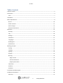
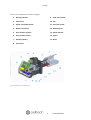
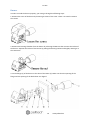
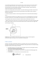
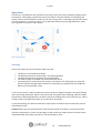
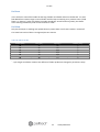
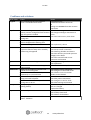
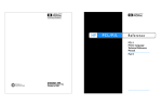
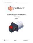
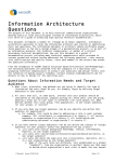
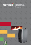
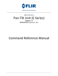
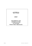
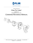
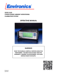
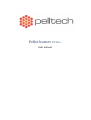
Pellet burner PV 20a User manual PV 20a Table of content Table of content.....................................................................................................................................2 Description.............................................................................................................................................4 Fuel.....................................................................................................................................................7 Installation..............................................................................................................................................7 Boiler requirements................................................................................................................................8 Burner...............................................................................................................................................10 Pellet container................................................................................................................................11 External auger..................................................................................................................................12 Electrical connections.......................................................................................................................12 Operation.............................................................................................................................................15 Starting.............................................................................................................................................15 Log....................................................................................................................................................16 Settings.............................................................................................................................................16 Info Menu.........................................................................................................................................17 Languages.........................................................................................................................................17 Refilling fuel......................................................................................................................................19 Maintenance....................................................................................................................................19 Working principle.................................................................................................................................21 Testing..............................................................................................................................................21 Loading.............................................................................................................................................21 Igniting..............................................................................................................................................21 Preburn.............................................................................................................................................21 Burning.............................................................................................................................................22 Auger control................................................................................................................................22 Fuel level detection......................................................................................................................22 Output power levels ....................................................................................................................22 Hold flame........................................................................................................................................22 End burn...........................................................................................................................................23 End blow...........................................................................................................................................23 Controller board description................................................................................................................24 Problems and solutions........................................................................................................................26 Warranty..........................................................................................................................................27 2 www.pelltech.eu PV 20a Safety precautions Do not start the burner before it is connected to the boiler and the boiler is connected to the chimney. It is recommended to wear a respirator while handling pellets. The boiler room where the burner is installed must fulfill all rules and recommendations given by authorities. All electrical connections must be done by trained professionals. No flammable materials must be stored near the burner. Warnings Changing the construction of the burner without written permission from the manufacturer is forbidden. Use only spare parts provided or approved by the manufacturer in order to avoid any damage to the burner and dangers resulting from it Welding is allowed only after disconnecting the burner from electric supply. The circuit board must be removed from the burner. Do not open any boiler door while the burner is in operation. The burner complies with following directives and standards Directive 2004/108/EC Directive 2006/95/EC Directive 2001/95/EC Directive 2006/42/EC EN 15270 2008 EN 230 2005 EN 60370-2-5 2002 3 www.pelltech.eu PV 20a Package content The burner is shipped with following components included: 1. Grate 2. Burner 3. Brackets for hose (2x) 4. Flange 5. Ceramic seal 6. 7-pole boiler connector 7. Hose 8. User manual Description PV 20a is a pellet burner that is intended to be used with 6 or 8mm wooden pellets. You cannot use any other fuel to run this burner. The unique construction of PV 20a allows it to be used with different boilers: liquid fuel, solid fuel and universal boilers. The PV 20a burner is connected to the boiler with a 90 mm flange (similar to oil burners). The burner is equipped with a safety thermostat, a melting chute, temperature sensor and auxiliary battery for protection against back-burning. 4 www.pelltech.eu PV 20a Burner main components are shown on Figure 1 1. Burning chamber 9. Feed screw motor 2. Feed screw 10. Fan 3. Safety cut off thermostat 11. Fuel level sensor 4. Mains transformer 12. Mounting nut 5. User interface joystick 13. Flame detector 6. User interface screen 14. Igniter 7. Auxiliary battery 15. Grate 8. Connectors Figure 1 Burner main components 5 www.pelltech.eu PV 20a Figure 2 Dimensions Table 1 Specification L total length L1 burner body length L2 burning chamber length ⌀D burning chamber diameter ⌀D1 burning chamber neck diameter ⌀D2 internal feeder inlet diameter H total height H1 burner housing height W total width W1 burner housing width Mass Supply voltage Power max Power average Power at standby Noise Emission class1 Operating temperature Nominal heat input Min heat input Unit mm mm mm mm mm mm mm mm mm mm kg VAC W W W dB Co kW kW PV 20a 530 230 170 146 88.9 60 250 200 220 204 11.2 220-240 570 25 - 40 7 52 5 0-60 20 10 1. According to EN 15270 6 www.pelltech.eu PV 20a Fuel PV 20a uses premium wooden pellets as fuel. Wood pellets are concentrated and homogenized fuel made from sawdust and cutter shavings. Pellets are pressed with high temperature. No extra materials are added, pellets are held together by a natural ingredient found in wood – lignin. Pellets are CO2-neutral, renewable fuel. Pellets must be stored in a dry and ventilated room. It is recommended to wear a respirator when handling pellets. Only premium class pellets can be used with PV 20a. Refilling must be carried out before the storage runs empty. In case it happened, burner has to be restarted and the loading time can be up to 20 minutes that external auger has enough time to refill itself. Table 2 Pellet properties Raw material sawdust and cutter shavings Calorific value 4700-5100 kWh/ton Volume weight ca 650-670 kg/m3 Volume of 1 ton 1.5-1.6 m3 Diameter 6-10 mm Length 3-5 x diameter Water content 8-10 % Ash content Ca 0.5% To replace 1000 l light oil ca 2 tons or 3 m3 Installation You will need the following tools in order to install the burner: • • • • Spanner no. 13 for fixing the flange of the burner to the boiler Spanner no. 10 for connecting the body of the burner with the burning camber Cross-head screwdriver for fixing the cover of the burner 4 mm hex wrench for fixating the boiler to the flange In order to install the burner, the boiler must correspond to the following requirements: • • • • • The door of the boiler must have a 90 mm opening (placement opening for the oil burner). The thickness of the boiler door must be less than 100mm The construction of the boiler must make it possible to open the door of the boiler with the burner connected and removing ash from the furnace. If the door of the boiler is too narrow for opening it with the burner, then extra hinges must be installed. If there is not sufficient (less than 5Pa) negative pressure in the furnace, a draught fan should be installed for the exhaust gases. The boiler room where the burner is installed must fulfill all rules and recommendations given by authorities. 7 www.pelltech.eu PV 20a • The boiler must be positioned in a way that there is enough space for cleaning the burner, the boiler and the smoke pipe and removing the ash. If flue gas temperature at the top of the chimney is less than 80C o, there is a risk of condensation. In this case a pipe should be installed throughout the length of the chimney. Note: It is recommended to use a flue gas analyzer for adjusting the burner. The burner must be adjusted using the flue gas analyzer also when you change the size or the quality of the pellets. Boiler requirements Pellet burners need regular cleaning and therefore boiler construction must allow the door to be opened without removing the burner. The minimum size of opening in boiler depends on the position of door hinges and vice versa. Figure 3 below illustrates the situation. Point C is critical. In order to keep door width minimum and boiler opening small, a double hinge solution can be used. As double hinges add another degree of freedom, door must be fastened on both sides. Slide-out doors with guide rails is also an option. Figure 3 Hinge position and boiler opening size considerations Figure 4 Double hinges 8 www.pelltech.eu PV 20a Boiler firebox length L (Figure 5) should be at least 2,5 x the length of the burning chamber. For PV 20a, minimum of 420mm is acceptable (leaving L1 approx. 250mm). The height should be enough to leave H1 below the burner about 100mm for ash. Minimum dimensions L and H for PV 20a: L≥420mm; H≥350mm. Figure 5 Boiler firebox requirements Burners are mounted to door using supplied oil burner flange. Bolt hole circle diameter and bolt sizes can be customized by using custom flanges. D1 and D2 given in Table 3 are only valid with supplied flanges. Table 3 Mounting holes for boiler door ⌀D hole for burning chamber neck ⌀D1 flange bolt ring diameter ⌀D2bolt holes Unit mm mm mm 90 130..150 8..9 Figure 6 Mounting holes with supplied flanges for boiler door 9 www.pelltech.eu PV 20a Burner In order to install the burner properly, you must go through the following steps: 1. Remove the cover of the burner by loosening 4 screws of the cover. There is no need to remove the screws. 2. Remove the burning chamber from the burner by releasing the M6 nut that connects the halves of the burner. Separate the halves of the burner by pulling the burning camber and slightly rotating it at the same time. 3. Fix the flange (2) of the burner to the door of the boiler (1). Make sure that the opening of the flange and the opening of the boiler door are aligned. 10 www.pelltech.eu PV 20a 4. Fix the burning chamber (8). For that you need to put a ceramic seal (4) on the narrower side of the burning chamber and then put the camber through the door of the boiler in a way that the rearward wall of the burning chamber would lean on the door of the boiler. Fixate the burning chamber with two grub screws (10) to the flange. Caution! The burning camber must be placed in a way that the burning grate will be as horizontal as possible. The connection between the burner and the boiler must be tight in order to avoid any leakage of smoke gases. 5. Connect the body of the burner to the burning chamber like it was done before disassembling in step 2. 6. Fixate the halves of the burner with a M6 nut (9). The nut has to be rolled tight but not too hard. The halves of the burner are connected correctly when there is no space between the mark on the connecting tube (a line drawn on the tube with a dark marker) and the body of the burner. 7. Make sure the halves of the burner are connected correctly. Make sure that when looking through the fire tube the igniter end tip is at the same level with the wall. The tube of the inner auger must reach through its opening. Caution! After the installation of the burner always make sure that the end of the igniter is positioned through its opening and not stuck behind the dividing wall. Pellet container The burner, the auger and the pellet container are a common system. The size and the location of the pellet container depend on the needs and possibilities of the specific boiler room. While choosing the pellet container you must keep in mind that: • • • • If the pellet container is in the same room as the boiler, then the size of the pellet container must not exceed 500 liters (approx. 350kg). The container must be made of fireproof materials. The container must be positioned in a way that the raising angle of the feeding auger does not exceed 45°. It is advisable to use a container that can be closed with a cover. 11 www.pelltech.eu PV 20a External auger A feeding auger transports pellets from the pellet container to the burner. The burner controls the work of the auger. The auger is connected to the burner with a special hose. The hose is made of melting material that acts as a safety measure against back-burning. The uppon side of auger (with motor) must be fixed to a storage or to some other object nearby (with delivered chain) . Figure 7 shows correct position for external auger. As the hose is a safety device, it must be placed strictly as described below. The vertical distance between auger outlet and burner inlet must be in range of 40..70cm and horizontal displacement 10..20cm (typical auger angle 30 o..45o). External auger cannot be installed in position with angle greater than 45 o. The hose must be in angle of 50o or more to ensure free falling of the fuel. Figure 7 External auger installation (units in mm) Electrical connections The burner is equipped with a standard oil burner plug that has 7 contacts. There will be different connection schemes used for different boilers. Usually the burner is connected to the boiler with a 5wire cable. It is also possible to connect with a 4-wire cable. Caution! All electrical connections of the burner must be made by a qualified professional. 12 www.pelltech.eu PV 20a Figure 8 Burner 5-wire connection Chs – Chassis grounder M1 – Fan M2 – Flue gas fan* M3 – External auger M4 – Internal feeder Ot – Safety thermostat Figure 9 Burner 4-wire connection R1 – Flame sensor SBB – Controller board Se – Igniter TR – Transformer Tt – Boiler thermostat *Flue gas fan M2 is installed only if there is not enough draught. The flue gas fan is not included with burner. 13 www.pelltech.eu PV 20a Operation The burner is controlled via user interface on the front panel. LCD screen (1) displays settings menu, event log etc. Yellow light (2) shows the presence of flame in burning chamber. Or if blinking, the burner is out of normal operation. Status can be seen on log screen. Green light (3) indicates if there is fuel in the burner. To move in menus, use up and down buttons (4), to change parameter, press OK, to go back to LOG press “ESC” button. Figure 10 Front panel Starting Prior to the initial start-up of the burner make sure that: • • • • • The burner is connected to the boiler The boiler thermostat is installed and is functioning properly The boiler thermostat is turned to lowest temperature The external auger is installed and connected to the burner The smoke duct is connected to the chimney, the dampers for smoke gases are open and there is sufficient draught. When the burner is operating, the negative pressure inside the boiler must stay between 4-6 Pa To turn on the burner, switch on boiler main switch. If burner displays ’Stopped’, then go to settings menu and change parameter ’Burner’ from OFF to ON. The display shows ’Waiting’. Now turn boiler thermostat to desired temperature. The burner will go to Loading-state. If this is the first run, external auger needs to be filled with pellets. It can take up to 20 minutes. To stop the burning, turn boiler thermostat to lowest point. The burner will now finish the process after all fuel is burnt. Caution! Never turn off a working burner from the main switch of the boiler. Use the thermostat switch for that purpose. In order to stop safely, let the burner burn empty. Do not leave the burner unattended when it has been necessary to use the emergency stop. 14 www.pelltech.eu PV 20a Log Log screen displays last events (burner states) and their duration. All states are described in Table 4. The duration is in form mm:ss (’m’ in the middle) or hh:mm (’h’ in the middle). For example ’Igniting 01m25 means the burner ignition state lasted 1minute and 25 seconds. Last row of the log shows current state. To reach the last row, press the “down” button, until you reach the current state. The duration of current state updates every second or minute. Table 4 Burner states NO PELLETS Description The burner is not switched on. The burner is switched on and waiting for command from the thermostat of the boiler. Testing the fan, battery, feeder. Loading pellets into burner for ignition after the command from boiler thermostat. Second try if the first ignition was not successful. Loaded amount of pellets are in the burning chamber, igniter and fan are working till photocell recognizes flame. Only the fan is working, the igniter is off. Pellets start burning properly. Status of normal working: External auger works by level sensor, internal auger and fan are working by. Photocell must see the flame. Boiler has reached an estimated temperature and boiler thermostat switched off, pilot flame is held in the burning chamber. Boiler has reached an estimated temperature and boiler thermostat switched off the burner. The external auger has stopped, the internal feeder and fan are still working until all fuel is burned. When photocell doesn`t see any flame only the fan keeps on working with minimum speed in order to make sure there is no fuel in burner. Level sensor does not detect pellets NO FLAME There is no flame in the burner more than 120 seconds during burning. OVERHEAT Temperature in the burner has reached preset temperature and burner turned off. IGN.ERROR Flame is not recognized after ignition LEVEL ERR Level dose not reached or level dose not disappear at burning time FEEDER ERR Jam in feeder or feeder rotation is not detected FAN ERROR Fan rotation problem BATTERY LOW Battery is not connected or empty NO POWER Supply power is not detected – burner works on battery Status STOPPED WAITING TESTING LOADING LOADING2 IGNITION PREBURN BURNING HOLD FLAME BURN END END BLOW Settings To enter settings menu, press OK. To go back to log screen, press ESC. 15 www.pelltech.eu PV 20a Table 5 Main menu Men u nr 1 2 Menu parameter ENG STATUS-> INFO-> 3 4 5 6 7 BURNER HOLD FLAME PELLETS POWER BASE AIR 8 9 LANGUAGE PARAMETERS -> Description Default value Selection list Submenu for status information *1 Information from burner devices * 2 Turn burner ON/OFF Flame holding allowed *3 Select fuel quality Actual power level Fan speed correction for all fan speeds Language selection *4 Parameter setup menu OFF ON/OFF OFF ON/OFF/AUTO NORMAL NORMAL/LIGHT/HEAVY AUTO AUTO/10/12/14/16/18/20 0 -2/-1/0/+1/+2/+3/+4/+5 ENG See language list *1 – see “Status menu description” *2 – see “Info menu description” *3 – see “HOLD FLAME” status description *4 – see “Languages” chapter Info Menu To enter info menu, move in the main menu until the row INFO and press OK. Content of info menu is following: TOTAL = total amount of pellets burned with this burner. Amount is updated after every 10 kg. COUNT = amount of pellets burned since last zero. Amount is updated after every 0,1 kg. To zero the amount, be sure you are in this menu and hold down OK for 5 sec. FAN = fan rotation speed as it is / fan rotation speed as it should be ± base air (selected base air in the main menu) P = currently working power/ power as it should be T = burner internal temperature U = Battery voltage level I = Feeder current DRAUGHT = when underpressure sensor is connected, draught is shown. Languages To change the burner language, move in the main menu until the row LANGUAGES and press OK. Choose the requested language and press OK. Burner has following languages: english (ENG), estonian (EST), finnish (FIN), french (FRA), german (GER), greek (GRE), latvian (LAT), lithuanian (LIT), dutsch (NED), portuguese (POR), russian (RUS), serbian (SRB), spanish (SPA), slovakian (SLV), swedish (SWE). 16 www.pelltech.eu PV 20a Table 6 Parameters menu Parameter Nr Name Description Unit Default Value Min. Max. 1 BURN AIR @10kW Fan speed at power level 1 rps 22 20 24 2 3 4 5 6 7 8 9 10 11 BURN AIR @12kW BURN AIR @14kW BURN AIR @16kW BURN AIR @18kW BURN AIR @20kW TESTING AIR IGNITION AIR BURN END AIR HOLD FLAME AIR HOLD FLAME ON rps rps rps rps rps rps rps rps rps min 25 27 30 34 38 42 25 20 10 15 23 25 28 32 36 38 20 10 7 5 27 29 32 36 40 50 35 30 14 30 12 HOLD FLAME OFF min 60 30 90 13 14 15 16 kW kW min min 12 18 60 30 10 10 30 15 20 20 120 45 21 22 23 24 25 MIN POWER MAX POWER AUTO POWER UP AUTO POWER DOWN PELLET NORMAL PELLET LIGHT PELLET HEAVY LOADING FEED LOADING 2 FEED Fan speed at power level 2 Fan speed at power level 3 Fan speed at power level 4 Fan speed at power level 5 Fan speed at power level 6 Fan speed for testing Fan speed during ignition cycle Fan speed durinf end blow cycle Fan speed during hold flame cycle In case of Hold flame is set on AUTO, flame holding activated after 2 waiting session, both less then 15 min. In case of Hold flame is set on AUTO, there is maximum time for flame holding cycle. Minimum power level Maximum power level Internal feeder production Internal feeder production Internal feeder production Feeder turns during loading cycle Feeder turns during second loading cycle g/rot g/rot g/rot rot rot 33 31 35 21 3 28 28 28 20 1 38 38 38 24 8 26 30 31 BURN END FEED SMOKEFAN ON SMOKEFAN 1 rot 0/1 % 15 0 40 10 0 0 20 1 100 32 SMOKEFAN 2 % 60 0 100 33 SMOKEFAN 3 % 80 0 100 40 41 42 43 PHOTOCELL PREBURN TIME PREBURN CYCLES OVERHEAT TEMP % s n °C 84 50 2 50 50 30 1 20 100 100 4 70 50 ON ERROR RELAY 99 MODEL VERSION 0- OFF, 1 - ON Smokegas fan speed for ignition, end blow, burn at power level 1 and 2 Smokegas fan speed for burn at power level 3 and 4 Smokegas fan speed for burn at power level 5 and 6 Photocell sensitivity Preburn cycle lenght Maximum allowed burner temperature Error output relay contacts (ON - NO or OFF -NC) Load default settings for chosen burner model or change model type 17 ON 0 ON/OFF 20a www.pelltech.eu 20a/30a/50a/ 100a PV 20a Refilling fuel The fuel storage must be refilled before it runs empty. Fuel can be added at any time during the operation. To add fuel, simply pour a new bag of pellets into your fuel storage. If the storage runs empty before new fuel is added, the external auger must be loaded again as described in chapter Starting. Failing to do so will result ‘No Pellets’ due to fuel loading timeout. Maintenance Pellet burner PV 20a requires systematic maintenance. The maintenance period depends on the quality of the pellets and heating intensity. The average maintenance period is 1 week. The burner needs cleaning when the ash layer on the grate is thicker than 1.5-2 cm. As even high quality pellets contain 0.3-0.5% ash, then the burning grate must be cleaned at least once a week. Depending on the quality of the pellets, it might be necessary to clean the burner more frequently. To clean the burner: 1. 2. 3. 4. 5. 6. Turn off the burner by turning the thermostat to 0. Let the burner cool down for at least 1 hour. Open the boiler's door to gain access to burning chamber Remove the grate and clean it from any residue. Make sure all holes on the plate are clean. Remove ash from burning chamber. Clean the boiler. The frequency of cleaning the boiler depends on the type of the boiler and heating intensity. For more information about cleaning the boiler, please see boiler's user manual. 7. Put back the grate. Make sure the stopper of grate is touching the burning camber from inside. Misaligned base plate will change the air flow and reduce burning efficiency. 8. Close the boiler's door to finish the maintenance and turn the thermostat to desired temperature. NB! The burner grate must be checked and cleaned once a week. This assures trouble-free and effective operation of the burner. The connection between the boiler and chimney must be completely tight. All cleaning and maintenance openings must be closed with covers. Feed screw motor The condition of the feeding screw motor is crucial for safety. Therefore the motor must be replaced after every 2000 working hours or after 40-50 tons of pellets are burned or when the burner gives warning. Burnered pellets amount (in kg) is accessible from info-menu. Battery Battery must be replaced when the burner gives warning message or after 5 years. As the battery is also safety device, burner monitors the state of battery and blocks next work cycle if battery voltage is not within limits. 18 www.pelltech.eu PV 20a Fan The air in boiler room contains dust that can deposit on fan bearings. The best cure is to keep boiler room as clean as possible. Otherwise the fan bearings can get stuck after several years of working and must be replaced. Resetting safety thermostat In case of overheating the burner flashes yellow indicator and displays message OVERHEAT. The safety thermostat must be reset manually. Thermostat is located on the horizontal tube of inner auger. 1. 2. 3. 4. 5. 6. Make sure the burner has cooled down and disconnected from power supply. Remove the cover by loosening 4 screws (2 on both sides) Press small button on thermostat. Connect power supply Press OK for 5s If indicator keeps flashing, you need to replace the thermostat. Figure 11: Resetting the safety thermostat 19 www.pelltech.eu PV 20a Working principle Testing Before every startup the burner tests itself. At testing time fan is turned on at maximum power. If its speed doesn´t reach 30 rps, “fan error”will occure on display. Battery loading is turned off and feeder is turned on. If battery voltage is lower then 12V, “Battery low” error will occure. By testing the feeder has to make 1 full turn in 8 seconds, if it fails to do it, “feeder error” will occure. Loading In the loading cycle, internal feeder loads correct amount of fuel into burning chamber needed for ignition. Loaded fuel amount is measured by counting internal feeder rotations. Loading is correctly ended when feeder has made 22 rotations. Internal feeder working depends on fuel level sensor: • • If level sensor recognizes fuel in burner for more than 1s, the feeder is started If feeder makes 1.5 rotations without fuel in burner then the feeder stops External auger is holding permanent fuel level in the feeder tube all loading time depending on level sensor: • • If level sensor does not recognize fuel in burner more than 1s, the auger is started. If level sensor recognizes fuel in burner more than 5s, the auger is stopped. Maximum loading time is limited with 5 minutes in normal working conditions and 20 minutes after manual start. Igniter is preheated in the end of loading cycle. When internal auger has made 10 rotations (full load rotations* - 12) the igniter is turned on for preheating. If the igniter is turned on more than 1 minute at loading time, the igniter will be turned off. • • If level sensor recognizes fuel in burner for more than 1s, the feeder is started If feeder makes 1.5 rotations without fuel in burner then the feeder stops Igniting In ignition state the igniter is heated up and fan blows hot air through loaded pellets and ignites them. Igniter is turned off after every 50 seconds to avoid overheating it, and turned on again after 20s . Preburn The purpose of preburn state is to fully ignite the pellets. No fuel is added at preburn. Fan works at the same speed as in ignition. 20 www.pelltech.eu PV 20a Burning The running position of the burner. Fuel is periodically added and fan is keeping speed according to air table. Burning state lasts until boiler thermostat is switched off. Auger control External auger is holding permanent fuel level in the feeder tube during Burning state. The auger is controlled by fuel level sensor in following manner: • • Auger is started after level sensor does not recognize fuel in burner and internal feeder has done 2 half- rotations. Auger is stopped when level sensor recognize fuel in burner for more than 1s. Fuel level detection Pellet level in vertical feeder tube is detected by fuel level sensor (optical). Fuel is detected when pellets interrupt optical link between sensor pair. Burner will enter level detection fault condition in following cases: 1. Fuel loading timeout (no signal for specified period of time) 2. Fuel unloading timeout (signal lasts longer than specified period of time) Output power levels Burner has 6 preset output power levels. For every level, program calculates correct fuel amount depending of fuel calorific value and burner internal feeder productivity. The feeder productivity for normal, light and heavy pellets can be changed from setup menu (par21, par22, par23). For most pellets it is 78g per rotation. Calculated amount of fuel is divided into periodic feeding cycles. In every cycle internal feeder makes half rotation. If the calculated cycle comes to short (less than 11s) then the cycle length is doubled and fuel is fed with by full rotation of feeder. For every power level there is different preset fan rotation speed (air table). Burner chooses the output level between preset min and max powers. When burning time has been more then 30 min, next time burner takes one level up, when burning time has been less then 15 min, next time burner takes one level down. Hold flame The main idea of this state is to reduce the number of igniting cycles. This state can be turned on automatically or manually in “hold flame” menu (ON/OFF/AUTO). If set to AUTO, burner goes to “hold flame” when the time between two startups is less then 10 minutes for 2 times. When “hold flame” lasts more then one hour, automatic mode is turned off and burner goes to “burn end” state. In “hold flame” state new fuel is fed after every 127s and fan is working by speed given by par10. 21 www.pelltech.eu PV 20a End burn In the end burn state all fuel inside the burning chamber and feeder tube must be burned - no more fuel added from external auger. Internal feeder and fan keep on working as in previous states (“hold flame” or “burning”). After the feeder has made periodically 15 half-rotations (par26), the feeder starts working continiously until 32 half-rotations is made. End blow Only the fan keeps on working with speed shown in par9 to burn out all coals. Feeder is turned off. This state lasts until no flame is recognized plus one minute. Table 7 Air table for PV 20a Power [kW] 10 12 14 16 18 20 * Fan [rps] 22 25 27 30 34 38 Cycle [s]* 26 22 18,5 16,5 14,5 13 Feeder [rot]* ½ ½ ½ ½ ½ ½ - cycle length and feeder rotations are different if feeder production changed in parameters setup 22 www.pelltech.eu PV 20a Controller board description Figure 11 Controller board 23 www.pelltech.eu PV 20a Table 8 X1 and X2 connectors X1 1 2 3 4 5 6 7 8 9 10 Description Igniter Igniter N Flue gas fan Mains transformer Mains transformer Fan L Thermostat External auger X2 1 2 3 4 5 6 7 8 9 10 Description Ash removal + Ash removal Ash removal + Battery positive terminal Battery negative terminal Flame sensor Flame sensor Feed screw - (black) Feed screw + (red) Mains transformer Mains transformer BUT – User interface buttons CONTR – LCD contrast and viewing angle adjustment FAN – Internal air fan speed feedback sensor FDR – Feed screw motor speed feedback sensor TRS – Fuel level sensor transmitter (black marking) RSV – Fuel level sensor receiver (white marking) TEMP1 – Feed screw tube temperature sensor TEMP2 – Ambient temperature sensor TEMP3 UART – RS232 interface for external modem (5V TTL). Fuses: Fuse F1 F2 F3 F4 F5 Rating 0.5A quick 1A quick 0.5A quick 3A quick 2A quick Function External auger Fan Flue gas fan Igniter Controller and feeder motor 24 www.pelltech.eu PV 20a Problems and solutions Error states Stopped No pellets No flame Cause This is actually not an error condition. Burner is turned OFF from menu. Action To turn burner on: - hold down OK button at least 3s OR - change row BURNER from OFF to ON in setup menu Maximum loading time is reached (5 or 20 - check fuel in storage minutes) and not enough fuel from external - check auger and auger connection to auger for ignition is loaded burner - check the level sensors, clean them Fuel level is not detected in 4 minutes at burning time Flame is disappeared at preburning time - check the level sensors, clean them Flame is disappeared at burning time Flame is not disappeared in end blow state - check photocell, clean it Overheat Burner internal temperature is reached over - check burner temp. from INFO menu set-point as fixed in setup menu. Possibly - check temp sensor connection back-burning is happened - check burning chamber and clean it - check the chimney and under pressure (draught) in the boiler - check the internal feeder screw connection and rotation Ignition error Flame is not detected at ignition time - check igniter and igniter fuse - check photocell Level error Fuel level in the burner has not disappeared - Check the level sensors, clean them at burning time Feeder error Feeder has not made any rotations in 8 - check feeder sensor connection seconds at its running time - check magnet on the feeder shaft - check feeder screw connection Feeder motor current is reached 0,75A - feeder can be blocked permanently in 0,2 second time Fan error Fan has not reached 40 rps in 7 seconds at - check fan sensor connection testing time with full power - check fan power connections - check magnet on the fan shaft Fan has not reached needed speed at - check fan bearings and rotation burning time in 20 sec. Battery low Battery voltage is less than 12V with load - If there was a power failure then just wait (working feeder) when it is charged - replace the battery No power No network power - check power connector, cables - check safety thermostat - check burner for backburn Safety thermostat has turned off the power - backburn 25 www.pelltech.eu PV 20a Warranty Warranty object is pellet burner PV 20a and auger PA1500 or PA 2000. Producer gives 2 years warranty from the date of sale for the burner and auger. Exeption is ignition element, for this item warranty is 1 year. Warranty does not cover defects caused by an accident, misuse, abuse, improper installation or operation, lack of reasonable care, unauthorized medication, loss of parts, tampering, attempted repair by a not authorized person, power supply errors or using poor quality fuel. 26 www.pelltech.eu PV 20a WARRANTY SHEET Burner type PV 20a Serial number ............................ Date of sale .... / ......... / ....... Customers contact details .......................................... .......................................... .......................................... Installators name and signature ........................................... ----------------------------------------------------------------------------- WARRANTY SHEET Burner type PV 20a Serial number ........................ Date of sale ..../ ........./ ....... Customers contact details .......................................... .......................................... .......................................... Installators name and signature ........................................... 27 www.pelltech.eu