1
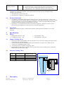
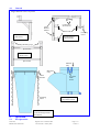
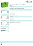
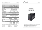
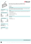
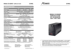
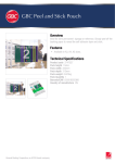
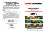
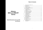
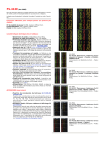
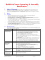
Rubbish Chutes Operating & Assembly
Instructions
1.
Purpose of Equipment
Rubbish Chute systems are intended for the guidance of falling material within the specifications of the
equipment as described below. Rubbish Chute systems are not intended for the guidance of humans or
animals, or the movement of hazardous or toxic materials. Rubbish Chutes are intended for vertical use.
2.
2.1
Safety
Warnings
•
•
•
•
•
•
•
•
•
2.2
Read and understand these instructions first before setting up or operating this equipment
Keep these instructions accessible near the Rubbish Chutes.
Before beginning work, one should become familiar with the working environment.
No changes, additions or modifications may be made to the Rubbish Chutes or associated equipment.
Do not modify, remove, bypass or override the safety devices.
Do not use this Rubbish Chute system if there is any damage or unusual performance. Isolate the Rubbish
Chute system as described in Chapter 7.1 Emergency Shutdown.
Rubbish Chutes must be secured to a structure capable of withstanding the forces described in Chapter 3
Do not operate the Rubbish Chute system if there is a risk of people being endangered by the load or the
effects of using the Rubbish Chute system. Have the area around the bottom of the Rubbish Chute system
barricaded off and post warning notices.
Observe National Plant Regulations and Occupational Health and Safety Regulations.
Hazard Assessment
Please note that this checklist is indicative only. Users must perform their own Risk Assessment subject to the
intended siting and use of the equipment.
Hazard
Risk
Control
Crushing or striking by
the Rubbish Chutes
collapsing during USE
Moderate
•
•
•
•
•
•
•
Crushing by the
Rubbish Chutes
collapsing during
ASSEMBLY
Striking or crushing by
materials falling from
the Rubbish Chute
system.
Falling from height
when erecting or using
the Rubbish Chutes
Poisoning, asbestosis,
Form 4100
Rubbish Chute Instructions
Moderate
•
•
•
Have the area around the bottom of the Rubbish Chute system barricaded
to prevent personnel from standing near the Rubbish Chute system.
Do not place articles larger than the internal diameter of the Rubbish
Chutes, or blockage and overloading may occur.
Do not use the Rubbish Chute system if blocked.
Do not use the Rubbish Chute system if overloading has occurred.
Do not allow the Rubbish Chute system to be used when maintaining the
system or changing waste bins.
Ensure Rubbish Chutes are not attached to the waste bin when the bin is
being moved.
Exercise care if the Rubbish Chutes are pulled out more than 2.4m from
the vertical axis or the top Chute may be dislodged from its mounts.
Do not remove any weights from a counterweighted frame assembly.
Low
•
•
•
Barricade off a workspace during assembly and ensure the Rubbish Chute
system is raised using safe work practices.
Ensure attachment/securing structure is of adequate strength
For counterweighted frames, do not attach Rubbish Chutes until all
counterweights are installed.
Ensure that the Rubbish Chutes are correctly attached.
Assemble as per instructions and good rigging practices.
Load material at the designated loading points only
Place barricading around the designated loading points to prevent
spillage.
Do not use a damaged Rubbish Chute system.
Barricade area at height to prevent falls.
Use height safety equipment.
Low
•
Do not install or remove a Rubbish Chute system if there is a risk that it
•
•
Low
•
•
•
•
Original issue 31st October 2000
Last reviewed 11 January 2006
Page 1 of 7
Version 5
exposure to toxic /
hazardous chemicals
2.3
•
•
will be used or has been used to move hazardous or toxic materials;
Decontamination by an approved person must be made before removal;
Inform your supervisor if adjoining structures or work areas are
contaminated by toxic or hazardous materials before starting work.
Certification
Certification to operate this equipment is not required. The person with control or management of the
workplace must ensure that:
• The Operator is at least 18 years old.
• The Operator is competent to operate the equipment.
2.4
Incident Notification
•
•
2.5
The employer, as defined by the Regulations referred to below, who has management or control of the
workplace must be aware that they may have an obligation to notify WorkCover of any incidents involving
this equipment. Refer to the Occupational Health and Safety Act and the Occupational Health & Safety
(Incident Notification) Regulation(s) applicable to your State;
If hazardous or toxic materials have been moved with this equipment, the Hirer has a duty of care to
inform Australian Scaffolds prior to the removal or return of the equipment.
Inspections
Inspections as detailed in Chapter 6: Maintenance should be performed before Installation or Use of this
equipment.
3.
Specifications
3.1
Masses
3.2
•
•
*
*
Centre Bracket : 14kg
Parapet Brackets: 12kg each
Support Loading Forces
•
•
•
•
3.3
Rubbish Chute sections: 13kg
Load Hooper sections: 9kg
Diverting the bottom of the Rubbish Chute system leads to an increase in the loading on the supports and
increases the risk of system blockage.
The maximum diversion of the Rubbish Chute system should never exceed 2.4m in radius from the
vertical axis of the Rubbish Chute system.
All anchorages must be capable of supporting 2.5kN
Rubbish Chute systems must be supported at the top and at intervals not exceeding 20m to a maximum
Rubbish Chute system length of 40m.
Structure Loading Chart
System
length
10m
20m
30m
40m
Force “F” with
vertical system
144kg
288kg
432kg
576kg
Force “F” with system
deflected to 2.4m
512kg
623kg
734kg
845kg
Fig. 1: Attachment loading forces
C
O
N
V
E
Y
O
R
&
H
O
I
S
T
F
4.
Description
Form 4100
Rubbish Chute Instructions
Original issue 31st October 2000
Last reviewed 11 January 2006
Page 2 of 7
Version 5
4.1
General
Fig. 2: Rubbish Chute Components
Centre
Bracket
Mounts
Centre Bracket
(Side View)
Locking Pin
& Clevis Pin
Rubber Pads
Clamping
Screw
Parapet Bracket
(left-hand side)
Mounting Lugs
Spacer Rail
Centre Bracket
(Front View)
Spacer Rail
Material
entry
Material
entry
Chain
Bracket
Attaching
Chain
In-system
Chain
mount
Load Hopper
(top and in-system)
Rubbish Chute Section
(with mounting brackets
and chains)
5.
Operation
5.1
Pre-Operation
Form 4100
Rubbish Chute Instructions
Original issue 31st October 2000
Last reviewed 11 January 2006
Page 3 of 7
Version 5
•
•
•
•
•
•
5.2
5.3
Read the Warning notices in Chapter 2 and implement a Risk Assessment before starting work
Check the condition of the equipment as described in Chapter 6.1
Do not work beneath the Rubbish Chute system.
Ensure a waste bin or other collection method is in place at the bottom of the Rubbish Chute system.
Ensure the bottom of the Rubbish Chute system is barricaded to prevent personnel from entering the area
while the system is in use.
Always wear protective clothing.
Prohibitions
•
•
•
•
•
•
•
Do not allow people or animals to enter the Rubbish Chute system;
Do not use a Rubbish Chute system for movement of toxic or hazardous materials;
Do not exceed the specifications in Chapter 3;
Do not operate in wind speeds of more the 70km/hr;
Do not operate if the Rubbish Chute system or any of it’s components are damaged;
Do not operate if required Inspections have not been performed;
Do not place material longer than a Rubbish Chute section or blockages may occur.
Using the Rubbish Chute system
Refer to Figure 2 in Chapter 4.2:
• Check that all material to go into the Rubbish Chute system is smaller than the inside diameter and no
longer than that of a Rubbish Chute section. Break-up the material if required.
• At the top level, load material into the system by placing material into the side or the top of the Hopper.
• On multi-level Rubbish Chute systems, load material into the system through the Hopper side entry.
• Allow the material to fall down the inside of the system into the catchment area.
6.
Operator Maintenance
6.1
Daily
Before the start of Installation or each work period, the person operating the Rubbish chute System should:
• Ensure the work area is clean and well arranged
• Check the security of the Rubbish Chute system and it’s attachments including Attaching Chains and
Chain Brackets.
• Check the condition of the Rubbish Chutes and ensure damage that may cause collapse of the system, or
damage that may compromise safety, has not occurred. Some wear of the last Rubbish Chute section at the
catchment area is acceptable.
• Check the catchment area is not full and that further Rubbish Chute system use will not cause injury to
personnel or damage to property.
• Ensure barricading and signage at the catchment area is present and legible.
6.2
Changing a waste bin or clearing the catchment area.
•
•
•
•
•
•
Prevent use of the Rubbish Chute system by placing barriers in front of the Load Hoppers and erecting a
sign stating “DO NOT USE – BIN CHANGE” at each Hopper.
Release any ties from the Rubbish Chute system to the waste bin or over the catchment area and move the
end of the Rubbish Chute system away from the immediate work area. Take care not to deflect the system
too far or the top Rubbish Chute may be dislodged from its attachment, leading to a collapse.
Change the bin or clear the catchment point.
Retie the system to the waste bin or over the catchment area.
Check that the top Rubbish Chute is still lodged in the attachment.
Remove signs and barriers from the Hoppers
7.
Shut-down Procedure
7.1
Emergency Shut-down
•
•
•
Prevent use of the Rubbish Chute system by placing barriers in front of each Load Hopper.
Erect a sign stating “DO NOT USE – RUBBISH CHUTES UNDER REPAIR” at each Load Hopper.
Inform management or management’s agent of the problem.
8.
Installation
8.1
Transport
Form 4100
Rubbish Chute Instructions
Original issue 31st October 2000
Last reviewed 11 January 2006
Page 4 of 7
Version 5
•
•
8.2
Rubbish Chute sections may be stacked one inside another, allowing 16 to a pallet.
Secure Rubbish Chutes on the pallet to prevent toppling
Installing the Window or Parapet Clamp
Fig. 3: Placing the Window or Parapet Clamps
Fig. 4: Fitting the Centre Bracket
Locking Pin
Packing
Timber
Centre
Bracket
Mount
Tabs
Spacer Rails
Rubber Block
Clamping
Screw
Wall
Wall
Bracket on left is fitted; bracket on right is
being placed in position.
Refer to Fig. 3 and Fig. 4, above
• MAXIMUM OF 20 CHUTES CAN BE INSTALLED FROM A PARAPET CLAMP.
• Have the wall checked, to ensure that it is at least double brick thickness, is structurally sound and is
capable of withstanding 2.5kN as an outward force.
• Select a suitable piece of hardwood timber to spread the load on the inside of the wall. The timber must be
long enough to span the Centre Bracket and Clamps.
• Take the right-hand side clamp assembly. Standing at the single pad end, this bracket will have the Centre
Bracket mount tabs on the left-hand side (illustrated).
• Open the Clamping Screw as far as it will go.
• Pin the two halves of the bracket together with the Locking Pin at approximately the thickness of the wall
and the Packing Timber. Fit the locking Clevis Pin.
• Place the Clamp over the wall, fit the Packing Timber and tighten the Clamping Screw until just tight.
• Fit the Centre Bracket to the Clamp by placing the top and bottom Spacer Rails over the corresponding
Mount Tabs.
• Place the lift-hand side Clamp assembly over the wall; fit to the Centre Bracket and tighten.
8.3
Installing on scaffold
Fig. 5: Scaffold fitting
Refer to Fig. 5
• MAXIMUM OF 40 CHUTES CAN BE
INSTALLED FROM A SCAFFOLD BRKT.
• Have the mounting scaffold checked to ensure
Scaffold
that it is capable of withstanding 2.5kN force.
Clips
• Check that the scaffold is anchored to a structure
Centre
above and below the attachment point.
Bracket
• Check the scaffold is anchored at each staging
within 4 metres of the attachment point.
Scaffold Deck
• Fit two horizontal braces as shown
400mm
• Attach the Centre Bracket in four places
with scaffold clips as shown.
• Brace the scaffold with two diagonal
braces as shown.
Horizontal Braces
Diagonal Braces
Form 4100
Rubbish Chute Instructions
Original issue 31st October 2000
Last reviewed 11 January 2006
Page 5 of 7
Version 5
8.4
Installing a counter-weighted frame (MAXIMUM OF 40 CHUTES CAN BE USED)
Refer to Fig. 6 Note: Ensure that the support structure can take the mass of the counterweight frame,
counterweights, rubbish chutes and any extra loads on the structure caused by blocked chutes (at least 1000kg)
Fig. 6 Counterweighted frame mount
1.
Step 1 – place the support members (2)
2.
3.
Supporting structure
Step 2 – assemble the guard rail
4.
5.
Step 3 – secure the guard rail to the support members
Chute
support lugs
Guard rail – side view
Supporting structure
Step 4 – slide support assembly into position
Counterweight
post
Supporting structure
Step 5 – mount counterweights
outboard
Counterweights = Chute mass x Outboard x SF
(in kg)
Inboard
where
Chute section mass = 13kg each
Chute hoppers
= 9kg each
Outboard = projection (0.50m)
Inboard = length on structure (2.3m)
SF = safety factor (6 for counterweights*)
Counterweights = 18kg
Example:
10 chute sections
1 load hopper
therefore chute mass = 10 x 13 + 9kg = 139kg
counterweights = 139kg x 0.5 x 6
(kg)
2.3
= 90.65kg
= 5 counterweights
(use 6: 3 on each post)
Qty of chutes with one
load hopper
5
10
15
20
inboard
Counterweights
Supporting structure
Step 6 – mount rubbish chute sections
Supporting structure
Form 4100
Rubbish Chute Instructions
Qty of counterweights
6
10
14
20
Note: where extra or different hoppers or inlets are
used, do not use the table. Recalculate counterweight
mass by using the formula.
6.
Rubbish chute section
Lay a left-hand & a right-hand support member
on the floor of the support structure away from
the edge so that the risk of a fall is removed.
Unfold the guard rail assembly.
Fix to the support members at the holes provided
using 2off M12 x 100mm bolts, washers and nuts
or with pins and retainers as provided.
Slide the support assembly into position so that
the guard rail is at the edge. The table in step 5
only applies at this position (when the correct
amount of support member is protruding from the
edge).
Fit the correct number of counterweights onto the
counterweight posts. Put half the total number of
counterweights on each post.
The formula for calculating the number of
counterweights according to the number of
rubbish chute sections and hoppers is:
Mount the rubbish chute section components as
described in Chapter 8.5. Substitute the term
‘centre bracket’ with the term “chute support
lugs” (see Step 3)
* Safety factor for load chains is 4 to 1 we
recommend however at mounting points 6 to 1.
Original issue 31st October 2000
Last reviewed 11 January 2006
Page 6 of 7
Version 5
8.5
Installing the Rubbish Chutes – single Load Hopper.
Refer to Fig. 7
• Fit the top Rubbish Chute section into the Centre Bracket. Ensure the Chain Bracket lugs fit firmly into
the Mounting Lugs on the Centre Bracket. Gravity will hold this Rubbish Chute section in place.
• Attach the second Rubbish Chute section by fitting the Chains from the top Rubbish Chute section over
the Chain Bracket of the second Rubbish Chute section.
• Continue fitting additional Rubbish Chute sections until system length is achieved.
• Fit the Load Hopper into the top Rubbish Chute section securely.
• For ease of installation, a special hand winch is available to lift all Rubbish Chute sections. Fit the winch
to the Centre Bracket, attach all Rubbish Chute sections together on the ground, attach the winch and lift
up and fit the top Rubbish Chute section onto the Centre Bracket.
8.6
Installing multi-level Rubbish Chute systems.
•
•
•
•
•
•
For ease of installation, fit a Centre Bracket at each loading level.
Starting at the lowest level fit the Rubbish Chutes as described in Chapter 8.4. Fit a Load Hopper.
Place the next string of Rubbish Chute sections into the next Centre Bracket and fit the last Rubbish Chute
section of that string into the Load Hopper.
Join the Rubbish Chute sections together through the Load Hopper by using extension chains.
Continue up, until the required height is achieved.
Alternatively, join Rubbish Chute sections and load hoppers up to 40m in length and lift into a Centre
Bracket.
Fig. 7: Fitting the Rubbish Chute sections and Load Hopper
Top Chute
Load
Hopper
Second Chute
Chain attached
with 3 links free
9.
Removal
•
Removal is the reverse of the instructions given for Installation
Form 4100
Rubbish Chute Instructions
Original issue 31st October 2000
Last reviewed 11 January 2006
Page 7 of 7
Version 5