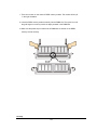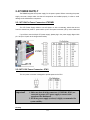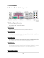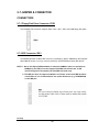
1
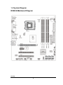
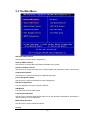
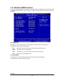
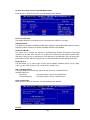
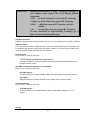
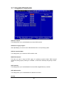
RX965Q User’s Manual Revision 1.0 http://www.bcmcom.com Rights: Declaration No part of this manual, including but not limited to the products and software described in it, may be reproduced, transmitted, transcribes, stored in a retrieval system, or translated in any form or by any means without the expressed written permission from the manufacturer. Products and corporate names appearing in this manual may or may not be registered trademarks or copyrights of their respective companies and are used only for identification or explanation purposes without intent to infringe. l Pentium M are registered trademarks of Intel Corporation, . l Microsoft and Windows are registered trademarks of Microsoft Corporation. l Phoenix and Award are registered trademarks of Phoenix Technologies LTD.. Responsibility: This manual is provided “As-Is” with no warranties of any kind, either expressed or implied, including, but not limited to the implied warranties or conditions of this product’s fitness for any particular purpose. In no event shall we be liable for any loss of profits, loss of business, loss of data, interruption of business, or indirect, special, incidental, or consequential damages of any kind, even the possibility of such damages arising from any defect or error in this manual or product. We reserve the right to modify and update the user manual without prior notice. WARNING: Replace the system’s CMOS RAM battery only with the identical CR-2032 3V Lithium-Ion coin cell (or equivalent) battery type to avoid risk of personal injury or physical damage to the equipment. Always dispose of used batteries according to the manufacturer’s instructions, or as required by the local ordinance (where applicable). References: This manual is created and written by BCM Technical Dept., but not limited, to the information from the RX965Q External Production Specifications, and RX965Q Specifications. If any comments, suggestions, or errors on this manual, please write an e-mail to [email protected]. Compliance & Certificate C o m pl i an c e & C e r t i fi c at e ISO 9001 Certificate: This device was produced in our plant with advanced quality system certified by DNV QA Ltd. in according to ISO 9001. This Certificate is valid for: DESIGN & MANUFACTURE OF MOTHERBOARD AND PERSONAL COMPUTERS. CE Declaration: CE marking is a visible declaration by the manufacturer or his authorized representatives that the electrical equipment to which it relates satisfies all the provisions of the 1994 Regulations. FCC Compliance: FCC stands for Federal Communications Commission. This product complies with FCC Rules Part 15 and has been tested, and complied with the EMI rules by a certified body. In normal operation, there shall be no harmful interference caused by this device nor shall this device accept any interference received, including interference that may cause undesired operation of this product. TABLE OF CONTENT MANUAL REVISION INFORMATION 1 ITEM CHECK LIST 1 CHAPTER 1 1-1 1-2 1-3 2 2 3 4 INTRODUCTION FEATURES OF RX965Q SPECIFICATION RX965Q MAINBOARD DIAGRAM CHAPTER 2 2-1 2-2 2-3 2-4 2-5 HARDWARE INSTALLATION HARDWARE INSTALLATION STEPS THE JUMPER/ CONNECTOR LOCATION INSTALL CPU INSTALL DDRII MEMORY MODULE POWER SUPPLY 2-5-1 ATX 20-PIN POWR CONNECTOR: ATX1 2-5-2 ATX 12V POWER CONNECTOR: JPW1 2-6 BACK PANEL 2-6-1 MOUSE/KEYBOARD CONNECTOR 2-6-2 VGA PORT 2-6-3 PARALLEL PORT 14 2-6-4 SERIAL PORTS 2-6-5 USB PORTS 2-6-6 LAN (RJ-45) JACKS 2-6-7 AUDIO PORT CONNECTORS 2-7 JUMPER AND CONNECTOR 2-7-1 FLOPPY DISK DRIVE CONNECTOR:FDD1 2-7-2 IDE CONNECTOR: IDE1 2-7-3 SERIAL ATAII CONECTORS: SATA1~ SATA2 2-7-4 FAN POEWR CONNECTORS: CPUFAN1/ SYSFAN1/ PWRFAN1 2-7-5 CD-IN CONNECTOR: CD_IN1 2-7-6 FRONT PANEL AUDIO CONNECTOR: JAUD1 2-7-7 SPDIF-OUT CONNECTOR: JSPD1 (OPTIONAL) 2-7-8 CHASSIS INTRUSION SWITCH CONNECTOR: JCASE1 2-7-9 FRONT PANEL CONNECTOR: JFP1/ JFP2 2-7-10 FRONT USB CONNECTORS: JUSB2/JUSB3 (JUSB1 IS OPTIONAL) 2-7-11 SERIAL PORT CONNECTOR: JCOM1 2-7-12 JSPI DEBUGGING PIN HEADER: JSPI1 2-7-13 CLEAR COMOS JUMPER: JBAT1 2-8 INSTALL PCI CARD 2-8-1 PROCEDURE FOR PCI CARD INSTLLATION 2-8-2 PCI EXPRESS SLOTS 2-8-3 PCI SLOTS 2-8-4 PCI INTERRUPT REQUEST ROUTING 2-9 STARTING UP THE SYSTEM CHAPTER 3 INTRODUCING BIOS 3-1 ENTERING SETUP 3-2 GETTING HELP 5 5 6 7 11 13 13 13 14 14 14 14 14 15 15 16 16 17 17 17 18 18 18 19 20 20 20 21 22 22 22 22 23 24 25 25 26 3-3 3-4 3-5 3-6 3-7 3-8 3-9 3-10 3-11 3-12 THE MAIN MENU STANDARD CMOS FEATURES ADVANCED BIOS FEATURES ADVANCED CHIPSET FEATURES INTEGRATED PERIPHERALS POWER MANAGEMENT SETUP PNP/PCI CONFIGURATION H/W MONITOR LOAD OPTIMIZED DEFAULTS BIOS SETTING PASSWORD 27 29 32 34 36 40 44 47 49 50 Manual Revision Information Reversion 1.0 Revision History First Release Date May. 2007 Item Checklist R RX965Q board R RX965Q Quick Installation Guide R RX965Q User’s Manual on CD (Digital Format) R RX965Q Device Drivers on CD R 80 wire ATA66/100 IDE cable x1 R SATA cable x1 R SATA Power cable x1 R I/O Shield for RX965Q RX965Q 1 Chapter 1 Introduction 1-1 Features of RX965Q The RX965Q combines the high performance and exceptional value of Intel® Q965 chipset with a full-featured, new generation, industrial board. The Intel® Q965 chipset supports Intel® Core TM 2 Duo, Pentium 4, Pentium D and Celeron D processors in LGA 775 package. The RX965Q supports 800/667/533 MHz single-/dual channel DDR2 SDRAM (DDR2 800 supports up to 4GB, DDR2 667/533 support up to 8GB, 240pin/ 1.8V). It also provides onboard Intel® 82566 Ethernet controllers (supports 10/100/1000 Base-TX Ethernet), CRT video output, Audio Line-Out and 2 COM ports. Furthermore, the RX965Q also comes with four USB2.0 ports on back panel and two internal USB2.0 ports headers. This board met today’s market demand of low power consumption, for POS, Kiosk and embedded applications. The RX965Q provides six SATA ports, two PCI slots, one PCI Express x1 slot, and one PCI Express-16 slot. This Micro-ATX Board is suitable for all the industry applications, which also well support with the Windows® 2000/ XP and Linux operating systems. RX965Q does provide scalability with high reliability & Longevity for Embedded Application. It is a wise choice for today’s computing solution. RX965Q 2 1-2 Specification Spec Description Dimension Chipset - Micro-ATX form factor PCB size: (24.4cm x 24.4cm) - Intel Q965 GMCH Chipset - Intel ICH8DO Chipset - Intel® Core TM 2 Duo, Pentium 4, Pentium D, Celeron D CPU processors in LGA775 package Video Display Memory Socket Expansion Slot Integrate IDE SATA LAN On Board Audio I/O BIOS Power - Intel Q965 chipset - Supports video outputs from VGA output - One PCI Express x16 slot - Four 240-pin /1.8V DDRII slots - Supports DDRII 800/667/533 SDRAM (DDRII800 supports up to 4GB. DDRII 667/533 support up to 8GB) - Two 32-bit PCI slot - One PCI-Express x1 slot - One USB-to-IDE port by JMicron JMB20335 - supports USB to Ultra ATA 66 mode NOTE: This IDE port does not support installation of OS onto or boot From the IDE hard drive connected to it. It is recommended to use optical disk drives (e.g. CD/DVD-ROM) on this IDE port. - Six SATAII ports by Intel® ICH8DO - SATAII ports supports data transfer up to 300MB/s - One Intel 82566 Gigabit Ethernet LAN - Realtek ALC883 High Definition audio chip. - Flexible 8-channel audio - PS/2 keyboard and PS/2 mouse connectors - Floppy drive connector x1 - Parallel port x1, Serial port x2 (1 on back panel, 1 on header) - USB 2.0 connector x8, (4 on back panel, 4 on two headers) - Audio connector CD-In - Front panel audio connector - AMI BIOS - APM /ACPI compliant - ATX standard 24-pin power connector RX965Q 3 1-3 System Diagram RX965Q Mainboard Diagram RX965Q 4 Chapter 2 Hardware installation 2-1 Hardware installation Steps Before starting the system, it is recommended to complete the following steps: 1. Make sure mainrboard jumpers are set in proper position 2. Install CPU 3. Install CPU Heatsink (It is recommended to add proper amount of thermal compound between the CPU Heatsink and CPU) 4. Install System Memory 5. Install Expansion cards (If there is any) 6. Connect IDE and Floppy cables, Front Panel /Back Panel cables 7. Connect ATX Power cables 8. Power-On and Load Optimal settings under BIOS 9. Save the BIOS setting and reboot 10. Install Operating System 11. Install device drivers and Utility RX965Q 5 2-2 The Jumper/ Connector Location RX965Q 6 2-3 Install CPU This mainboard supports Intel® CoreTM 2 Duo, Pentium 4, Pentium D, and Celeron D processor in LGA 775 package. When you are installing the CPU, make sure to install the CPU heatsink to prevent overheating. Important! 1. Overheating will seriously damage the CPU and system. Always make sure that the CPU cooling fan and heatsink are installed properly in order to protect the CPU from overheating. 2. Make sure you apply an even layer of heatsink compound between the CPU and CPU heatsink to enhance heat dissipation. 3. While replacing the CPU, always turn-off the ATX power supply or unplug the power supply’s power cord from the electric outlet first in order to ensure the safety of CPU. RX965Q 7 NOTE: When you are installing the CPU, make sure the CPU has a heatsink (with cooling fan) attached on its top to prevent overtheating. It is strongly recommended to apply an even layer of thermal compound between the CPU and CPU heatsink for better heat dispassion. Follow the steps below to install the CPU and CPU heatsink correctly: Important! 1. Do not touch the CPU socket pins to avoid damage to the socket. 2. Make sure the CPU heatsink is installed properly before turn-on the system. RX965Q 8 RX965Q 9 Important! Be sure there is sufficient air circulation across the CPU heatsink and Chassis FAN is functioning correctly. Otherwise, it may cause the CPU and mainboard overheated and become damaged. Install additional auxiliary cooling fan in the system chassis, if necessary. RX965Q 10 2-4 Install DDRII Memory Module The RX965Q provides four 240-pins non-ECC DDRII 800/ 667/ 533 DIMM slots, which supports the total memory size up to 4GB for DDRII 800, or up to 8GB for DDRII 667/533. Since DDRII modules are not interchangeable with DDRI modules, and DDRII standard is not backward compatible with DDRI, only DDRII memory module is allowed to be installed in DIMM slots (“DIMM_A1”, “DIMM_A2”, “DIMM_B1”, and “DIMM_B2”). Otherwise, the system won’t be able to boot up and mainboard might be damaged. Important! 1.In dual-channel mode, make sure to install pair(s) of memory modules in the same type and density at DDR DIMM slots in the arrangement like one of the three “Dual Channel Memory Population Rules” shown above. 2.To ensure system boot up successfully, always insert one of the memory modules at “DIMM_A1” slot. RX965Q 11 1. There is one notch on the center of DDRII memory module. The module will only fit in the right orientation. 2. Insert the DDRII memory module vertically into the DIMM slot. Then push it in until the gold fingers on memory module is deeply inserted in the DIMM slot. 3. Make sure the plastic clips on both ends of DIMM slot are locked on the DDRII memory module securely. RX965Q 12 2-5 POWER SUPPLY The RX965Q supports ATX power supply for the power system. Before connecting the power supply connector, always make sure that all components are installed properly in order to avoid damage to the mainboard or component. 2-5-1 ATX 24-Pin Power Connector: ATXPWR1 The ATX Power Supply allows to use soft power on with a momentary switch that connect from the chassis front panel to “power switch” pins of front panel connector (JFP1) on the mainboard. If you’d like to use the 20-pin ATX power supply, please plug in the power supply aligned with pin-1 and pin-13 (refer to the image shown below). 2-5-2 ATX 12V Power Connector: JPW1 This 12V power connector is designed to provide power to the CPU. Important! 1. Make sure that all of the connectors (ATXPWR1, JPW1) are connected to proper ATX power supply to ensure stable operation of the mainboard. 2. 450 Watts power supply (or above) is highly recommended for system stability. RX965Q 13 2-6 BACK PANEL The Back Panel Provides the following connectors: 2-6-1 Mouse/ Keyboard Connector: The connector for PS/2® mouse, PS/2® keyboard. 2-6-2 VGA Port: The DB 15-pin D-Subminiature female connector is provided for CRT monitor. 2-6-3 Parallel Port: A parallel port is a standard printer port that supports Enhanced Parallel Port (EPP) and Extended Capabilities Parallel Port (ECP)mode. 2-6-4 Serial Ports: The serial port is a 16550A high speed communication port that send/receive 16 byte FIFOs. You can attach a serial mouse or other serial devices directly to this connector. 2-6-5 USB Ports: The OHCI (Open Host Controller Interface) Universal Serial Bus port is designed for connecting USB devices such as USB keyboard, USB mouse, or other USB-compatible devices. 2-6-6 LAN (RJ-45) Jacks: RX965Q 14 The standard RJ-45 jack is provided for Local Area Network (LAN) connection. 2-6-7 Audio Port Connectors: The audio connectors are used for audio devices. RX965Q 15 2-7 JUMPER & CONNECTOR CONNECTORS 2-7-1 Floppy Disk Drive Connector: FDD1 This standard FDD connector supports 360k, 720k, 1.2M, 1.44M, and 2.88M floppy disk types. 2-7-2 IDE Connector: IDE1 The RX965Q provides a USB to IDE connector (controlled by JMicron JMB20335) that supports Ultra DMA 66 function. You may connect hard drives, CD/DVD-ROM and other IDE devices. NOTE: 1. Due to Full Speed USB bandwidth is limited to 480Mbit/s (which is equivalent to 60MByte/s), this IDE port cannot support Ultra DMA 100 transfer rate, or IDE devices designed to be operated at Ultra DMA 100 mode only. 2. This IDE port does not support installation of OS onto or boot from IDE hard drive connected to it. It is recommended to use optical disk drives (e.g. CD/DVD-ROM) on this IDE port. RX965Q 16 2-7-3 Serial ATAII Connectors: SATA1~ SATA6 SATA1/SATA2 are dual high-speed Serial ATAII interface ports. Each supports data transfer rate up to 300MB/s. These two connectors are fully compliant with Serial ATA specification. Each Serial ATA connector can connect to 1 SATA hard drive. 2-7-4 Fan Power Connectors: CPUFAN1/ SYSFAN1/ PWRFAN1 The Fan Power Connectors supports system cooling fan with +12V. When connecting the wire to the connectors, always take note that the red wire is the positive and should be connected to “+12V” pin; the black wire is designated for Ground and should be connected to “GND” pin. WARNING! Be sure there is sufficient air circulation across the processor’s heatsink and Chassis FAN is working correctly. Otherwise, it may cause the processor and mainboard overheat and damage. Install additional auxiliary cooling fan in the system chassis, if necessary. 2-7-5 CD-IN Connector: CD_IN1 This connector provided CD-ROM audio connection. RX965Q 17 2-7-6 Front Panel Audio Connector: JAUD1 The JAUD1 front panel audio connector provides connection to the front panel audio. It is compliant with Intel® Front Panel I/O Connectivity Design Guide. 2-7-7 SPDIF-Out Connector: JSPD1 (Optional) This connector provided connection to SPDIF (Sony & Philips Digital Interconnect Format) interface for digital audio transmission. 2-7-8 Chassis Intrusion Switch Connector: JCASE1 This connector connects to a 2-pin chassis switch. If the chassis is opened, the switch will be shorted and the buzzer will sound the alarm. The system will record this status and show a warning message on the screen. To clear the warning, you must enter the BIOS utility and clear the record. RX965Q 18 2-7-9 Front Panel Connector: JFP1/ JFP2 The RX965Q provides two front panel connectors for electrical connection to the front panel switches and LEDs. The JFP1 is compliant with Intel® Front Panel I/O Connectivity Design Guide. RX965Q 19 2-7-10 Front USB Connectors: JUSB2/JUSB3 (JUSB1 is optional) The RX965Q provides two standard USB 2.0 headers that are compliant with Intel I/O Connectivity Design Guide. USB 2.0 technology increases data transfer rate up to a maximum throughput of 480Mbps, which is 40 times faster than the USB1.1, and is ideal for connecting highspeed USB peripherals such as USB HDD, digital cameras, MP3 players, printers, modems. NOTE: Be sure “VCC” and “GND” signals are connected to the right pins in order to avoid possible damage. 2-7-11 Serial Port Connector: JCOM1 The RX965Q provides one 9-pin header as serial port (JCOM1). This port is a 16550A high speed communication port which send/receive 16 bytes FIFOs. You can attach a serial mouse or other serial devices to it. 2-7-12 JSPI Debugging Pin Header: JSPI1 The pin header is for internal debugging only. RX965Q 20 JUMPER 2-7-13 Clear CMOS Jumper: JBAT1 There is a CMOS RAM onboard which has a power supply from external battery to maintain the system configuration data. When it is necessary to clear the system configuration, use Clear CMOS jumper (JBAT1) to clear data. Follow the instructions below to clear the data: NOTE: The CMOS can be cleared by shorting pin 2-3 for at least 30 seconds while the system is OFF. Then return the pin connector back to pin 1-2. Avoid clearing the CMOS while the system is on, this may damage the mainboard. RX965Q 21 2-8 Install PCI card Important! Turn off system power when adding or removing PCI card or other component from the system. Failure to do so may cause severe damage to the mainboard and PCI card. 2-8-1 Procedure For PCI Card Installation 1. Read the documentation for the PCI card and make any necessary hardware setting for PCI card such as jumpers. 2. Align the card’s connectors and press it into the PCI slot firmly. 3. Set up the BIOS if necessary. 4. Install the software driver for installed PCI card that is provided by the PCI card manufacturer. 2-8-2 PCI Express Slots PCI Express architecture provides a high performance I/O infrastructure for desktop platforms with transfer rates starting at 2.5Giga transfers per second over a PCI Express X1 lane for Gigabit Ethernet, TV Tuners, 1394 controllers, and general purpose I/O. In addition, desktop platforms with PCI Express architecture will be designed to deliver highest performance in video, graphics, multimedia and other sophisticated applications. Moreover, PCI Express architecture provides a high performance graphics infrastructure for desktop platforms doubling the capability of existing AGP 8x designs with transfer rates of 4.0 GB/s over a PCI Express x16 lane for graphics controllers, while PCI Express x1 supports transfer rate of 250MB/s. 2-8-3 PCI Slots The PCI slots support LAN cards, SCSI cards, USB cards, and other add-on cards that comply with PCI specifications. At 32 bits and 33MHz, it yields a throughput rate of 133MBps. RX965Q 22 2-8-4 PCI Interrupt Request Routing The IRQ, acronym of interrupt request line, are hardware lines over which devices can send interrupt signals to the microprocessor. The PCI IRQ pins are typically connected to the PCI bus pins as follows: IMPORTANT! If install PCI card on shared PCI slot, make sure that the PCI card driver supports “Shared IRQ” or the card doesn’t need IRQ assignment. Otherwise, conflicts will arise between two PCI groups that will make the system unstable or the PCI card inoperable. RX965Q 23 2-9 Starting Up the system 1. After all connection is made, close the computer case cover. 2. Be sure all the switch are off, and check that the power supply input voltage is set to the local voltage, usually the input voltage is 220V∼240V or 110V∼120V which depending on where the country’s voltage used. 3. Connect the power supply cord into the power supply located on the back of system case according to the system user’s manual. 4. Turn on the peripheral as following order: a. The monitor. b. Other external peripheral (Printer, Scanner, External Modem etc… ) c. The system power. For ATX power supplies, user needs to turn on the power supply and press the ATX power switch on the front side of the case. 5. The power LED on the front panel of the system case will light. The LED on the monitor may light up or switch between orange and green after the system is on. If it complies with green standards or if it is has a power standby feature. The system will then run power-on test. While the test is running, the BIOS will alarm beeps or additional message will appear on the screen. If user does not see any thing within 30 seconds from the time power on the system. The system may have failed on power-on test. Recheck the jumper settings and connections or call the retailer for assistance. Beep Meaning One short beep when displaying logo No error during POST Long beeps in an endless loop No DRAM install or detected One long beep followed by three short Video card not found or video card memory bad beeps 6. High frequency beeps when system is CPU overheated working System running at a lower frequency During power-on, press <Del> key to enter BIOS setup. Follow the instructions in BIOS SETUP. 7. Power off the system: User must first exit or shut down the operating system before switch off the power switch. For ATX power supply, user can press ATX power switching after exiting or shutting down the operating system. If user uses Windows 9X, click “Start” button, click “Shut down” and then click “Shut down the computer?” The power supply should turn off after windows shut down. RX965Q 24 Chapter 3 Introducing BIOS The BIOS is a program located on a Flash Memory on the motherboard. This program is a bridge between motherboard and the operating system. When user starts the computer, the BIOS program gain control. The BIOS first operates a self-diagnostic test called POST (Power On Self Test) for all the necessary hardware, it detects the entire hardware device and configures the parameters of the hardware synchronization. Only when these tasks are completed done it gives up control of the computer to operating system (OS). Since the BIOS is the only channel for hardware and software to communicate, it is the key factor for system stability, and in ensuring that the system performance as its best. IMPORTANT! The items under each BIOS category described in this chapter are under continuous update for better system performance. Therefore, the description may be slightly different from the latest BIOS and should be held for reference only. 3-1 Entering Setup Power on the system and by pressing <Del> immediately allows user to enter BIOS Setup menu. If the message disappears before user respond and user still wish to enter Setup, restart the system to try again by turning it OFF then ON or pressing the “RESET” button on the system case. User may also restart by simultaneously pressing <Ctrl>, <Alt> and <Delete> keys. There are several options available in the BIOS Setup main menu, which will be explained in the following pages of this chapter. Here are some function keys that may be useful: RX965Q 25 3-2 Getting Help After entering the Setup menu, the first menu you will see is the Main Menu. Main Menu The main menu lists the setup functions you can make changes to. You can use the arrow keys (??) to select the item. The online description of the highlighted setup function is displayed at the bottom of the screen. Sub-Menu If you find a right pointer symbol (as shown in the image below) appears to the left of certain fields that means a sub-menu can be launched from this field. A sub-menu contains additional options for a field parameter. You can use arrows keys (??) to highlight the field and press <Enter> to call up the sub-menu. Then you can use the control keys to enter values and move from field to field within a sub-menu. If you want to return to the main menu, just press the <Esc> General Help <F1> The BIOS setup program provides a general help screen. You can call up this screen from any menu by simply pressing <F1>. The help screen lists the appropriate keys to use and the possible selections for the highlighted item. Press <Esc> to exit the help screen. RX965Q 26 3-3 The Main Menu Standard CMOS Features Use this Menu for basic system configurations. Advanced BIOS Features Use this menu to set the Advanced Features available on the system. Advanced Chipset Features Use this menu to change the values in the chipset registers and optimize the system’s performance. Integrated Peripherals Use this menu to specify the settings for integrated peripherals. Power Management Setup Use this menu to specify the settings for power management. PNP/PCI configurations This entry appears if the system supports PNP/PCI. H/W Monitor This entry shows the PC health status. Load Optimized Defaults Use this menu to load the BIOS default values set by the mainboard manufacturer specifically for optimal performance of the mainboard. BIOS Setting Password Use this menu to set the password for BIOS. RX965Q 27 Save & Exit Setup Save CMOS value changes to CMOS and exit setup. Exit Without Saving Abandon all changes and exit setup. RX965Q 28 3-4 Standard CMOS Features The items in Standard CMOS Features Menu includes some basic setup items. Use the arrow keys to highlight the item and then use the <PgUp> or <PgDn> keys to select the value that you want in each item. Date (MM:DD:YY) This allows you to set the system to t eh sate that you want (usually the current date). The format is <day><month><date><year>. Day Day of the week, from Sun to Sat, determined by BIOS. Read-only. Month The month from Jan. through Dec. Date The date from 1 to 31 can be keyed by numeric function keys. Year The year can be adjusted by user. Time (HH:MM:SS) This allows you to set the system time that you want (usually the current time). The time format is <hour><minute><second>. RX965Q 29 Primary/ Secondary/ Third/ Fourth IDE Master/ Slave Press <Enter> to enter the sub-menu, and the following screen appears: Device/ Vender/ Size It will display the device information that are connected to the IDE/SATA connector. LBA/Large Mode This allows you to enable or disable the LBA mode. Setting to Auto enables LBA mode if the device supports it and the devices is not already formatted with LBA mode disabled. Hard Disk S.M.A.R.T This allows you to activate the S.M.A.R.T. (Self-Monitoring Analysis & Reporting Technology) capability for the hard disks. S.M.A.R.T is a utility that monitors your disk status to predict hard disk failure. This gives you an opportunity to move data from a hard disk that is going to fail to a safe place before the hard disk that is going to fail to a safe place before the hard disk becomes offline. Floppy Drive A This item allows you to set the type of floppy drives installed. Available options: [none], [360k, 5.25in.], [1.2M, 5.25in.],[720k, 3.5in], [1.44M, 3.5in.], [2.88M, 3.5in.]. Halt on Keyboard Error The setting determines whether the system will stop if an error is detected at boot. Available options are: [No Errors] The system doesn’t stop for any detected error. [All, But Keyboard] The system doesn’t stop for a keyboard error. System Information Press <Enter> to enter the sub-menu, and the following screen appears: RX965Q 30 This sub-menu shows the CPU information, BIOS version and memory status of your system (read only). RX965Q 31 3-5 Advanced BIOS Features Quick Boot Setting the item to [Enabled] allows the system to boot within 10 seconds since it will skip some check items. Boot to OS/2 This allows you to run the OS/2® operating system with DRAM larger than 64MB. When you choose [NO], you cannot run the OS/2® operating system with DRAM larger than 64MB, but is is possible if you choose [YES]. Boot Sector Protection This item allows you to choose the virus warning feature for Hard Disk boot sector protection. If this function is enabled and someone attempt to write data into this area, BIOS will shows a warning message on screen and alarm beeps. Hyper-Threading Function The processor uses Hyper-Threading technology to increase transaction rates and reduces end-user response times. The technology treats the two cores inside the processor as two logical processors that can execute instructions simultaneously. In this way, the system performance is highly improved. If you disable the function, the processor will use only one core to execute the instructions. Note: Please disable this option if your operating system doesn’t support HT function, or unreliability and instability may occur. RX965Q 32 IMPORTANT! Enabling the functionality of Hyper –Threading Technology for your computer system requires ALL of the following platform Components: * CPU: An Intel® Pentium 4 Processor with HT Technology. * Chipset: An Intel® Chipset that supports HT Technology. * BIOS: A BIOS that supports HT Technology and has it enabled. * OS: An operating system that supports HT Technology. For more information on Hyper-threading Technology, go to http://www.intel.com/info/hyperthreading Hardware Prefetcher Enable this option will improve the performance of CPU. It is only available when P4 CPU is installed. IOAPIC Function This field is used to enable or disable the APIC (Advanced Programmable Interrupt Controller). Due to compliance with PC2001 design guide, the system is able to run in APIC mode. Enabling APIC mode will expand available IRQ resources for the system. Boot Sequence Press <Enter> to enter the sub-menu: 1st /2nd/3rd Boot Device & Boot From Other Device This options allows you to set the sequence of boot devices where BIOS attempts to load the disk operating system. Intel AMT Configuration (Optional, only for ICH8DO) Press <Enter> to enter the sub-menu: Intel AMT Support The items allow you to enable/ disable the AMT (Active Management Technology) support. Force IDER IDER (IDE redirection) enables the ability to boot system from a network location. Trusted Computing Press <Enter> to enter the sub-menu: TCG/TPM Support This option allows you to enable/disable the TPM (Trusted Platform Module) (1.1/1.2) support. RX965Q 33 3-6 Advanced Chipset Features Configure DRAM Timing by SPD The system board designer must select the proper value for this field, according to the specifications of the installed DRAM chips. When disabled, you can select the DRAM timing type. Memory Hole In order to improve performance, certain space in memory can be reserved for ISA peripherals. This memory must be mapped into the memory space below 16MB. When this area is reserved, it cannot be cached. Memory Remap Feature This field allows you to remap the memory which as PCI resources. DVMT Mode Select This field allows you to select the DVMT mode. Dynamic Video Memory Technology 3.0 (DVMT 3.0) allows additional memory to be allocated for graphics usage based on application need. DVMT/ FIXED Memory This field specifies the size of system memory allocated for video memory. “Fixed” mode is nonRX965Q 34 contiguous pagelocked memory allocated during driver initialization to provide a static amount of memory. “DVMT” mode is memory that is dynamically allocated based on memory requests made by application and are release back to the system once the requesting application has been terminated. ME-HECI This field allows you to enabled/disable ME-HECI. ME-IDER This field allows you to enable/disable ME-IDER. ME-KT This field allows you to enable/disable ME-KT. RX965Q 35 3-7 Integrated Peripherals USB 2.0 Controller This setting allows you to enable/disable the onboard USB controller. USB Device Legacy Support Select [Enabled] if you need to use a USB-interfaced device in the operating system. USB 2.0 Controller Mode This setting allows you to select the USB controller mode. BIOS EHCI Hand-off This item can used to stop the EHCI legacy for operations systems without EHCI hand-off mechanism loading properly. Setting it to “Disabled” to force EHCI ownership change Rely on EHCI driver. GbE Controller This setting allows you to enable/disable the onboard GbE (Gigabit Ethernet) controller. GbE LAN Controller This setting allows you to enable/disable the network boot function. RX965Q 36 Onboard 1394 (Optional) This item allows you to enable/disable the onboard IEEE 1394 controller. Audio Controller This setting is used to enable/disable the onboard audio controller. SATA Device Configuration Press <Enter> to enter the sub-menu and the following screen appears: SATA#1 Configuration It allows you to configure the SATA#1 controller. Available settings are: [Disabled] Disable the SATA devices. [Compatible] Enable the SATA devices and release the IRQ14/15 for SATA devices. [Enhanced] Select Enhanced if you want to use the SATA as IDE/RAID or AHCI function. Configure SATA#1 as When this option is set to [Enhanced], the field is adjustable. It allows user to configure the SATA device as IDE/ AHCI or RAID. SATA#2 Configuration When this option is set to [IDE], the field is adjustable. It allow you to enable/ disable the SATA#2 controller (SATA5, and SATA6). RX965Q 37 IDE Device Configuration Press <Enter> to enter the sub-menu and the following screen appears: PCI IDE BusMaster Set this option to [Enable] to specify that the IDE controller on the PCI local bus has bus mastering capability. I/O Device Configuration Press <Enter> to enter the sub-menu and the following screen appears: Onboard Floppy Controller Select [Enabled] if your system has a floppy drive installed on the system board and you wish to use it. If you install add-on FDC or the system has no floppy drive, select [Disabled] in this field. COM Port 1/ 2 Select an address and corresponding interrupt for the serial port 1/ 2. Parallel Port There is a built-in parallel port on the onboard super I/O chipset that provides “standard , ECP, and EPP features. It has the following options: [Disabled] [3BC] Line Printer port 0 [278] Line Printer port 2 [378] Line Printer port 1 RX965Q 38 Parallel Port Mode [Normal] Standard Parallel Port [EPP] Enhanced Parallel Port [ECP] Extended Capability Port [ECP+EPP] Extended Capability Port + Enhanced Parallel Port [Bi-Directional] To operate the onboard parallel port as Standard Parallel Port only, choose [SPP]. To operate the onboard parallel port in the EPP mode simultaneously, choose [EPP]. By choosing [ECP], the onboard parallel port will operate in ECP mode only. Choosing [ECP+EPP] will allow the onboard parallel port to support both the ECP and EPP modes simultaneously. Parallel Port IRQ This item allows you to set parallel port IRQ. RX965Q 39 3-8 Power Management Setup Energy Lake Feature (Optional, only available for ICH8DH) This item allows you to enable Intel’s “Energy Lake” Technology which can support Viiv feature to turn-on the turn-off the computer instantly. ACPI Function This option is designed to activate the ACPI (Advanced Configuration and Power Management Interface) function. If your operating system is ACP supported, such as Win2k/XP, select [Yes] to enable this function. ACPI Standby State This item specifies the power saving modes for ACPI function. If your operating system supports ACPI, such as Win2k/XP, you can choose to enter the Standby mode in S1(POS) or S3(STR) fashion through the setting of this field. The following are the available settings: [S1/POS] The S1 sleep mode is a low power state. In this state, no system context is lost (CPU or chipset) and hardware maintains all system context. RX965Q 40 [S3/STR] The S3 sleep mode is a lower power state where the information of system configuration and open applications/files is saved to main memory that remains powered while most of other hardware components turn off to save energy. The information stored in memory will be used to restore the system when a “wake up” even occurs. Re-Call VGA BIOS From S3 When ACPI Standby State is set to [S3/STR], users can select the options in this field. Selecting [Yes] allows BIOS to call VGA BIOS to initialize the VGA card when system wakes up (resumes) from S3 sleep state. The system resume time is shortened when you disable the function, but system will need an VGA driver to initialize the VGA card. Therefore, if the VGA driver of the card does not support the initialization feature, the display may work abnormally or not function after resuming from S3. Suspend Time Out (Minute) If system activity is not detected for the length of time specified in this field, all devices except CPU will be shut off. Power Button Function This feature sets the function of the power button. Settings are: [On/ Off] The power button functions as normal power off button. [Suspend] When you pressed the power button, the computer enters the suspend/sleep mode, but if the button is pressed for more than four seconds, the computer is turned off. Restore On AC Power Loss This item specifies whether your system will reboot after a power failure or interrupt occurs. Settings are: [Power Off] Always leaves the computer in the power off state. [Power On] Always leaves the computer in the power on state. [Last State] Restores the system to the status before power failure or interrupt occurred. RX965Q 41 Wakeup Event Setup Press <Enter> and the following sub-menu appears: USB Device Wakeup From S3/S4 This item allows the activity of the SUB device to wake up the system from S3/S4 states. S3 Power on by PS/2 KB This option specifies how the system will be awakened from power saving mode when input Signal of the PS/2 keyboard is detected. Use <Page Up> & <Page Down> keys to select the options. When selecting [password], enter the desired password. S3 Power On by PS/2 Mouse This setting determines whether the system will be awakened from S3 when input signal of PS/2 mouse is detected. GbE Wake Up From S5 An input signal on LAN awakens the system from S5. Resume by RTC Alarm This field is used to enable or disable the feature of booting up the system on a scheduled time/date. Resume by PCI Device (PME#) When setting to [Enabled], this setting allows your system to be awakened from the power saving modes through any event on PME (Power Management Event). Date (of Month) Alarm This field specifies the date for Resume by RTC Alarm. RX965Q 42 Time (HH:MM:SS) Alarm This field specifies the time for Resume by RTC Alarm. Format is <hour> <minute> <second>. RX965Q 43 3-9 PNP/PCI Configuration This section describes configuring the PCI bus system and PnP (Plug & Play) feature. This section covers some technical items and it is strongly recommended that only experienced users should make any changes to the default settings in order to maintain the stability of system. Clear ESCD The ESCD (Extended System Configuration Data) NVRAM (Non-volatile Random Access Memory) is where the BIOS stores resource information for both PNP and non-PNP devices in a bit string format. When the item is set to [Yes], the system will reset ESCD NVBRAM right after the system is booted up and then set the setting of the item back to [No] automatically. Initate Graphic Adapter This setting specifies which graphic card will be designated as the primary graphic device. PCI Latency Timer This item controls how long each PCI device can hold the bus before another takes over. When set to higher values, every PCI device can conduct transactions for a longer time and thus improve the effective PCI bandwidth. For better PCI performance, you should set the item to higher values. RX965Q 44 PCI Slot 1/ 2 IRQ These items specify the IRQ line for each PCI slot. IRQ Resource Setup Press <Enter> to enter the sub-menu and the following screen appears: IRQ 3/ 4/ 5/ 7/ 9/ 10/ 11/ 14/ 15 These items specify the bus where the specified IRQ line is used. The settings determine if AMI BIOS should remove an IRQ from the pool of available IRQs passed to devices that are configurable by the system BIOS. The available IRQ pool is determined by reading the ESCD NVRAM. If more IRQs must be removed from the IRQ pool, the end user can use these settings to reserve the IRQ by assigning an [Reserved] setting to it. Onboard I/O is configured by AMI BIOS. All IRQs used by onboard I/O are configured as [Available]. If all IRQs are set to [Reserved], and IRQ 14/ 15 are allocated to the onboard PCI IDE< IRQ9 will be available for PCI and PnP devices. DMA Resource Setup Press <Enter> to enter the sub-menu and the following screen appears: RX965Q 45 DMA Channel 0/ 1/ 3/ 5/ 6/ 7 The settings determine if AMI BIOS should remove a DMA (Direct Memory Access) from the available DMAs passed to devices that are configurable by the system BIOS. The available DMA pool is determined by reading the ESCD NVRAM. If more DMAs must be removed from the pool, the end user can reserve the DMA. RX965Q 46 3-10 H/W Monitor Fan Speed Monitor 1/ 2/ 3 (Optional) This item allows you to enable/disable the FAN Speed monitors. AFSC Configuration (Optional) This item allows you to lock/unlock AFSC (Advanced Fan Speed Control) Configuration. AFSC SST BUS (Optional) This item allows you to lock/unlock AFSC SST (Simple Serial Transport) Bus. AFSC Sensor Thresholds (Optional) This item allows you to lock/unlock AFSC Sensor Thresholds. AFSC Manual Fan Ctrl (Optional) This item allows you to lock/unlock AFSC Manual Fan Controller. RX965Q 47 AFSC Chipset (Optional) This item allows you to lock/unlock AFSC Chipset. Thermal Sensor (Optional) This item allows you to display/hide the thermal sensor. CPU FAN TargetTemp Value (Optional) When the CPU temperature reaches a present limit, the CPU fan turns on. Chassis Intrusion The field enables or disables the feature of recording the chassis intrusion status and issuing a warning message if the chassis is once opened. To clear the warning message, set the field to [Reset]. The setting of the field will automatically return to [Enabled] later. == System Monitor == These items display the current status of all of the monitored hardware devices/ components such as CPU voltage, temperatures and all fans’ speeds. RX965Q 48 3-11 Load Optimized Defaults The option on the main menu allows users to restore all of the BIOS settings to the default optimized values. The optimized defaults are the default values set by the mainboard manufacturer specifically for optimal performance of the mainboard. When you select “Load Optimized Defaults”, a message as below appears: Press “Y” loads the default factory settings for optimal system performance. RX965Q 49 3-12 BIOS Setting Password When you select this function, a message as below will appear on the screen: Type in the password, up to six characters in length, and press <Enter>. The password types now will replace any previously set password from CMOS memory. You will be prompted to confirm the password. Retype the password and press <Enter>. You may also press <Esc> to abort the selection and not to enter a password. To clear a set password, just press <Enter> when you are prompted to enter the password. A message will show up confirming the password will be disabled. Once the password is disabled, the system will boot and you can enter setup without entering any password. When a password has been set, you will be prompted to enter it every time you try to enter setup. This prevents an unauthorized person from changing any part of your system configuration. RX965Q 50