1
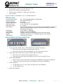
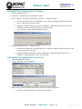
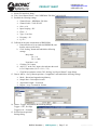
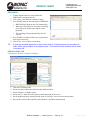
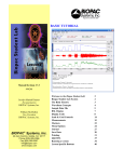
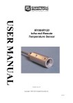
PRODUCT SHEET
[email protected]
[email protected]
www.biopac.com
NON-INVASIVE SMALL ANIMAL TAIL BLOOD PRESSURE SYSTEMS
NIBP250 Blood Pressure Amplifier
NIBP200A Blood Pressure System
NIBP Amplifiers with built-in pump automatically inflate the tail cuff to occlude the vessel in the tail of a rat or
similar small animal, and then slowly deflate the cuff when the inflation point is reached, providing a linear drop
in pressure. A single control starts both the inflation and deflation cycles, making the system very operatorfriendly. Amplifiers have two analog outputs for pressure and pulse waveforms, plus gain adjustment to amplify
or attenuate the pulse signal. Systolic, diastolic, and mean BP values.
NIBP250 Touchscreen LCD controls and displays data for local analysis and storage. Use as a standalone system or interface to BIOPAC or third-party A/D hardware. USB 1.1 compatible flash memory
port and SD card slot.
• NIBP200A Amplifier for use with Tail Cuff Sensor.
Systems include:
• Amplifier order NIBP250 or NIBP200A
• One tail cuff sensor (request size):
RXTCUFSENSOR9.5 = 9.5 mm, 100-220 g
RXTCUFSENSOR11 = 11 mm, 200-280 g
RXTCUFSENSOR13 = 13 mm, 250-350 g
• One small animal restrainer:
RXRESTRAINER-MICE, 10-25 g (mice)
RXRESTRAINER-S, 70-150 g (small rat)
RXRESTRAINER-M, 150-200 g (medium rat)
RXRESTRAINER-L, 250-350 g (large rat)
• Optional MRI-conditional sensors available – add to an existing NIBP200A system
RXCUFSEN9.5-MRI = 9.5 mm, 100-220 g
RXCUFSEN11-MRI = 11 mm, 200-280 g
RXCUFSEN13-MRI = 13 mm, 250-350 g
MRI Use:
MR Conditional
•
Condition:
Animal use only; tested to MR field strength 3T
RXTCUFSENSOR 9.5/11/13 Components—MRI chamber room components only:
Cable: Dual Fiber Optical Cable
Sensor Housing: Delrin®
Air Line: Tygon® Tubing
SensorType: Infrared
Sensor Tubing: Latex
BIOPAC Hardware | NIBP Systems | Page 1 - 10
Updated: 4.28.2015
PRODUCT SHEET
•
•
•
•
[email protected]
[email protected]
www.biopac.com
Analog outputs: pressure 0-3 V DC, Pulse 0-4 V DC
Output cables: pressure cable and pulse cable
Interface cables: to BIOPAC or third-party A/D hardware
User’s Manual
Optional Tail Heater: TAILHEATA 110 V or TAILHEATB 220 V
SPECIFICATIONS
Cut-off Pressure Range:
Pressure Accuracy:
Pressure Sensitivity:
Pressure Signal output:
Pulse Gain Levels:
Pulse Signal Output:
Pulse Display:
LCD Display:
User Interface:
Analog outputs:
Triggers:
Power Supply:
100 – 300 mmHg (adjustable by 1mmHg steps)
300 mmHg Full Scale 1%
0.1 mmHg
300 mmHg/3 Volt DC
x1, x2, x4, x5, x8, x16, x32 (adjustable)
0 – 4 Volt DC
Pulse intensity is displayed on A2, derived from plethysmographic measure The
tail sensor detects blood flow and pulse intensity is increased or decreased,
depending on the flow ratio.
7” 800 x 480 TFT (NIBP250)
Resistive Touch Panel (NIBP250)
Two BNC connectors for uncalibrated pressure and pulse signals
Two BNC connectors for TTL Compatible trigger in and out signals
12 Volt 2 Amp – External
NIBP200A/NIBP250 SYSTEM CONNECTIONS
NIBP200A Front Panel
NIBP200A Rear Panel
1. Connect the CBL150-PRE cable (or CBL35-PRE cable for MP36/35 hardware).
a. BNC to the PRESSURE output on the back panel of the unit.
b. Other end to A1 on the front of the UIM100C (or CH 1 of the MP36/35 unit).
2. Connect the CBL150-PLS cable (or CBL35-PLS for MP36/35 hardware).
a. BNC to the PULSE output on the back panel of the unit.
b. Other end to A2 on the front of the UIM100C unit (or CH 2 of the MP36/35 unit).
3. Connect the IRSENSOR.
a. Black cord to the sensor input on the front panel of the NIBP200A (back panel on NIBP250).
b. Tubing in the cuff on the front panel of the NIBP200A (back panel on NIBP250).
4. Connect the power.
a. AC300 adapter to the 12 V DC input on the back panel of the NIBP200A.
b. AC300 to Mains power.
5. Switch the POWER on.
BIOPAC Hardware | NIBP Systems | Page 2 - 10
Updated: 4.28.2015
[email protected]
[email protected]
www.biopac.com
PRODUCT SHEET
ANIMAL PREPARATION
Optional Heating Chamber
Restrainer Animal Holders
Tail Cuff/Sensor
1. Turn the Animal Heating Chamber on.
2. Set the temperature value (press and hold P.Set and then press the up or
down arrow to reach the desired value).
• For accurate noninvasive blood pressure measurement, the animal or
its tail should be warmed to 32° C.
3. Press the Heater button to start heating to the selected temperature value.
4. Place the animal inside the RESTRAINER “Animal Holder” (select the suitable size for the animal
volume).
• Leave the tail outside.
• Adjust the length to obtain a position where the animal has limited movement.
5. Place the RESTRAINER (with the animal) in the heating section of the Animal Heating Chamber.
6. Wait approximately 30 minutes for the animal to reach the selected temperature.
7. Remove the RESTRAINER from the Animal Heating Chamber.
8. Connect the IRSENSOR to the tail of the animal inside the RESTRAINER.
9. Check if the sensor just fits to the tail. The sensor should be between the mid point of tail and tail end
(spinal column). To achieve this, a suitable sensor should be selected.
10. Wait for the animal to relax and become inactive before starting measurements.
TIP
Before starting the experiment, to condition the animal, put the animal inside the holder several
times a day and repeat the heating each time.
BIOPAC Hardware | NIBP Systems | Page 3 - 10
Updated: 4.28.2015
PRODUCT SHEET
[email protected]
[email protected]
www.biopac.com
SOFTWARE SETUP (AcqKnowledge 4.1 and higher)
1. Launch AcqKnowledge 4.x.
2. Select the “Create/Record a new experiment” option.
3. Select “MP150 > Set Up Data Acquisition > Channels > “Add New Module...”
a. From the new module list, select UIM100C-A1 (or whichever channel CBL150-PRE pressure
cable is connected to) and click “Add.”
b. From the UIM100C Transducer list, select “NIBP200A – Small Animal Tail BP, Pressure” or
“NIBP250 – Small Animal Tail BP, Pressure” and click OK.
c. Click “Calibrate” in the resulting Calibration dialog.
4. Repeat “Add New Module…” portion of Step 3.
a. From the new module list, select UIM100C-A2 (or whichever channel CBL150-PLS pulse cable
is connected to) and click “Add.”
b. From the UIM100C Transducer list, select “NIBP200A – Small Animal Tail BP, Pulse” or
“NIBP250 – Small Animal Tail, Pulse” and click OK.
SOFTWARE SETUP (AcqKnowledge 4.0 and earlier)
1. Launch the BIOPAC software.
2. Choose “MP menu > Set up Channels.”
or
3. Enable analog inputs A1 and A2 and select the Acquire, Plot and Value options.
• If desired, enter channel Labels: A1 Pressure and A2 Pulse.
BIOPAC Hardware | NIBP Systems | Page 4 - 10
Updated: 4.28.2015
PRODUCT SHEET
[email protected]
[email protected]
www.biopac.com
4. Calibrate for the pressure measurement of IRSENSOR.
a. Select A1 (Pressure) and click Setup and establish these settings:
Input volts
Scale (Map) value
Cal 1
0
0
Cal 2
1
100
Units Label:
mmHg
The scaling must be adjusted as the cut-off
pressure switch settings are changed. If the
pressure switch is set to 300 mmHg, then the
settings should be:
Input volts
Scale (Map) value
Cal 1
0
0
Cal 2
3
300
Units Label:
mmHg
b. Click OK as needed to close out of A1 setup.
5. Calibrate for the pulse measurement of IRSENSOR.
a. Ensure that the tail is not inside the IRSENSOR and it is empty, and the sensor resides freely.
b. Select A2 (Pulse) and click Setup and establish these settings:
Input volts
Scale (Map) value
Cal 1
0
0
Cal 2
1
4
Units Label:
Volts
c. Click OK as needed to close out of A2 setup and the Setup Channels dialog.
6. Choose “MP menu > Set up Acquisition” and establish the following settings:
Mode = Record and Append to Memory
Sample Rate = 200 samples/second
Total Length = 24 seconds
Repeat = every 3 seconds for 10 times
7. Exit Set up Acquisition dialog.
BIOPAC Hardware | NIBP Systems | Page 5 - 10
Updated: 4.28.2015
PRODUCT SHEET
[email protected]
[email protected]
www.biopac.com
8. Choose “MP menu > Setup Trigger” and establish the following settings:
Trigger = CH 1, Pos Edge
Trigger Level = 0.33 Volts
(based on 1 V ≈ 100 mmHg)
Delay = 0 samples
9. Close out of Triggering dialog.
SOFTWARE SETUP for AcqKnowledge 4.x or BSL 4.x with MP3x Hardware
1. Launch the software.
2. Select the “Create/Record a new experiment” option.
3. If necessary, choose “MP3x > Set up Data Acquisition > Channels.”
4. Enable analog inputs CH1 and CH2 and select the Acquire, Plot and Value options.
5. Select CH1 and click “Setup.”.
6. Click “New Channel Preset,” enter “NIBP200A-Pressure” and click OK.
7. Establish the following settings:
• Channel Preset = NIBP200A-Pressure
• Channel Label = CUFF PRESSURE
• Gain = x10
• Input Coupling = DC
• Filter = 1
• Type = Low Pass
• Frequency = 30
• Q = 0.5
8. Calibrate for the pressure measurement of IRSENSOR.
a. Click “Scaling” button and establish the following settings:
Map values
Cal1 = 0
Cal2 = 100
Units label = mmHg
b. Click the Cal 1 button.
c. Add “333” to the Cal 1 Input value, and enter the result in
Cal 2 Input value (Cal 2 = Cal 1 + 333)
d. Click OK as needed to exit the CH1 “Scaling” and Input
“Channel” setup dialogs.
BIOPAC Hardware | NIBP Systems | Page 6 - 10
Updated: 4.28.2015
PRODUCT SHEET
[email protected]
[email protected]
www.biopac.com
9. Select CH2 and click “Setup.”
10. Click “New Channel Preset,” enter “NIBP200A-Tail Pulse” and click OK.
11. Establish the following settings:
• Channel Preset = NIBP200A-Tail Pulse
• Channel Label = TAIL PULSE
• Gain = x10
• Input Coupling = DC
• Filter = 1
• Type = Low Pass
• Frequency = 50
• Q = 0.5
12. Calibrate for the pulse measurement of IRSENSOR.
a. Ensure that the tail is not inside the IRSENSOR, and
that the sensor resides freely.
b. Click “Scaling” button and establish the following
settings:
Map values
Cal 1 = 0
Cal 2 = 1000
Units label = mV
c. Click the Cal 1 button.
d. Add “333” to the Cal 1 Input value and enter the result
in Cal 2 Input value (Cal 2 = Cal 1 + 333)
e. Click OK as needed to exit the CH2 “Scaling” and “Input Channel” setup dialogs.
13. Choose “MP3x > Set Up Data Acquisition > Length/Rate” and establish the following settings:
• Mode = Record and Append using Memory
• Sample Rate = 200 samples/second
• Acquisition Length = 24 seconds
• Repeat = every 3 seconds for 10 times
14. Choose “Trigger” and establish the following settings.
Trigger = CH 1, Pos Edge
Trigger Level = 30 mmHg
15. Exit the Data Acquisition
Settings dialog.
BIOPAC Hardware | NIBP Systems | Page 7 - 10
Updated: 4.28.2015
PRODUCT SHEET
[email protected]
[email protected]
www.biopac.com
RECORDING
1. Confirm that the animal is ready and that the
IRSENSOR is attached to the tail.
2. Click “Start” in the BIOPAC software window.
3. Press START button on the front panel of NIBP200A.
• IRSENSOR will pump up the Cuff automatically.
• When the Cuff Pressure on A1 reaches 30 mmHg,
the cuff pressure and tail pulse signals will be
generated.
• The recording will stop automatically after 24
seconds.
4. Press START to continue with the next measurement
and repeat as necessary.
5. Choose File > Save or Save as when done.
TIP
A generally accepted application is that for each animal, 10 measurements are recorded and
mean values are calculated. In the append mode, 10 consecutive measurements can be made
in the same file.
NIBP200A ANALYSIS
Calculation of Systolic, Diastolic and Mean.
1.
2.
3.
4.
5.
6.
Click the Calculation Label.
Select from the list Max, Min, Mean for three different Labels.
Select Channel 1 as channel option.
Select cursor ‘I’ from the cursor option on the bottom right of the screen.
On the graphical display, starting from the point of first pulse, select an area to the maximum.
Review the results for Max (Systolic), Min (Diastolic), and Mean measurements.
BIOPAC Hardware | NIBP Systems | Page 8 - 10
Updated: 4.28.2015
PRODUCT SHEET
[email protected]
[email protected]
www.biopac.com
Calculation of BPM Heart
1. Set a measurement for BPM.
2. Use the I-beam cursor to select the maximum points of the peaks of the CH2 pulse waveform.
3. Review the results for BPM (Heart Rate value) for each peak.
NIBP250 QUICK GUIDE
PREPARE
- With unit turned off, attach the sensor and cuff connectors.
- Turn on unit and wait for the Main Screen to appear.
- Prepare the animal and attach sensor-cuff to tail.
ACQUIRE
- When preparation is complete: Press the “Start” button on the Main Screen. The button label changes to “Stop”
and you can halt the acquisition at any time.
- When the acquisition starts, the unit automatically closes the leakage valve and begins inflating the cuff.
- After pressure reaches the maximum level, the pump stops and opens the leakage valve to release the pressure.
- After the pressure is fully released, the acquisition stops.
NIBP250 ANALYSIS
The NIBP250’s automated peak detection system marks the peak of each pulse with a white cross, and is enabled
by selecting the "Peak by peak" option on the Main Screen. This feature makes it easier to identify the individual
pulses. To determine the systolic and diastolic values:
1. Select the "Peak by peak" box on the main screen.
2. Use the right (or left) cursor button to locate the first pulse's white cross and press the "Systolic" button.
(You may also place the cursor using the touch screen.) The system will record and display the systolic
blood pressure value.
3. Use the cursor button (or touch screen) to move to the pulse with the highest peak and then press the
"Diastolic" button. The system will record and display the diastolic blood pressure value..
You may change your cursor peak positions at anytime during the analysis.
After measurement is complete, press the Save button under “Results.” An automatically generated result code
will be displayed at the top of the results section.
For analysis in BIOPAC AcqKnowledge or BSL PRO software, see previous page for NIBP200A.
BIOPAC Hardware | NIBP Systems | Page 9 - 10
Updated: 4.28.2015
PRODUCT SHEET
[email protected]
[email protected]
www.biopac.com
SAVE RESULTS
- Previously saved results can be displayed by pressing the “Load” button under “Results.”
- Placing the cursor on a desired measurement and pressing OK will load the recorded pressure, pulse curves and
previously calculated results.
- After loading is complete, you can easily evaluate the results and re-analyze any measurements.
TURN OFF
- Before turning off the unit, be sure that the current measurement was saved.
- Power off the unit by switching the power button on the back
TROUBLESHOOTING
Tail Pulse signals are not regular.
• The animal may be under stress, resulting in excessive tail movement. Remove the animal from the
RESTRAINER holder until it calms down before continuing with the experiment.
• The tail may not be sufficiently warmed or cooled down. Put the animal in the Tail Heater Chamber
and repeat the heating process. Make sure the tail temperature is 32° C.
• Tail Cuff sizing may be incorrect. Check Table 5 on the following page for sizing descriptions.
• Tail Cuff Sensor position may be incorrect. Try re-attaching the sensor in a different location on the
tail. The optimal location is between the mid-point of tail and base of tail (spinal column).
Compressor is working continuously.
• Immediately turn off the NIBP system.
• Remove the Tubing from the Cuff connector on the panel of NIBP system
• Turn the system back on.
• Close the air outlet by pressing the finger on the Cuff output and press the “Start” button. The
compressor will work for a few seconds and stop (please inform BIOPAC if the Compressor does not
stop). The pressure chart should be viewable on the screen.
• If the Compressor stops automatically, it means that the system is working normally.
There is leakage in the tubing connections and Cuff of the IRSENSOR.
• Make sure the tubing is securely attached.
BIOPAC Hardware | NIBP Systems | Page 10 - 10
Updated: 4.28.2015