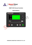
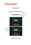
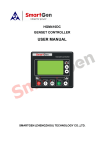
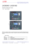
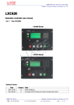
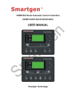
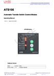
1
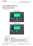
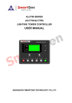
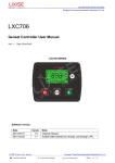
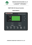
LXC31X0 Generator controller user manual
Dongguan Tuancheng Automation Equipment Co.,LTD.
LXC31X0
Series Genset Controller
LXC3110/LXC3120 User Manual
Ver1.1
Date: 2014/12/26
LXC31X0 Series
Software version
Date
2012-06-12
2014-12-26
Versio
n
1.0
1.1
Note
Original release.
Flywheel teeth configuration items increase:(When
genset has no magnetic sensor,please set to 5 to
close magnetic sensor)
LXC31X0 User Manual
�: T:+86
769-23162896
Dongguan Tuancheng Automation Equipment Co.,LTD.
�: F:+86 769-23166296
� :www.lixise.com
Page 1 of 28
LXC31X0 Generator controller user manual
Dongguan Tuancheng Automation Equipment Co.,LTD.
Clarification of notation used within this publication.
Symbol
NOTE
CAUTION
WARNING
Instruction
Highlights an essential element of a procedure to ensure correctness.
Indicates a procedure or practice, which, if not strictly observed, could result in
damage or destruction of equipment.
Indicates a procedure or practice, which could result in injury to personnel or
loss of life if not followed correctly.
LXC31X0 User Manual
�: T:+86-769-23836636
Dongguan Tuancheng Automation Equipment Co.,LTD.
�: F:+86-769-23166296
� :www.lixise.com
Page 2 of 28
LXC31X0 Generator controller user manual
Dongguan Tuancheng Automation Equipment Co.,LTD.
Contents
1. Summary................................................................................................................................................................. 4
2. Performance and characteristics.........................................................................................................................4
3. Specification........................................................................................................................................................... 5
4. Operation................................................................................................................................................................ 6
4.1. Push buttons............................................................................................................................................... 6
4.2. Indicator light............................................................................................................................................... 7
4.3. Automatic start/stop operation..................................................................................................................8
4.3.1. Auto Start Sequence,......................................................................................................................8
4.3.2. Auto Stop Sequence,......................................................................................................................8
4.4. Manual start/stop operation...................................................................................................................... 9
5. Protection................................................................................................................................................................ 9
5.1. Warnings......................................................................................................................................................9
5.2. Shutdown alarm........................................................................................................................................10
6. Connections..........................................................................................................................................................11
7. Parameters setting.............................................................................................................................................. 13
7.1. Password Management...........................................................................................................................13
7.2. Language...................................................................................................................................................14
7.3. Mode Select.............................................................................................................................................. 14
7.4. Definition and range of parameters....................................................................................................... 14
7.5. Programmable input 1-4 table (Active when connect GND (B-))...................................................... 19
7.6. Programmable output 1-5....................................................................................................................... 20
7.7. Sensor select............................................................................................................................................ 22
7.8. Conditions of crank disconnect.............................................................................................................. 22
7.9. Sensor select............................................................................................................................................ 23
7.10. Sensor unit conversion table................................................................................................................ 24
8. Commissioning.....................................................................................................................................................24
9. Typical application............................................................................................................................................... 25
10. Installation...........................................................................................................................................................26
10.1. Fixing clips...............................................................................................................................................26
10.2. Overall dimension and panel cutout....................................................................................................27
11. Fault finding........................................................................................................................................................28
12. Product packaging.............................................................................................................................................28
LXC31X0 User Manual
�: T:+86-769-23836636
Dongguan Tuancheng Automation Equipment Co.,LTD.
�: F:+86-769-23166296
� :www.lixise.com
Page 3 of 28
LXC31X0 Generator controller user manual
Dongguan Tuancheng Automation Equipment Co.,LTD.
1. Summary
LXC31X0 Series automation controller uses 32-bit ARM processor, the module is realized intelligent
generator control technology.There are used for genset automation and monitor control system of single
unit to achieve automatic start/stop, data measurement, alarm protection.It fit with LCD display, optional
languages interface (Chinese, English, Spanish and Russian), and it is reliable and easy to use.It’s
achieve a precision measuring,fixed value adjustment, time setting and set value adjusting and etc.All
parameters can be configured from front panel or through programmable USB interface via PC. It can
be widely use in all types of automatic genset control system with compact structure, advanced circuits,
simple connections and high reliability.
2. Performance and characteristics
LXC31X0 series controller has two types:
LXC3110:ASM (Automatic Start Module),it controls generator to start/stop by remote signal;
LXC3120:AMF (Auto Mains Failure), updates based on LXC3120, moreover, has mains electric quantity
monitoring and mains/generator automatic transfer control function, especially for automatic system
composed by generator and mains.
Its main features are as follows:
�
Display
Display:132×64 LCD with emerald green backlight;
�
Language
anguage:Chinese, English, Spanish and Russian;
�
Operating
Operating:good feeling button pushing, long button life;
�
Suitable for
for:3-phase 4-wire, 3-phase 3-wire, single phase 2-wire, and 2-phase 3-wire systems with
voltage 120/240V and frequency 50/60Hz.
� Detection parameters:
Mains
Line Voltage
Phase Voltage
Frequency
�
Gens
Line Voltage
Phase Voltage
Frequency
Uab,Ubc,Uca
Ua,Ub,Uc
Hz
Uab,Ubc,Uca
Ua,Ub,Uc
Hz
Load
Load:
Current
IA,IB,IC
Active Power
(KW)
Reactive Power
(KVar)
Apparent Power
(KVA)
Power Factor
(PF)
Accumulated Energy
(kWh)
�
Mains Monitor
Monitor:With over voltage, under voltage, over frequency, under frequency, loss phase and
reverse phase function;
�
ns Monitor
Ge
Gens
Monitor:With over voltage, under voltage, over frequency, under frequency, loss phase and
reverse phase function;
�
Acquisition parameters
parameters:
Temp. (WT)
°C/ °F both be displayed
LXC31X0 User Manual
�: T:+86-769-23836636
Dongguan Tuancheng Automation Equipment Co.,LTD.
�: F:+86-769-23166296
� :www.lixise.com
Page 4 of 28
LXC31X0 Generator controller user manual
Dongguan Tuancheng Automation Equipment Co.,LTD.
Oil pressure (OP)
kPa/Psi/Bar all be displayed
Engine Speed (RP)
RPM (Unit)
Battery Voltage (VB)
V (unit)
Charger Voltage (VD)
V (unit)
Hours counter (HC):
Max. 999999 hours
Start times:
Max.999999 times
�
Protection: Automatic start/stop of the genset, ATS(Auto Transfer Switch) control with perfect fault
indication and protection function;
�
Output Control
Control:With ETS, idle control, pre-heat control, speed raise control and speed drop control,
All output ports are relay-out;
�
Parameter Settings
ettings:All the parameters can be adjusted using front panel of the controller or use the
computer through USB to connect directly to controller settings, all is not lost when power down
parameter system;
�
Sensor Detection
etection:More kinds of curves of temperature, oil pressure, fuel level can be used directly
and users can define the sensor curves by themselves;
�
Gens frequency,speed,oil pressure,D+
Multiple Crank Disconnect Conditions
onditions:Gens
pressure,D+;
�
range:: DC(8~35)V, suitable to different start battery voltage environment;
Widely Power supply range
�
Mounting Assembly
ssembly:Modular design, anti-flaming ABS plastic enclosure, plug gable connection
terminals and embedded installation way; compact structure with easy mounting.
3. Specifica
Specificattion
Items
Working Voltage
Contents
DC8. 0V to 35. 0V, Continuous Power Supply.
Overall Consumption
<3W(Standby mode: ≤2W)
AC voltage Input:
3 Phase 4 Wire
2 Phase 3 Wire
Single phase 2 Wire
3 Phase 3 Wire
Alternator Frequency
15V AC - 360 V AC (ph-N)
15V AC - 360 V AC (ph-N)
15V AC - 360 V AC (ph-N)
30V AC - 620 V AC (ph-ph)
50 Hz /60Hz
Speed Sensor Voltage
1.0V to 24V (effective value)
Speed Sensor Frequency
10,000 Hz (max)
Start Relay Output
5A DC28V power supply
Programmable Relay Output 1
5A DC28V power supply
Programmable Relay Output 2
5A DC28V power supply
Programmable Relay Output 3
5A DC28V power supply
Programmable Relay Output 4
5A AC250V voltage-free output
Programmable Relay Output 5
5A AC250V voltage-free output
Overall Dimensions
143mm x 115mm x41mm
Panel Cutout
110mm x 90mm
CT Secondary Current
5A (rated)
Working Condition
Temperature: (-25~70)ºC;
Storage Condition
Temperature: (-25~70)ºC
LXC31X0 User Manual
�: T:+86-769-23836636
Humidity: (20~93)%RH
Dongguan Tuancheng Automation Equipment Co.,LTD.
�: F:+86-769-23166296
� :www.lixise.com
Page 5 of 28
LXC31X0 Generator controller user manual
Dongguan Tuancheng Automation Equipment Co.,LTD.
Protection Level
Insulation Intensity
Weight
IP55:When waterproof rubber seal installed between the controller
and panel fascia.
IP42:When waterproof rubber seal is not installed between the
controller and panel fascia.
Object: input/output/power
Quote standard: IEC688-1992
Test way: AC1.5kV/1min leakage current:3mA
330g
4. Operation
4.1. Push buttons
Stop/ Reset
Stop running generator in Auto/Manual mode;
In case of alarm condition, pressing the button will reset alarm;
During stopping process, press this button again to stop generator
immediately;
In Standby mode, pressing and holding the button for 3 seconds will test
indicator lights (lamp test).
Start
Start genset in Manual/Test mode.
Manual
Pressing this key will set the module into manual mode.
Automatic
Pressing this key will set the module into auto mode.
Set/Confirm
Up/Increase
Down/Decrease
Pressing this key will enter into Main Menu;
In setting parameter status, press this key will shift cursor or confirm
setting value.
Scrolls the screen up;
Shift the cursor up or increase the set value in parameter setting menu.
Scrolls the screen down;
Shift the cursor down or decrease the set value in parameter setting menu.
LXC31X0 User Manual
�: T:+86-769-23836636
Dongguan Tuancheng Automation Equipment Co.,LTD.
�: F:+86-769-23166296
� :www.lixise.com
Page 6 of 28
LXC31X0 Generator controller user manual
Dongguan Tuancheng Automation Equipment Co.,LTD.
4.2. Indicator light
LXC3110 Panel Indicators
LXC3120 Panel Indicators
LXC31X0 User Manual
�: T:+86-769-23836636
Dongguan Tuancheng Automation Equipment Co.,LTD.
�: F:+86-769-23166296
� :www.lixise.com
Page 7 of 28
LXC31X0 Generator controller user manual
Dongguan Tuancheng Automation Equipment Co.,LTD.
4.3. Automatic start/stop operation
Auto mode is selected by pressing the
operation.
button; a LED besides the button will illuminate to confirm the
4.3.1. Auto Start Sequence,
�
LXC3120:When mains is abnormal (over/under voltage, loss of phase), enter into “Mains Abnormal
Delay” and LCD displays count down time. When the delay is over, “Start Delay” timer is initiated.
�
LXC3110:When “Remote Start” is active, “Start Delay” timer is initiated.
�
“Start Delay” countdown will be displayed on LCD.
�
When start delay is over, preheat relay energizes (if configured), “preheat delay XXs” information will
be displayed on LCD.
�
After the above delay, the Fuel Relay is energized, and then one second later, the Start Relay is
engaged. The engine is cranked for a pre-set time. If the engine fails to fire during this cranking
attempt then the fuel relay and start relay are disengaged for the pre-set rest period; “crank rest time”
begins and wait for the next crank attempt.
�
Should this start sequence continue beyond the set number of attempts, the start sequence will be
terminated, the first line of LCD display will be highlighted with black and Fail to Start fault will be
displayed.
�
In case of successful crank attempt, the “Safety On” timer is activated, allowing Low Oil Pressure,
High Temperature, Under speed, Charge Alternator Failure and Aux. inputs (configured) to stabilize
without triggering the fault. As soon as this delay is over, “start idle” delay is initiated (if configured).
�
During “start idle” delay, under speed, under frequency, under voltage alarms are inhibited. When this
delay is over, “warming up” delay is initiated (if configured).
�
After the “warming up” delay, if generator status is normal, its indicator will be illuminated. If generator
voltage and frequency have reached on-load requirements, then the generator close relay will be
energized; genset will take load; generator power indicator will illuminate and generator will enter into
Normal Running status. if voltage or frequency is abnormal, the controller will initiate shutdown alarm
(alarm information will be displayed on LCD).
4.3.2. Auto Stop Sequence,
�
LXC3120:During normal running process, if mains normal, enters into “Mains Normal Delay”. When
mains indicator illuminates, “Stop Delay” begins.
�
LXC3110:When the “Remote Start” signal is removed, the stop delay is initiated.
�
Once this “stop delay” has expired, the Generator Breaker will open and the “Cooling Delay” is then
initiated. After “Transfer Delay”, the mains close relay will be energized; mains will take load;
generator power indicator will extinguish while mains power indicator will illuminate.
�
During “Stop Idle” Delay (if configured), idle relay is energized.
�
“ETS Solenoid Hold” begins, ETS relay is energized while fuel relay is de-energized.
�
"Fail to Stop Delay" begins, complete stop is detected automatically.
�
Generator is placed into its standby mode after its complete stop. Otherwise, fail to stop alarm is
initiated and the corresponding alarm information is displayed on LCD.
LXC31X0 User Manual
�: T:+86-769-23836636
Dongguan Tuancheng Automation Equipment Co.,LTD.
�: F:+86-769-23166296
� :www.lixise.com
Page 8 of 28
LXC31X0 Generator controller user manual
Dongguan Tuancheng Automation Equipment Co.,LTD.
4.4. Manual start/stop operation
�
LXC3120:Manual mode is selected by pressing the
illuminate to confirm the operation.
�
Press
button; a LED besides the button will
key, select “Mode Select”, then choose “Test Mode”. Under the two modes,
press
button to start the genset, it can automatically judge crank success and accelerate to high
speed running. If high temperature, low oil pressure, over speed and abnormal voltage occur during
genset running, controller can effectively protect genset to stop. Under Manual Mode, if mains normal,
load breaker won’t transfer; if mains abnormal, load breaker will transfer to generator. Under Test
Mode, after genset high speed normal running, no matter mains normal or not, load will be transferred
to generator.
�
LXC3110:Manual mode is selected by pressing the
button; a LED besides the button will
illuminate to confirm the operation; Then press
button to start the generator, it can automatically
judge crank success and accelerate to high speed running. If high temperature, low oil pressure, over
speed and abnormal voltage occur during genset running, controller can effectively protect genset to
stop. After genset high speed normal running, controller will send Gen Closed signal.
� Manual stop: pressing
key can shut down the running genset.
5. Protection
5.1. Warnings
When controller detects the warning signal, only alarm and not lead to shutdown. The alarm information
will be displayed on LCD.
Warnings types are as follows:
No.
Items
High
1
Temperature
2
Low Oil
Pressure
3
Gen Over
Current
4 Fail To Stop
5
Low Fuel
Level
6
Charge Alt
Failure
Description
When the controller detects that engine temperature has exceeded the pre-set
value while shutdown is prohibited, or detects that the Aux. input high temperature
while shutdown is prohibited, it will initiate a warning alarm and the corresponding
alarm information will be displayed on LCD.
When the controller detects that the oil pressure has fallen below the pre-set
value while shutdown is prohibited, or detects that the Aux. input low oil pressure
while shutdown is prohibited, it will initiate a warning alarm and the corresponding
alarm information will be displayed on LCD.
When the controller detects that the genset current has exceeded the pre-set
value and the over current delay has expired, it will initiate a warning alarm and
the corresponding alarm information will be displayed on LCD.
After “fail to stop” delay/ ETS delay, if gen-set does not stop completely, it will
initiate a warning alarm and the corresponding alarm information will be displayed
on LCD.
When the controller detects that the fuel level has fallen below the pre-set value
while shutdown is prohibited, or detects that the Aux. input low fuel level while
shutdown is prohibited, it will initiate a warning alarm and the corresponding alarm
information will be displayed on LCD.
When the controller detects that charger voltage has fallen below the pre-set
value, it will initiate a warning alarm and the corresponding alarm information will
be displayed on LCD.
LXC31X0 User Manual
�: T:+86-769-23836636
Dongguan Tuancheng Automation Equipment Co.,LTD.
�: F:+86-769-23166296
� :www.lixise.com
Page 9 of 28
LXC31X0 Generator controller user manual
Dongguan Tuancheng Automation Equipment Co.,LTD.
When the controller detects that battery voltage has fallen below the pre-set
Battery Under
value, it will initiate a warning alarm and the corresponding alarm information will
Volt
be displayed on LCD.
When the controller detects that battery voltage has exceeded the pre-set value, it
Battery Over
8
will initiate a warning alarm and the corresponding alarm information will be
Volt
displayed on LCD.
7
9 Auxiliary Input
When the controller detects that the auxiliary input warning signals, it will initiate a
warning alarm and the corresponding alarm information will be displayed on LCD.
Loss Of
10 Speed
Signal
Low Coolant
11
Level
When the controller detects that the engine speed is 0 and the delay is 0,it will
initiate a warning alarm and the corresponding alarm information will be displayed
on LCD.
When the controller detects the low coolant level input is active, it will initiate a
warning alarm and the corresponding alarm information will be displayed on LCD.
When the controller detects that the temperature sensor is open circuit and the
Temp. Sensor
12
action select “Warn”, it will initiate a warning alarm and the corresponding alarm
Open
information will be displayed on LCD.
13
Oil Pressure
Sensor Open
When the controller detects that the oil pressure sensor is open circuit and the
action select “Warn”, it will initiate a warning alarm and the corresponding alarm
information will be displayed on LCD.
5.2. Shutdown alarm
When controller detects shutdown alarm, it will send signal to open breaker and stop the genset. The
alarm information will be displayed on LCD.
Shutdown alarm types are as follows:
No.
1
2
3
4
5
6
7
8
tems
Description
Digital
Input
High
Temperatu
re
When digital input port is set as shutdown, and the action is active, it will send a
shutdown signal.
When controller detects that the water/cylinder temperature has exceeded the
pre-set value, it will initiate a shutdown alarm and the corresponding alarm
information will be displayed on LCD.
When the controller detects that the oil pressure has fallen below the pre-set value,
Low Oil
it will initiate a shutdown alarm and the corresponding alarm information will be
Pressure
displayed on LCD.
When the controller detects that the generator speed has exceeded the pre-set
Over
value, it will initiate a shutdown alarm and the corresponding alarm information will
Speed
be displayed on LCD.
When the controller detects that the generator speed has fallen below the pre-set
Under
value, it will initiate a shutdown alarm and the corresponding alarm information will
Speed
be displayed on LCD.
Loss Of
When the controller detects that the engine speed is 0 and the delay is NOT 0, it will
Speed
initiate a shutdown alarm and the corresponding alarm information will be displayed
Signal
on LCD.
When the controller detects that the genset voltage has exceeded the pre-set
Gen Over
value, it will initiate a shutdown alarm and the corresponding alarm information will
Voltage
be displayed on LCD.
Gen Under When the controller detects that the genset voltage has fallen below the pre-set
value, it will initiate a shutdown alarm and the corresponding alarm information will
Voltage
be displayed on LCD.
LXC31X0 User Manual
�: T:+86-769-23836636
Dongguan Tuancheng Automation Equipment Co.,LTD.
�: F:+86-769-23166296
� :www.lixise.com
Page 10 of 28
LXC31X0 Generator controller user manual
Dongguan Tuancheng Automation Equipment Co.,LTD.
9
Gen Over
Current
When the controller detects that the genset current has exceeded the pre-set value
and delay is not 0, it will initiate a shutdown alarm and the corresponding alarm
information will be displayed on LCD.
If the engine does not fire after the pre-set number of attempts, it will initiate a
shutdown alarm and the corresponding alarm information will be displayed on LCD.
10
Fail To
Start
11
When the controller detects that the genset frequency has exceeded the pre-set
Gen Over
value, it will initiate a shutdown alarm and the corresponding alarm information will
Frequency
be displayed on LCD.
12
When the controller detects that the genset frequency has fallen below the pre-set
Gen Under
value, it will initiate a shutdown alarm and the corresponding alarm information will
Frequency
be displayed on LCD.
13
Genset
Failed
14
Low Fuel
Level
15
16
17
Low
Coolant
Level
Temp.
Sensor
Open
Oil
Pressure
Sensor
Open
When the controller detects that the genset frequency is 0, it will initiate a shutdown
alarm and the corresponding alarm information will be displayed on LCD.
When the controller detects that the fuel level has fallen below the pre-set value or
detects that the low fuel level input is active, it will initiate a shutdown alarm and the
corresponding alarm information will be displayed on LCD.
When the controller detects the low coolant level input is active, it will initiate a
shutdown alarm and the corresponding alarm information will be displayed on LCD.
When the controller detects that the temperature sensor is open circuit and the
action select “Shutdown”, it will initiate a shutdown alarm and the corresponding
alarm information will be displayed on LCD.
When the controller detects that the oil pressure sensor is open circuit and the
action select “Shutdown”, it will initiate a shutdown alarm and the corresponding
alarm information will be displayed on LCD.
6. Connections
Compared with LXC3120, LXC3110 has no Mains AC Voltage input terminals.
The rear panel of LXC3110 and LXC3120 is as below.
LXC31X0 User Manual
�: T:+86-769-23836636
Dongguan Tuancheng Automation Equipment Co.,LTD.
�: F:+86-769-23166296
� :www.lixise.com
Page 11 of 28
LXC31X0 Generator controller user manual
Dongguan Tuancheng Automation Equipment Co.,LTD.
Description of terminal connections:
No.
Cable
Size
Function
Description
DC power supply. Connected with negative of starter
battery.
DC power supply. Connected with positive of starter
battery. If wire length is over 30m, better to double
wires in parallel. Max. 20A fuse is recommended.
1
B-
1.5mm2
2
B+
1.5mm2
3
Aux. Output 1
1.0mm2
B+ is supplied by 2 point, rated 5A.
4
Crank
1.0mm2
B+ is supplied by 2 point, rated 5A. Connect to starter
coil.
5
Aux. Output 2
1.0mm2
B+ is supplied by 2 point, rated 5A.
6
Aux. Output 3
1.0mm2
B+ is supplied by 2 point, rated 5A.
7
Aux. Input 1
1.0mm2
8
Aux. Input 2
1.0mm2
9
Aux. Input 3
2
1.0mm
10
Aux. Input 4
1.0mm2
11
Engine Temperature
Sensor
1.0mm2
12
Oil Press Sensor
1.0mm2
13
CT A Phase Sensing
1.5mm2
14
CT B Phase Sensing
1.5mm2
15
CT C Phase Sensing
1.5mm2
16
CT COM
1.5mm2
17
Magnetic Pickup
0.5mm2
18
Charger D+
1.0mm2
19
Aux. Output 4
1.0mm2
20
Aux. Output 5
1.0mm2
21
Aux. Output COM
1.5mm2
Common terminal of auxiliary output 4 and 5.
22
Gen U Phase Sensing
1.0mm2
Connected to U-phase of generator (2A fuse is
recommended)
LXC31X0 User Manual
�: T:+86-769-23836636
Ground connected is active (B-) .
Connect to a
temperature/cylinder
resistance sensor.
Connect to a oil pressure
resistance sensor.
See Table 3
See Table 4
Outside connected to secondary coil of current
transformer(rated 5A)
See INSTALLATION in the manual.
Connect to speed sensor; Shielded wire is
recommended.
The other end of speed sensor connects to B-.
Connect to charging starter’s D+ terminal. If there is no
this terminal, then be hang up.
The combination of terminal 19 and 21 is relay normally
open contact; rated 5A; Voltage free.
The combination of terminal 20 and 21 is relay normally
open contact; rated 5A; Voltage free.
Dongguan Tuancheng Automation Equipment Co.,LTD.
�: F:+86-769-23166296
� :www.lixise.com
Page 12 of 28
LXC31X0 Generator controller user manual
Dongguan Tuancheng Automation Equipment Co.,LTD.
Connected to V-phase of generator (2A fuse is
recommended)
Connected to W-phase of generator (2A fuse is
recommended)
23
Gen V Phase Sensing
1.0mm2
24
Gen W Phase Sensing
1.0mm2
25
Gen N2 Input
1.0mm2 Connected to N-wire of generator.
26
27
28
29
USB
Mains R Phase Voltage
Sensing
Mains S Phase Voltage
Sensing
Mains T Phase Voltage
Sensing
1.0mm2
1.0mm2
1.0mm2
Connected to R-phase of mains (2A fuse is
recommended) (LXC3110 without)
Connected to S-phase of mains (2A fuse is
recommended) (LXC3110 without)
Connected to T-phase of mains (2A fuse is
recommended) (LXC3110 without)
1.0mm2 Connected to N-wire of mains (LXC3110 without)
Mains N1 Sensing
Controller directly through the USB line connected to the
computer for parametric programming.
USB Interface
7. Parameters setting
Start the controller, then press
1
2
3
4
to enter into the parameters setting menu, see fig below:
Ser Parameters
Information
Language
Mode Select
7.1. Password Management
� The controller has 2 different password:
Technician Password
Password:Default password: 0000; No. 72 passwords can be changed.
Operator password :Default password: 1111; No. 73 passwords can be changed.
� Password Privilege Description
Description:
Password:Has the authority to modify all parameters.
Technician Password
Operator password
password:You can view the parameters of the project, do not have permission to modify
parameters.
�
If there is need to set more parameters, please contact the factory.
�
NOTES:
1
For LXC3110, there are no items from 1 to 5 in Table 1; there are no digital outputs about mains .
2
Please change the controller parameters when generator is in standby mode only (e. g. Crank
disconnect conditions selection, digital input, digital output, various delay), otherwise, shutdown
and other abnormal conditions may occurs.
3
Over voltage set value must be higher than under voltage set value,otherwise the controller will
not save the data.
4
Over speed set value must be higher than under speed set value,otherwise the controller will not
save the data.
LXC31X0 User Manual
�: T:+86-769-23836636
Dongguan Tuancheng Automation Equipment Co.,LTD.
�: F:+86-769-23166296
� :www.lixise.com
Page 13 of 28
LXC31X0 Generator controller user manual
Dongguan Tuancheng Automation Equipment Co.,LTD.
5
Please set the generator frequency value as low as possible when cranking, in order to make the
starter be separated quickly as soon as possible.
6
Digital input 1~4 could not be set as same items; otherwise, there are abnormal functions.
7
The digital output 1~5 can be set as same items.
� Information
This interface display controller related information is as follows:
Genset Information
LXC3110
SW:4.0 HW:1.2
ID:
0123456789
Request Code:
7890
Product Type :
LXC3110
Software Version: SW :4.0
Hardware version: HW :1.2
Request Code:
7890
If you forget the password you can provide the information to the controller manufacturers, manufacturers
will provide a one-time password, you can modify the password to enter configuration menu.
7.2. Language
Chinese, English, Spanish and Russian interface can be selected.
7.3. Mode Select
The controller can be set as Test Mode, Manual Mode, Auto Mode or Stop Mode.
7.4. Definition and range of parameters
The following parameters can be set in the controller.
No.
Items
Range
Default
Description
0
Mains Normal Delay
(0-3600)s
10
1
Mains Abnormal
Delay
(0-3600)s
5
The time from mains abnormal to normal or from
normal to abnormal; suitable for ATS (automatic
transfer switch).
2
Mains Under
Voltage
(30-620)V
184
3
Mains Over
Voltage
(30-620)V
276
4
Mains Under
frequency
(0-75.0)Hz
45
5
Mains Over
frequency
(0-75.0)Hz
57
LXC31X0 User Manual
�: T:+86-769-23836636
When mains voltage has fallen below the set
value, Mains Under Voltage is active. When set
the value as 30V, the controller does not detect
under voltage signal. Back lash: 10V (delay of 1
second)
When mains voltage has exceed the set value,
Mains Over Voltage is active. When set the value
as 620V, the controller does not detect over
voltage signal. Back lash: 10V(delay of 1 second)
When mains frequency has fallen below the set
value, Mains Under frequency is active. When set
the value as 0V, the controller does not detect
under frequency signal. Back lash: 2V (delay of 1
second)
When mains frequency has exceed the set value,
Mains Over frequency is active. When set the
value as 75V, the controller does not detect over
frequency signal. Back lash: 2V(delay of 1 second)
Dongguan Tuancheng Automation Equipment Co.,LTD.
�: F:+86-769-23166296
� :www.lixise.com
Page 14 of 28
LXC31X0 Generator controller user manual
Dongguan Tuancheng Automation Equipment Co.,LTD.
Interval time from mains switch off to generator
switch on; or from generator switch off to mains
switch on.
Time from mains abnormal or remote start signal
is active to start genset.
Time from mains normal or remote start signal is
deactivated to genset stop.
Maximum crank times of crank number. When
reach this number, controller will send start failure
signal.
Power-on time of heater plug before starter is
powered up.
6
Transfer Time
(0-99.9)s
1
7
Start Delay
(0-3600)s
1
8
Stop Delay
(0-3600)s
1
9
Start number
(1-10)
3
10
Preheat Delay
(0-300)s
0
11
Cranking Time
(3-60)s
8
12
Crank Rest Time
(3-60)s
10
13
Safety On Delay
(1-60)s
10
14
Start Idle Time
(0-3600)s
0
Idle running time of genset when starting.
15
Warming Up Time
(0-3600)s
10
Warming time between genset switch on and high
speed running.
16
Cooling Time
(3-3600)s
10
Radiating time before genset stop, after it unloads.
17
Stop Idle
(0-3600)s
0
Idle running time when genset stop.
18
ETS Solenoid
Hold
(0-120)s
20
19
Fail to Stop Delay
(0-120)s
0
20
Close Time
(0.1-100.0)s
5
21
Flywheel Teeth
(5-300)
118
22
Gen Abnormal
Delay
(0-20.0)s
10
23
Gen Over Voltage
(30-620)V
264
24
Generator Under
Voltage
(30-620)V
196
LXC31X0 User Manual
�: T:+86-769-23836636
Power-on time of starter.
The waiting time before second power up when
engine start fail.
Alarms for low oil pressure, high temperature,
under speed, under frequency / voltage, charge alt
failure are inactive.
Stop electromagnet’s power on time when genset
is stopping.
Time between ending of genset idle delay and
stopped when “ETS time” is set as 0; Time
between ending of ETS hold delay and stopped
when “ETS time” is not 0.
Pulse width of mains/generator switch on.
Tooth number of the engine, for judging of starter
crank disconnect conditions and inspecting of
engine speed. See the installation instructions.
Tooth number of the engine, for judging of start
er crank disconnect conditions and inspecting of
engine speed. See the installation instructions.
(When genset has no magnetic sensor,please
set to 5 to close magnetic sensor)
The alarm delay of generator over voltage and
under voltage.
When generator voltage has exceed the set value
and the “Gen abnormal delay” has expired, Gen
Over Voltage is active. When set the value as
620V, the controller does not detect over voltage
signal.
When generator voltage has fallen below the set
value and the “Gen abnormal delay” has expired,
Gen Under Voltage is active. When set the value
Dongguan Tuancheng Automation Equipment Co.,LTD.
�: F:+86-769-23166296
� :www.lixise.com
Page 15 of 28
LXC31X0 Generator controller user manual
Dongguan Tuancheng Automation Equipment Co.,LTD.
as 30V, the controller does not detect under
voltage signal.
25
Under Speed
(0-6000)RPM
1200
26
Over Speed
(0-6000)RPM
1710
27
Under Frequency
(0-75.0)Hz
45
28
Over Frequency
(0-75.0)Hz
57
29
High Temperature
(80-140)ºC
98
30
High Temperature
Action
(0-1)
0
31
32
33
Low Oil Pressure
Low Oil Pressure
Action
Loss of Speed
Signal
(0-400) KPa
103
(0-1)
0
(0-20.0)s
5
When engine speed has fallen below the set value
for 10s, Under Speed is active. It will initiate a
shutdown alarm signal.
When engine speed has exceed the set value for
2s, Over Speed is active. It will initiate a shutdown
alarm signal.
When generator frequency has fallen below the
set value but Not equal to 0 for 10s, Under
Frequency is active. It will initiate a shutdown
alarm signal.
When generator frequency has exceed the set
value for 2s, Over Frequency is active. It will
initiate a shutdown alarm signal.
When the temperature value of the external
temperature sensor exceeds the set value, high
temperature signal is sent. Detecting only after
safety on delay is over. If the set value is 140, high
temperature signal will not be sent (this only
concerns external temperature sensor, not high
temperature signal via configuration. input port).
0:Warning 1:Shutdown.
When the external pressure sensor value falls
below this set value, low oil pressure signal is
sent. Detecting only after safety on delay is over. If
the set value is 0, low oil pressure signal will not
be sent (this only concerns pressure sensor and
does not concern low oil pressure warning signal
via configurable input port).
0:Warning 1:Shutdown.
If the set value is 0, only warning and not to
shutdown the generator.
During generator is normal running, when
alternator D+(WL) voltage has fallen below the set
value and remains for 5s, It generates charging
Return value is 1V
failed warning.(Return
1V)
When battery voltage has exceeds the set value
and remains for 20s, It will initiate a warning alarm
signal. Only warning and not to shutdown the
generator.
Return value is 1V
1V)
(Return
When battery voltage has fallen below the set
value and remains for 20s, It will initiate a warning
alarm signal. Only warning and not to the
generator.
Return value is 1V
1V)
(Return
34
Charge Alt Failure
(Warning)
(0-30)V
6
35
Battery Over Voltage
(Warning)
(12-40)V
33
36
Battery Under
Voltage(Warning)
(4-30)V
8
37
Current Trans.
(5-6000)/5
500
The ratio of external CT .
38
Full Current Rating
(5-6000)A
500
Generator’s rated current, standard of load
current.
LXC31X0 User Manual
�: T:+86-769-23836636
Dongguan Tuancheng Automation Equipment Co.,LTD.
�: F:+86-769-23166296
� :www.lixise.com
Page 16 of 28
LXC31X0 Generator controller user manual
Dongguan Tuancheng Automation Equipment Co.,LTD.
39
Over Current
Percentage
(50-130)%
120
40
Over Current Delay
(0-3600)s
1296
41
Gens on load
Frequency
(0-75.0)Hz
45
42
Gens on load Volt
(30-620)V
196
43
Gens on load Speed
(0-6000)RPM
1200
44
Digital Output 1
(0-74)
1
Factory default: Fuel Relay Output
45
Digital Output 2
(0-74)
13
Factory default: Energized To Stop
46
Digital Output 3
(0-74)
10
Factory default: Idle Control
47
Digital Output 4
(0-74)
14
Factory default: Close Generator
48
Digital Output 5
(0-74)
19
Factory default: Mains Closed
49
Digital Input 1 Type
(0-29)
3
Factory default: High Temperature Input
50
Digital Input 1 Active
(0-1)
0
Factory default: Close to active
51
Digital Input 1 Action
(0-2)
Never/Warning/Shutdown
52
Digital Input 1 Period
(0-3)
Never/From safety on/From Crank/Away.
53
Digital Input 1 Delay
(0-20.0)s
54
Digital Input 2 Type
(0-29)
4
Factory default: Low Oil Pressure Warning Input.
55
Digital Input 2 Active
(0-1)
0
Factory default: Close to active.
56
Digital Input 2 Action
(0-2)
Never/Warning/Shutdown.
57
Digital Input 2 Period
(0-3)
Never/From safety on/From Crank/Away.
58
Digital Input 2Delay
(0-20.0)s
59
Digital Input 3 Type
(0-29)
10
Factory default: Remote Start.
60
Digital Input 3 Active
(0-1)
0
Factory default: Close to active.
61
Digital Input 3Action
(0-2)
Never/Warning/Shutdown.
62
Digital Input 3 Period
(0-3)
Never/From safety on/From Crank/Away.
When the generator to load conditions (load
frequency / load / voltage / load speed), begin to
load transfer (Gens load action).
Delay output function.
Delay output function.
LXC31X0 User Manual
�: T:+86-769-23836636
When the load current has exceed the set value,
“over current” delay is initiated.
When load current has exceed the set value and
the “over current” delay has expired, over current
is initiated. When the set value is 0, only warning
and not to shutdown the generator.
Dongguan Tuancheng Automation Equipment Co.,LTD.
�: F:+86-769-23166296
� :www.lixise.com
Page 17 of 28
LXC31X0 Generator controller user manual
Dongguan Tuancheng Automation Equipment Co.,LTD.
63
Digital Input3 Delay
(0-20.0)s
64
Digital Input 4 Type
(0-29)
0
Factory default:User Configured
65
Digital Input 4 Active
(0-1)
0
Factory default: Close to active
66
Digital Input 4 Action
(0-2)
1
Never/Warning/Shutdown.
67
Digital Input 4 Period
(0-3)
2
Never/From safety on/From Crank/Away.
68
Digital Input3 Delay
(0-20.0)s
2
Delay output function
69
Power On Mode
(0-2)
0
0:Stop Mode 1:Test Mode 2:Manual Mode 3:
Auto mode.
70
Module Address
(1-247)
1
Communication address of controller.
72
technician password
(0-9999)
1
73
operator password
(0-9999)
2
74
Crank Disconnect
(0-8)
6
(0-3000)RPM
360
(10.0-30.0)Hz
14
(0-400)KPa
200
(3.0-32.0)V
8
75
76
77
78
Disconnect
Engine Speed
Disconnect
Generator Freq
Disconnect Oil
Pressure
D+
Disconnect
Delay output function.
The technician password authorization,Has the
authority to modify all parameters.
The operator password can only observe the
configuration parameters, and cannot be modified.
There are 3 conditions of disconnecting starter with
engine. Each condition can be used alone and
simultaneously to separating the start motor and
genset as soon as possible.
When engine speed higher than the set value,
starter will be disconnected.
When generator frequency higher than the set
value, starter will be disconnected.
When generator oil pressure higher than the set
value, starter will be disconnected.
When generator D+ higher than the set value,
starter will be disconnected.
0: 3P4W; 1: 2P3W
2: 1P2W; 3: 3P3W Note 3
79
Voltage Input
(0-3)
0
80
Poles
(2-16)
4
(0-9)
1
VDO120ºC
(0-9)
1
VDO0-10BAR
(0-2)
1
(0-2)
1
(0-1)
0
81
82
83
84
85
86
Temp. Sensor
Curve
Oil Pressure
Sensor Curve
Temperature
Sensor Open
Oil Pressure
Sensor Open
Configuration
Sensor Curve
Parameters
selection
Temperature and oil pressure sensor curve can be
defined.
Enter the parameter number, press confirm to
quickly jump to the parameter setting items.
LXC31X0 User Manual
�: T:+86-769-23836636
0: Never (temperature sensor will show “+++”);
1:Warn;
2:Shutdown
Dongguan Tuancheng Automation Equipment Co.,LTD.
�: F:+86-769-23166296
� :www.lixise.com
Page 18 of 28
LXC31X0 Generator controller user manual
Dongguan Tuancheng Automation Equipment Co.,LTD.
ctive when connect GND (B-)
7.5. Programmable input 1-4 table (A
(Active
(B-)))
No
Type
Description
Including following functions:
------------------------------------------------------------------------------------------------------------
0
Warning: warn only, not shutdown.
Shutdown: alarm and shutdown immediately.
Trip and stop: alarm, generator unloads and shutdown after hi-speed
cooling.
Trip: alarm, generator unloads but not shutdown.
Indication: indicate only, not warning or shutdown.
Users Configured
------------------------------------------------------------------------------------------------------------
From safety on: detecting after safety on run delay.
From crank: detecting as soon as start.
Always: input is active all the time.
Never: input inactive
1
2
3
4
5
Alarm Mute
Reset Alarm
Aux High Temp
Aux Low OP
Inhibit Alarm Stop
6
Remote Start On Load
7
Remote Start Not On
Load
8
Aux Manual Start
9
10
11
Simulation Mains OK
Simulation Mains Fail
Panel Lock
12
Inhibit Auto Stop
13
14
15
Inhibit Auto Start
Inhibit Gens Load
Inhibit Mains Load
16
Auto Mode Lock
17
Auto Mode Invalid
18
Idle Control Mode
19
20
21
Instrument Mode
Generator Closed
Mains Closed
22
Aux Raise Speed
23
Aux Drop Speed
Can prohibit“Audible Alarm”output when input is active.
Can reset shutdown alarm and trip alarm when input is active.
Connected sensor digital input.
Connected sensor digital input.
Prohibit any alarm and shutdown action.
In Auto mode,when input active,genset can be started and with load
after genset is OK;when input inactive, genset will stop automatically.
In Auto mode, when input is active, genset can be started and without
load after genset is OK; when input is inactive, genset will stop
automatically.
In Auto mode,when input active, genset will start automatically;when
input inactive,genset will stop automatically.
In Auto mode,mains are normal when input is active.
In Auto mode, mains are abnormal when input is active.
Generator related operations are banned, switch query interface can be used.
In Auto mode, during generator normal running, when input is active,
inhibit generator shutdown automatically.
In Auto mode, inhibit generator start automatically when input is active.
Prohibit genset switch on when input is active.
Prohibit mains switch on when input is active.
When the input is active, the controller will operate in automatic mode,
you can not select the test mode and manual mode.
When input is active,controller won’t work under Auto mode. AUTO
key and simulate auto key input does not work.
Under voltage/frequency/speed protection is inactive.
All outputs are prohibited in this mode.
Connect generator loading switch's Aux. Point.
Connect mains loading switch’s Aux. Point.
This configuration is for the use of motor adjust the speed of the unit,
and raise speeding output with control motor.When this switch is
closed, raise speed output will turn off.
This configuration is for the use of motor adjust the speed of the unit,
and drop speeding output with control motor.When this switch is
closed, raise speed output will turn off.
LXC31X0 User Manual
�: T:+86-769-23836636
Dongguan Tuancheng Automation Equipment Co.,LTD.
�: F:+86-769-23166296
� :www.lixise.com
Page 19 of 28
LXC31X0 Generator controller user manual
Dongguan Tuancheng Automation Equipment Co.,LTD.
24
25
26
27
28
29
Simulate Stop key
Simulate Manual key
Simulate Manual Test key
Simulate Auto key
Simulate Start key
Lamp Test
An external button can be connected and pressed as simulate panel.
All LED indicators are illuminating when input is active.
7.6. Programmable output 1-5
No.
Type
Description
0
Not Used
1
Fuel Relay
2
Crank Relay
3
Air Flap
4
Audible Alarm
5
Louver Control
6
7
Fuel Pump Control
Heater Control
8
Excite Generator
9
Pre-Lubricate
10
Idle Control
11
Raise Speed
12
Drop Speed
13
ETS Control
14
Close Generator
15
Close Generator Pulse
16
Open Generator
17
Open Generator Pulse
18
Open Breaker
19
20
21
22
23
24
25
26
27
Close Mains
Close Mains Pulse
Open Mains
Open Mains Pulse
Generator OK
Generator Available
Crank Success
Mains OK
In Stop Mode
Action before the starter motor, open the fuel system in advance.
Usually controls the governor's power and fuel solenoid valve.
When starting the motor action, often connected to the starter relay.
Action in over speed alarm stop and emergence stop. It also can
close the air inflow the engine.
Action in warning,shutdown,trips.Can be connected outside
alarm.When programmable input port is active of“alarm mute”, can
prohibit its output.
Action in genset starting and disconnect when genset stopped
completely.
It is controlled by fuel pump of level sensor’s limited threshold.
It is controlled by heating of temperature sensor’s setting bound.
Output in start period. If there is no gens frequency during hi-speed
running, output 2 seconds again.
Actions in period of pre-heating to safety run.
Used for engine which has idles.Pull in before starting and pull out
after into hi-speed warming; Pull in during stopping idle mode and
pull out after shutdown completed.
Action in hi-speed warming run.
Action in period of stop idle mode to time of wait for stopping completely.
Used for engines with ETS electromagnet. Pull in when stop idle is
over and pull out when set“ETS delay”is over.
Generator load conditions are ripe for action, control power closing
switch with load. It is a continuous output.
The same role,but is not a continuous output, but only the output
pulses of a preset time.This time set in the timer configuration.
Generator stop action, control power generation closing switch uninstall.
The same role,but is not a continuous output, but only the output
pulses of a preset time.This time set in the timer configuration.
Gens whether or mains is opened, will be output. It is a common
sub-gate output.
Control switch of mains is load.
Action when gens are normal.
Action in period of gens normal to hi-speed cooling.
Pull in when detects a successful start signal.
Action when mains are normal.
LXC31X0 User Manual
�: T:+86-769-23836636
Dongguan Tuancheng Automation Equipment Co.,LTD.
�: F:+86-769-23166296
� :www.lixise.com
Page 20 of 28
LXC31X0 Generator controller user manual
Dongguan Tuancheng Automation Equipment Co.,LTD.
28
29
30
31
32
33
In Manual Mode
In Manual Test Mode
In Auto Mode
Generator On Load
Mains On Load
Common Alarm
34
Common trip shutdown
35
36
37
38
39
40
41
42
43
44
45
46
47
48
49
50
51
52
53
54
55
56
57
58
59
60
61
62
63
64
65
66
67
68
69
70
71-74
Common Shutdown
Common Trip Alarm
Common Warn Alarm
Battery Hight Voltage
Battery Low Voltage
Charging failure
Emergency Stop
Failed To Start
Failed To Stop
Under Speed Warn
Under Speed Shutdown
Over Speed Warn
Over Speed Shutdown
Gens Over Freq Warn
Gens Over Freq Shutdown
Gens Over Volt Warn
Gens Over Volt Shutdown
Gens Under Freq Warn
Gens Under Voltage Warn
Gens Under Volt Shutdown
Gens Under Volt Shutdown
Gens Loss Of Phase
Gens Reverse Phase
Over Current
Mains Inactive
Mains Over Freq
Mains Over Voltage
Mains Under Freq
Mains Under Volt
Mains Reverse Phase
Mains Loss Of Phase
High Temp Warn
High Temp Shutdown
Low Oil Pressure Warn
Low Oil Pressure Shutdown
OP Sensor Open
Aux Input 1-4Active
Action in gens common warning,common shutdown, common trips alarm.
The generators any kind of trip and downtime will produce such an
alarm action.
Generator any downtime will have such alarm action.
Generators will produce any kind of trip the alarm action.
Generators of any kind of public warning alarm is generated action.
An action in battery’s over voltage warning alarm.
Action in battery’s low voltage warning alarm.
Action in charge alt fail warning alarm.
Action in emergency stop alarm.
Action in failed start alarm.
Action in failed stop alarm.
Action in under speed warning.
Action in under speed shutdown.
Action in over speed warning.
Action in over speed shutdown alarm.
Action in gens over frequency warning.
Action in gens over frequency shutdown alarm.
Action in gens over voltage shutdown.
Action in gens low frequency warning.
Action in gens low frequency shutdown.
Action in gens low voltage warning.
Action in gens low voltage shutdown.
Action in gens low voltage shutdown.
Action in gens loss phase.
Action in gens reverse phase.
Action in over current.
Action in mains Inactive .
Action in mains over frequency.
Action in mains over Voltage.
Action in mains under frequency.
Action in mains under Voltage.
When phase sequence of 3 phase input mistake.
Action in mains loss Of Phase.
Action in low temperature warning alarm.
Action in high temperature Shutdown alarm.
Action in low oil pressure warning alarm.
Action in low oil pressure shutdown.
Action when oil pressure sensor are open circuit.
LXC31X0 User Manual
�: T:+86-769-23836636
Dongguan Tuancheng Automation Equipment Co.,LTD.
�: F:+86-769-23166296
� :www.lixise.com
Page 21 of 28
LXC31X0 Generator controller user manual
Dongguan Tuancheng Automation Equipment Co.,LTD.
7.7. Sensor select
Temperature Sensor
0 Not used
1 VDO 120℃
2 CURTIS
3 VOLVO-EC
4 DATCON
5 SGX
6 SGD
7 SGH
8 PT100
9 Custom Res Curve
Oil Pressure Sensor
0 Not used
1 VDO 0-10BAR
2 CURTIS
3 VOLVO-EC
4 DATCON 10BAR
5 SGX
6 SGD
7 SGH
8 Custom Res Curve
9 Reserved
Description
Defined resistive range
is(0-6000)Ω
NOTE
NOTE:
�
Is there a difference if standard curve of sensor with the use of sensors,can be change by itself in the
custom curve,when the sensor selection is "no", the curve of sensor doesn't work.
�
If the corresponding sensors, only alarm switch, is the sensor must be set to "no", otherwise likely
stop alarm or warning.
7.8. Conditions of crank disconnect
NO.
0
1
2
3
4
5
6
7
8
Description
Generator Frequency
Magnetic pickup
Magnetic pickup +Generator Frequency
Oil pressure
Oil pressure+Generator Frequency
Oil pressure+Magnetic pickup
Oil pressure+Magnetic pickup +Generator Frequency
Charge D+
Oil pressure+Charge D+
�
There are 4 conditions to make starter disconnected with engine,that is,speed sensor, generator
frequency ,Charge D + and engine oil pressure. They all can be used separately. We recommend
that engine oil pressure should be using with speed sensor and generator frequency together, in
order to make the starter motor is separated with engine immediately and can check crank
disconnect exactly.
�
Speed sensor is the magnetic equipment which be installed in starter for detecting flywheel teeth.
�
When set as speed sensor, must ensure that the number of flywheel teeth is as same as setting,
otherwise,“over speed stop”or“under speed stop”may be caused.
�
If genset without speed sensor, please don’t select corresponding items, otherwise, “start fail”or“loss
speed signal”maybe caused.
�
If genset without oil pressure sensor, please don’t select corresponding items.
�
If not select generator in crank disconnect setting, controller will not collect and display the relative
power quantity (can be used in water pump set);if not select speed sensor in crank disconnect setting,
the rotating speed displayed in controller is calculated by generator frequency and number of poles.
LXC31X0 User Manual
�: T:+86-769-23836636
Dongguan Tuancheng Automation Equipment Co.,LTD.
�: F:+86-769-23166296
� :www.lixise.com
Page 22 of 28
LXC31X0 Generator controller user manual
Dongguan Tuancheng Automation Equipment Co.,LTD.
�
If the generator without magnetoelectric sensor and Oil pressure sensor,the“Charger D+”is optional
as a starter motor separation conditions.It is recommended to select“Oil Pressure+ Charger D+”for
safety.
7.9. Sensor select
�
When reselect sensors, the sensor curve will be transferred into the standard value.
�
When there is difference between standard sensor curves and the using sensor, user can adjust it in
” via PC. After the adjustment is completed, the data will be saved to the "custom
“curve type
resistance curve" option.Using a custom sensor when choosing the sensor options "Custom
resistance curve."
�
In the control panel, the same can customize the sensor curve, such as setting the project is "85.
Custom sensor curve."
The specific operation as follows:
1
Switch to【85 custom sensor curve】interface.
2
Press
3
Select Custom sensor curve type, pass
4
After setting, press
key to enter the sensor type selected, press
to switch type.
button to enter the data setting interface.
button to return to the previous menu.
�
If select sensor type as “None”, sensor curve is not working and LCD display “---” for the sensor
information.
�
If there is no oil pressure sensor, but there is low oil pressure alarm switch, user must set the oil
pressure sensor as “None”, otherwise, maybe low oil pressure shutdown occurs.
LXC31X0 User Manual
�: T:+86-769-23836636
Dongguan Tuancheng Automation Equipment Co.,LTD.
�: F:+86-769-23166296
� :www.lixise.com
Page 23 of 28
LXC31X0 Generator controller user manual
Dongguan Tuancheng Automation Equipment Co.,LTD.
7.10. Sensor unit conversion table
1Pa
1kgf/cm2
1bar
1psi
N/m2 pa
kgf/cm2
bar
p/in2.psi
1
9.8x10⁴
1x10⁵
6.89x10³
1.02x10⁻⁵
1
1.02
1x10⁻⁵
0.98
1
7.03x10⁻²
6.89x10⁻²
1.45x10⁻⁴
14.2
14.5
1
8. Commissioning
commissioning..
Please make the under procedures checking before commissioning
�
Ensure all the connections are correct and wires diameter is suitable.
�
Ensure that the controller DC power has fuse, controller’s positive and negative connected to start
battery are correct.
�
Take proper action to prevent engine to crank success (e. g. Remove the connection wire of fuel
valve). If checking is OK, make the start battery power on; choose manual mode and controller will
executive routine.
�
Set controller under manual mode, press “start” button, genset will start. After the cranking times as
setting, controller will send signal of Start Failure; then press “stop” to reset controller. Recover the
action to prevent engine to crank success (e. g. Connect wire of fuel valve), press start button again,
genset will start. If everything goes well, genset will normal running after idle running (if idle run be
set). During this time, please watch for engine’s running situations and AC generator’s voltage and
frequency. If abnormal, stop genset and check all wires connection according to this manual.
�
Select the AUTO mode from controller’s panel, connect mains signal. After the mains normal delay,
controller will transfer ATS (if fitted) into mains load. After cooling time, controller will stop genset and
make it into “at rest” mode until there is mains abnormal situation.
�
When mains is abnormal again, genset will be started automatically and enter into normal running,
then controller send signal to making generator switch on, and control the ATS transfer into generator
load. If not like this, please check ATS’ wires connection according to this manual.
�
If there is any other question, please contact Tuancheng’s service.
CAUTION
CAUTION!! Expand relay with high capacity in start and fuel output is recommend.
CAUTION! Expand relay must be used in mains/gen closed outputs.
CAUTION! Let its normally closed contact series connect between fuel relay output port and
electromagnetic valve when you connect emergency stop button on the controller. Emergency stop
alarm can be displayed if you configure one input port as “Auxiliary Shutdown” (one end connect to
normally open contact, the other end connect to ground).
LXC31X0 User Manual
�: T:+86-769-23836636
Dongguan Tuancheng Automation Equipment Co.,LTD.
�: F:+86-769-23166296
� :www.lixise.com
Page 24 of 28
LXC31X0 Generator controller user manual
Dongguan Tuancheng Automation Equipment Co.,LTD.
9. Typical application
LXC3110 Typical wiring diagram
20 Typical wiring diagram
LXC31
LXC312
LXC31X0 User Manual
�: T:+86-769-23836636
Dongguan Tuancheng Automation Equipment Co.,LTD.
�: F:+86-769-23166296
� :www.lixise.com
Page 25 of 28
LXC31X0 Generator controller user manual
Dongguan Tuancheng Automation Equipment Co.,LTD.
Single Phase 2 Wire( LXC3120 )
2 Phase 3 Wire( LXC3120 )
CAUTION
CAUTION!! Expand relay with high capacity in start and fuel output is recommend.
CAUTION! Expand relay must be used in mains/gen closed outputs.
CAUTION! Let its normally closed contact series connect between fuel relay output port and
electromagnetic valve when you connect emergency stop button on the controller. Emergency stop alarm
can be displayed if you configure one input port as “Auxiliary Shutdown” (one end connect to normally
open contact, the other end connect to ground).
10. Installation
10.1.
Fixing clips
Controller is panel built-in design; it is fixed by clips when installed.
LXC31X0 User Manual
�: T:+86-769-23836636
Dongguan Tuancheng Automation Equipment Co.,LTD.
�: F:+86-769-23166296
� :www.lixise.com
Page 26 of 28
LXC31X0 Generator controller user manual
Dongguan Tuancheng Automation Equipment Co.,LTD.
10.2. Overall dimension and panel cutout
Product size
size:
Panel Cutout
Cutout:
� Battery Voltage Input
LXC31X0 series controller can suit for widely range of battery voltage DC(8~35)V.Negative of battery
must be connected with the engine shell. The diameter of wire which from power supply to battery
must be over 1.5mm. If floating charge configured, please firstly connect output wires of charger to
battery’s positive and negative directly, then, connect wires from battery’s positive and negative to
controller’s positive and negative input ports in order to prevent charge disturbing the controller’s
normal working.
� Speed Sensor Input
Speed sensor is the magnetic equipment which be installed in starter and for detecting flywheel teeth.
Its connection wires to controller should apply for 2 cores shielding line. The shielding layer should
connect to No. 1 terminal in controller while another side is hanging in air. The else two signal wires
are connected to No.1 and No.17 terminals in controller. The output voltage of speed sensor should
be within AC(1~24)V (effective value) during the full speed. AC12V is recommended (in rated speed).
When install the speed sensor, let the sensor is spun to contacting flywheel first, then, port out 1/3 lap,
and lock the nuts of sensor at last.
� Output And Expansion Relay
All outputs of controller are relay contact output type. If need to expand the relays, please add
freewheel diode to both ends of expand relay’s coils (when coils of relay has DC current) or, add
resistance-capacitance return circuit (when coils of relay has AC current), in order to prevent
disturbance to controller or others equipment.
�
AC Input
LXC31X0 series controller must be connected to outside current transformer. And the current
transformer’s secondary side current must be 5A. At the same time, the phases of current
transformer and input voltage must correct. Otherwise, the collected current and active power maybe
not correct.
CAUTION
CAUTION!ICOM port must be connected to negative pole of battery.
WARNING! When there is load current, transformer’s secondary side prohibit open circuit.
LXC31X0 User Manual
�: T:+86-769-23836636
Dongguan Tuancheng Automation Equipment Co.,LTD.
�: F:+86-769-23166296
� :www.lixise.com
Page 27 of 28
LXC31X0 Generator controller user manual
Dongguan Tuancheng Automation Equipment Co.,LTD.
�
Withdraw Voltage Test
When controller had been installed in control panel, if need the high voltage test, please disconnect
controller’s all terminal connections, in order to prevent high voltage into controller and damage it.
11. Fault finding
Following in my controller process more common failure and troubleshooting, if there is a failure of the
other can not be solved, please contact my company.
Symptom
Possible Remedy
Check starting batteries;
Check controller connection wirings;
Check DC fuse.
Check the water/cylinder temperature is too high or not;
Check the genset AC voltage;
Check DC fuse.
Check emergence stop button is correct or not;
Check whether the starting battery positive be connected with the
emergency stop input;
Check whether the circuit is open.
Controller no response with
power.
Genset shutdown
Controller emergency stop
Low oil pressure alarm after crank
disconnect
High water temp. alarm after
crank disconnect
Shutdown Alarm During Running
Crank not disconnect
Check the oil pressure sensor and its connections.
Check the temperature sensor and its connections.
Check related switch and its connections according to the
information on LCD;
Check auxiliary inputs.
Check fuel circuit and its connections;
Check starting batteries;
Check speed sensor and its connections; Refer to engine manual.
Starter no response
Check starter connections;
Check starting batteries.
Genset running while ATS not
transfer
Check ATS;
Check the connections between ATS and controllers.
12. Product packaging
Dongguan Tuancheng Automation
Equipment Co.,LTD.
This product should be following sets
sets::
(1) 1 piece of controller model LXC3110 or LXC3120;
(2) 2 pieces of fixed cards;
(3) 1 piece of Shockproof rubber ring;
(4)
1 piece of product certificate;
(5)
1 piece of product mutual.
LXC31X0 User Manual
�: T:+86-769-23836636
Tel:
Tel:+86-769-23836636
Fax:
Fax:+86-769-23166296
http:
http://www.lixise.com
http:
http://www.lixise.net
E-mail:
E-mail:[email protected]
Add: Wentang Road, Chashang
industrial zone #18, Dongcheng,
Dongguan, Guangdong, China
Dongguan Tuancheng Automation Equipment Co.,LTD.
�: F:+86-769-23166296
� :www.lixise.com
Page 28 of 28