1
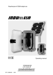
Industrial Weatherproof Telephone
FernTel 3000
UL Registration Number E209659
FCC Registration Number
6SH Ger-35065-TF-E
Ringer Equivalence Number REN 0,9B
User manual
FHF BA 9600-1
12/03
Telephone Characters
LC Display
The telephone is in
programming mode.
Dialling procedure PD
(Pulse Dialling) is ON
The number from the last number
redial memory is being dialled.
Inquiry call mode is ON
Dialling procedure DTMF
(Dual-tone multifrequency) is ON
The Amplified Listening in
Receiver feature is ON
Keyboard
➝
Amplified Listening in Receiver feature
➝
Programming key
➝
Last number redial
➝
Inquiry key
➝
Hash sign (only in DTMF mode)
➝
Asterisk (only in DTMF mode)
Note
Please read the User Manual carefully prior to installing the telephone.
Make sure no equipment parts are missing.
Table of contents
Mounting options
Display and keyboard
Important Safety Instructions . . . . . . . . . . . . . . . . . . . . . . . . . . . . . . . . . . . . . . . 4
Safety and warning notes . . . . . . . . . . . . . . . . . . . . . . . . . . . . . . . . . . . . . . . . . . 4
Package contents . . . . . . . . . . . . . . . . . . . . . . . . . . . . . . . . . . . . . . . . . . . . . . . . 5
General operating instructions . . . . . . . . . . . . . . . . . . . . . . . . . . . . . . . . . . . . . 5
Setting up the telephone . . . . . . . . . . . . . . . . . . . . . . . . . . . . . . . . . . . . . . . . . . 6
Mounting the telephone on the wall . . . . . . . . . . . . . . . . . . . . . . . . . . . . . . . . . . . . 6
Setting up the telephone on the desktop . . . . . . . . . . . . . . . . . . . . . . . . . . . . . . . . 6
Connecting a secondary sounder . . . . . . . . . . . . . . . . . . . . . . . . . . . . . . . . . . . . . . 6
Exchange of a cable gland . . . . . . . . . . . . . . . . . . . . . . . . . . . . . . . . . . . . . . . . . . . 6
Operating procedures . . . . . . . . . . . . . . . . . . . . . . . . . . . . . . . . . . . . . . . . . . . . 7
Setting the ringing melody . . . . . . . . . . . . . . . . . . . . . . . . . . . . . . . . . . . . . . . . . . . 7
Setting the ringing volume . . . . . . . . . . . . . . . . . . . . . . . . . . . . . . . . . . . . . . . . . . . 7
Amplified Listening in Receiver feature . . . . . . . . . . . . . . . . . . . . . . . . . . . . . . . . . . 7
Last number redial . . . . . . . . . . . . . . . . . . . . . . . . . . . . . . . . . . . . . . . . . . . . . . . . . 7
Using the telephone with telephone systems . . . . . . . . . . . . . . . . . . . . . . . . . 7
Network access . . . . . . . . . . . . . . . . . . . . . . . . . . . . . . . . . . . . . . . . . . . . . . . . . . . 7
Programming the automatic pause for network access . . . . . . . . . . . . . . . . . . . . . 7
Disable / enable device programming . . . . . . . . . . . . . . . . . . . . . . . . . . . . . . . . . . 7
Entering and change a Personal Identification Number (PIN) . . . . . . . . . . . . . . . . . 7
Factory settings
.................................................8
Setup procedure . . . . . . . . . . . . . . . . . . . . . . . . . . . . . . . . . . . . . . . . . . . . . . . . . 8
Signal tones . . . . . . . . . . . . . . . . . . . . . . . . . . . . . . . . . . . . . . . . . . . . . . . . . . . . . 8
General notes . . . . . . . . . . . . . . . . . . . . . . . . . . . . . . . . . . . . . . . . . . . . . . . . . . . 9
User Instructions . . . . . . . . . . . . . . . . . . . . . . . . . . . . . . . . . . . . . . . . . . . . . . . . . . 9
Service . . . . . . . . . . . . . . . . . . . . . . . . . . . . . . . . . . . . . . . . . . . . . . . . . . . . . . . . . . 9
Maintenance and cleaning . . . . . . . . . . . . . . . . . . . . . . . . . . . . . . . . . . . . . . . . . . . 9
Replacement parts . . . . . . . . . . . . . . . . . . . . . . . . . . . . . . . . . . . . . . . . . . . . . . . . . 9
Warranty . . . . . . . . . . . . . . . . . . . . . . . . . . . . . . . . . . . . . . . . . . . . . . . . . . . . . . . . 10
Technical data . . . . . . . . . . . . . . . . . . . . . . . . . . . . . . . . . . . . . . . . . . . . . . . . . . . 11
Illustrated operating procedures
3
Warning and security notes
When installing any telephone equipment, please observe to the following guidelines
to ensure the safety of all personnel:
– NEVER install telephone wiring during a lightning storm.
– NEVER install telephone jacks in wet locations unless the jack is specifically designed
for wet locations.
– NEVER touch uninsulated telephone wires or terminals unless the telephone line
has been disconnected at the network interface.
– USE CAUTION when installing or modifying telephone lines.
– TO REDUCE the risk of fire use only No. 26 AWG or larger telecommunication
line cord
This device is a weatherproof telephone designed for use in a rough industry environment.
The following warning and safety notes must be observed:
1. The telephone may be connected to and operated with the prescribed voltage only.
Make sure the telephone is properly connected. The connecting wire must be routed
in a way to prevent persons from tripping over it.
2. The telephone may be operated under the environmental conditions laid down in
Technical Data only. Operation in hostile environmental conditions, for instance too
high or too low ambient temperatures, is not allowed, as this may cause electronic
parts to malfunction.
3. Make sure the telephone connecting wire and any other parts of the telephone are
not damaged. lf the telephone has been damaged it should not be operated.
4. During operation of the telephone legal and professional regulations, safety regulations,
and electrical regulations must be observed.
5. lf the telephone has to be repaired, the repair must be done professionally, using
original spare parts only. Spare parts from other sources may cause damage.
6. Prior to maintenance or replacement of the telephone the line must be disconnected. Maintenance or repair works that have to be carried out while electrical power
is connected may be carried out only by trained and skilled personnel.
7. The listening quality may be marginally reduced due to the influence of strong
external magnetic fields.
8. The manufacturer of this product reserves the right to technical alterations without
further notice.
9. Although this equipment can use either loop disconnect or DTMF signaling,
only the performance of the DTMF signaling is subject to regulatory requirements for
correct operation. It is strongly recommended that the equipment be set to use
DTMF signaling for access to public or private emergency services. DTMF signaling
also provides faster call set up.
4
Package contents
The delivery consists of:
– 1 industrial telephone, type WTS 100
– options bag with latching hook cover and 4 rubber stand-offs (for desktop version)
– this user manual
General operating instructions
1. The weatherproof telephone, type WTS 100, has been developed to access analogue
dial-up ports.
2. The telephone is equipped with a proximity detecting hook switch. This means that
the handset must be put down to interrupt or end an active call.
3. Memory procedures, which begin with the programming key
with this key in order to be stored in memory.
, must also end
4. The receiver must be lifted to enable programming of the different functions.
5. If more than 2 minutes pass without a number being dialed, the exchange may
turn off the power supply. You will then no longer hear a dial tone. In this case
put down the receiver and wait approximately 2 seconds before you lift it again.
Procedures, which you have begun, but not yet completed using the programming
key
, must be repeated.
6. If a procedure has been successfully completed, you will hear an acknowledgement
tone. An error tone informs you in case of an operating error.
7. If you are receiving a call, your telephone will ring with the ringing sound pressure level
you have set. When the telephone is ringing the H E L L O is shown on the display.
8. The receiver has a receiver inset, which is equipped with a magnetic field sender.
User of hearing aids with an inductive receiver may receive the signal of the receiver
inset directly with this telephone.
9. Forgetting the PIN is comparable to losing a key. If you have forgotten your PIN,
please contact one of our service dealers.
5
Setting up the telephone
Mounting the telephone on the wall
Open the telephone by loosing the 4 cover screws 12, and screw the base 1 onto
the wall or another carrier using 3 screws (see front cover for details). Use three 1⁄4-20
machine screws 5 with nuts or #14 wood screws with dowel of appropriate length,
depending on the mounting surface. The mounting surface should be even to rest
on all three stand-offs. Connect the telephone according
to the connection diagram (Fig. 2). Please note that the cable
diameter must comply with the corresponding dimensions of
the cable gland, otherwise the requirements of the NEMA / IP
rating will not be fulfilled. When all the connections have been
made, fasten lid 2 on base 1 with screws 12. The operating
procedures may now be used to perform individual adjustments
Fig. 2
of the telephone. Check for proper telephone operation by
calling to and from another telephone.
Setting up the telephone on desktop
Open the telephone by loosening the 4 lid screws 12, turn lid 2 180° and screw it on
to base 1. It is recommended to remove the latching hook 6 by unscrewing screw 7
and replace it by the enclosed cover. The ship-with, self adhesive rubber stand-offs 8
should be placed in the corresponding recesses in the base. Connect the telephone
according to the diagram (Fig. 2). Check for proper telephone operation by calling to
and from another telephone.
Connecting a secondary sounder
If you want the telephone to control a secondary sounder as well, you will have to replace
the blind plug 10 by a cable gland NPT 1/2" with hexagon 24 mm, NEMA 4X / IP 66.
Please note that the cable diameter must comply with the corresponding dimensions of
the cable gland, otherwise the requirements of the NEMA / IP rating will not be fulfilled.
The secondary sounder is connected at the terminals Second Ringer (Fig. 2). When all
the connections have been made, fasten lid 2 on base 1 with screw 12.
Exchange of a cable gland
If you wish to replace the cable gland fitted in the factory with a different one – use only
size 1/2", NEMA 4X – isolate the telephone from the telephone network. Unscrew the
4 lid screws 12 and open the telephone. Remove the cables from the relevant cable
gland. Loosen the counter nut (spanner size 24) on the cable gland and remove it. Before
fitting a new cable gland, check the seal of the housing for possible damage. Insert a
new cable gland and fasten it with a suitable counter nut. Then pull your cables through
the cable gland and connect each lead as shown in Fig. 2. Follow the instructions given
by the manufacturer of the cable gland regarding type and size of the cable allowed.
When all the connections have been made, fasten lid 2 on base 1 with screw 12.
6
Operating procedures
Using the accompanying procedure and the keys
0 through 9 the ringing melody may be individually
modified. In the factory settings the key 1 is the
active setting.
Using the accompanying procedure the ringing
volume may be adjusted in stages from 1 to 5
(1 = low; 5 = high) and stored, even during
an active call. In the as-delivered condition this
function is set to stage 5.
The telephone enables you to boost the normal
volume in the handset by 6 dB or 12 dB.
After having lifted the handset by used to adjust
the set receiver volume.
When the handset is hung up again, the receiver
volume will return to normal.
If you have dialed a telephone number and the
other participant does not answer, or the line is
busy, please try again by using the last number
redial.
You may program the Inquiry key function
yourself, if you use dual-tone multifrequency
(DTMF)
Programmable Automatic Pause Function
(APF). If a code is required to gain access to the
next level of the network (internal or external) it
is not necessary to pause between the access
code (typically 0 or 9) and the required number.
The APF once activated during set up will
automatically inset the correct delay required by
the system.
The APF offers a choice of short or long
pause to ensure compatibility with most switches. The factory setting is for a short pause.
Please refer to your terminal equipment
documentation to determine the delay
required for your system.
Certain settings, like for instance disable/enable
device programming, are protected by a code
number against random change or misuse.
In the factory setting the PIN 0000 is the active
setting. You may charge the PIN.
• Forgetting the PIN is comparable to
losing a key. If you have forgotten your PIN,
please contact your FHF dealer.
Please unfold back cover !
Setting the ringing options
Setting the ringing sound
pressure level
Amplified Listening
Receiver function
Last number redial
Programming the
enquiry key – earth
Programming the
enquiry key – flash
Entering the APF
Programming the
duration of the APF
Deleting the APF
Disable device programming
Enable device programming
Change PIN
7
Factory settings
The factory settings are as follows:
Dialing procedure
DTMF (tone duration 90 ms)
Amplified Listening in Receiver function
two-stage (6 dB/12 dB)
Signaling Flash
80 ms
Sounder response frequency
(15 … 68) Hz
Automatic Pause Function
3s
Melody
1
Ringing sound pressure level
5
PIN
0000
If the factory setting does not correspond to the technical data of the telephone system
the setup procedure needs to be programmed accordingly.
Setup procedure
Setup performance features
(CODE)
Function
Ringing response
Sounder response frequency
23 … 68 Hz
15 … 54 Hz
23 … 54 Hz
15 … 68 Hz
Dialing parameter
DTMF, tone duration unlimited
DTMF, tone duration 70 ms
DTMF, tone duration 90 ms
PD 1,5 : 1
PD 2 : 1
Deleting memory and restoring the factory settings
Code
41
42
43
44
91
92
93
94
95
33
• When „Restoring the factory settings“ the existing PIN will not be changed automatically.
Signal tones
In addition to the ringing melody, which sounds upon every incoming call, your telephone
may send out further acoustic signals in the form of simple tones, which may serve to
give you useful information during programming.
Tone
Number
Acknowledgement tone 1 long tone
Error tone
8
Significance
Completing a correctly performed procedure
4 short tones An error has been registered during the course
of a procedure. Procedure cancelled.
General notes
User Instructions
Federal Communication Commission regulations require that the following instructions
be followed when connecting to the US public telephone network.
This equipment complies with Part 68 of the FCC Rules. On the front panel of this
equipment is a label that contains, among other information, the FCC Registration
Number and Ringer Equivalence Number (REN) for this equipment. If requested, this
information must be given to the telephone company.
The REN is used to determine the quality of devices you may connect to your telephone
line and still have all of those devices ring when your telephone number is called. In
most, but not all areas, the sum of the REN of all devices connected to one line should
not exceed five (5.0). To be certain of the number of devices you may connect to the
line, as determined by the REN, you should contact your local telephone company to
determine the maximum REN for your calling area.
If your telephone equipment causes harm to the telephone network, the telephone
company may discontinue your service temporarily ( see the note at the end of
this section). If possible, they will notify and you will be informed of your right to file
a complaint with the FCC.
Your telephone company may make changes in their facilities, equipment, operations,
or procedures that could affect the proper functioning of your equipment. If they do,
you will be notified in advance to give you an opportunity to maintain uninterrupted
telephone service.
Note. The telephone company may ask that you disconnect this equipment from the
network until the problem has been corrected or until you are sure that the equipment
is not malfunctioning.
This equipment may not be used on party lines or coin service provided by telephone
company.
Service
You have purchased a modern FHF product, which has been subject to rigid quality
control. lf you have any questions about this telephone, or if malfunctions should occur
even after the guarantee period – please contact your FHF dealer. Before you make
the call, however, please find the type and product numbers on the product name plate.
Maintenance and cleaning
The telephone is maintenance free. lf it is operated in areas where it is subjected
to large amounts of dust, grease, oil etc. the telephone should be cleaned from time
to time. Use a moist cloth to wipe off the device. Warning ! Never use sharp
or pointed instruments to clean the telephone. Do not use cleaning agents.
Replacement parts
For a detailed list please contact your local agent or contact email: [email protected]
9
Warranty
Equipment. FHF warrants for a period of one (1) year from the data of shipment,
that any FHF equipment supplied hereunder shall be free of defects in material and
workmanship, shall comply with the then-current product specifications and product
literature, and if applicable, shall be fit for the purpose specified in the agreed upon
quotation or proposal document. If (a) Seller’s goods prove to be defective in workmanship and/or material under normal and proper usage, or unfit for the purpose
specified and agreed upon, and (b) Buyer’s claim is made within the warranty period
set forth above, Buyer’s sole and exclusive remedy, and the warranty period on any
repaired or replacement equipment shall be one (1) year from the date the original
equipment was shipped. In no event shall FHF warranty obligations with respect to
equipment exceed 100 % of the total cost of the equipment supplied hereunder.
Buyer may also be entitled to the manufacturer’s warranty on any third-party goods
supplied by FHF hereunder. The applicability of any such third-party warranty will
be determined by FHF.
Services. Any services FHF provides hereunder, whether directly or through subcontractors, shall be performed in accordance with the standard of care with which such
services are normally provided in the industry. If the services fail to meet the applicable
industry standard, FHF will, for a period of one (1) year from the date of completion,
re-perform such services at no cost to Buyer. Re-performance of services shall be
Buyer’s sole and exclusive remedy, and in no event shall FHF warranty obligations with
respect to services exceed 100 % of the total cost of services provided hereunder.
Warranty Periods. Every claim by Buyer alleging a defect in the goods and/or services
provided hereunder shall be deemed waived unless such claim is made in writing within
the applicable warranty periods as set forth above. Provided, however, that if the defect
complained of is latent and not discoverable within the above warranty periods, every
claim arising on account of such latent defect shall be deemed waived unless it is made in
writing within a reasonable time after such latent defect is or should have been discovered
by Buyer.
Limitation / Exclusions. The warranties herein shall not apply to, and FHF shall not be
responsible for, any damage to the goods or failure of the services supplied hereunder,
to the extent caused by Buyer’s neglect, failure to follow operational and maintenance
procedures provided with the equipment, or the use of technicians not specifically
authorized by FHF to maintain or service the equipment.
THE WARRANTIES AND REMEDIES CONTAINEND HEREIN ARE IN LIEU OF AND
EXCLUDE ALL OTHER WARRANTIES AND REMEDIES, WHETHER EXPRESS OR
IMPLIED BY OPERATION OF LAW OR OTHERWISE, INCLUDING ANY WARRANTIES
OF MARCHANTABILITY OR FITNESS FOR A PARTICULAR PURPOSE.
10
Technical data
FCC Registration Number
UL Registration Number
Ringer Equivalency Number
Connecting data
Line voltage
Line current
Ringing alternating current
Ringing frequency
Input impedance
Earth function
Pulse dialing (PD)
Dialing frequency
Pulse/pause ratio
Dual-tone multifrequency (DTMF)
CCITT Q23
Ringing sound pressure level approx.
Housing
Material
Height x Width x Depth approx.
Weight approx.
Display
Operating position
Handset (receiver)
Microphone
Receiver inset
Connections
Network connection (USOC)
Secondary sounder Second Ringer
Signaling at private branch exchanges
Ringing loudspeaker
Environmental conditions
Ambient operation temperatures
Transport and storage temperatures
Humidity
Degree of protection
6SH GER-35065-TF-E
E209659
REN 0,9B
24 ... 66 VDC
18 ... 100 mA
30 ... 150 VAC
16,67 ... 54 Hz
≥ 6,0 Ω bei 25 Hz
≥ 3,5 Ω bei 50 Hz
Line Tip to Signal Earth available
10 Hz
2,0 : 1 66,7 / 33,3 ms
1,5 : 1 60,0 / 40,0 ms
-6 dB power level of the low group
-4 dB power level of the high group
96 dB (A) at 1 m / 3,3 ft
Polycarbonat UL 94V-5A
380 x 240 x 148 mm/10,63 x 7,87 x 5,43 in
3,6 kg / 8,1 lbs
16 digits, digit height 11mm, pictograms
Desktop or vertical wall mounting
Electret condenser
Dynamic receiver inset, meets hearing aid
compatibility technical standards per
FCC Section 68.316
Connectors up to 2,5 mm2 / AWG 14
Tip / Ring
Signal Earth
permanently connected
-10° to +50° C / +14° to 122° F
-20° to +60° C / -4° to 140° F
90 % non-condensing
IP 66 (IEC 529)/ Type 4X Enclosure (UL 50)
11
Operating Procedures
(0…9)
(1…5)
(+0 dB)
(+6 dB)
(+12 dB)
(+0 dB)
(001…999 ms)
(max. 15)
(max. 15)
(1 s…8 s)
(PIN)
(PIN)
(old PIN)
(new PIN)
(new PIN)
Al rights reserved. Subject to availability.
Right of modification reserved.
FHF Funke + Huster Fernsig GmbH
P. O. Box 10 03 05 · D-42503 Velbert · Germany
Telephone +49 / 20 51 / 270-0 · Telefax +49 / 20 51 / 270-377
http://www.fhf.de · e-mail: [email protected]