1
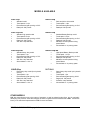
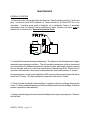
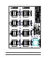
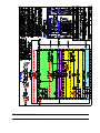
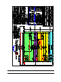
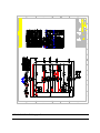
OPERATION AND MAINTENANCE MANUAL
NXL SERIES
HYDRAULIC SLIDING GATE OPERATORS
Revised 11/03
Model:_____________
Serial #:____________
For service or maintenance, contact:
CONTENTS
SECTION ONE: GENERAL INFORMATION
GENERAL DESCRIPTION........................................................................................................ 1
FEATURES ............................................................................................................................ 2
MODELS AVAILABLE ............................................................................................................. 3
SECTION TWO: INSTRUCTIONS
INSTALLATION ....................................................................................................................... 1
MAINTENANCE .................................................................................................................... 12
TROUBLE SHOOTING........................................................................................................... 15
SYMPTOM GUIDE .................................................................................................... 15
CONTROL COMPONENT LOGIC................................................................................ 21
CONTROL COMPONENTS KEY................................................................................. 24
FUNCTIONAL SCHEMATIC........................................................................................ 25
TROUBLE SHOOTING WORKSHEET......................................................................... 26
TECHNICAL ASSISTANCE ........................................................................................ 32
SECTION THREE: INSTALLATION INFORMATION (DRAWINGS)
ISOMETRIC OF TYPICAL INSTALLATION (0050AI0013) ............................................................ 1
XL, XLH, XLB, XLF, XLS, XLSB, XLSF, AND XLR INSTALLATION (0050AI0002)............................. 2
XLT GENERAL INSTALLATION (0050AI0115)............................................................................ 3
XLD TYPICAL INSTALLATION (0050AI0114) .............................................................................. 4
STANDARD DRIVE RAIL INSTALLATION (0050AI0208) .............................................................. 5
DRIVE RAIL INSTALLATION (0050AI0177)................................................................................. 6
XL PROXIMITY SWITCH INSTALLATION AND ADJUSTMENT (0050BA0201)................................ 7
XL PROXIMITY SWITCH AND EXTENDED TRIP PLATE (0050BA0203) ........................................ 8
SECTION FOUR: WIRING INFORMATION (DRAWINGS)
WIRING SPECIFICATIONS (0050BL0053) ................................................................................. 1
VOLTAGE CONVERSION, SINGLE PHASE (0050BE0009) ........................................................ 2
VOLTAGE CONVERSION, THREE PHASE (0050BE0010) ......................................................... 3
CONTROL TRANSFORMER WIRING (0050AE0069) .................................................................. 4
ELECTRICAL DIAGRAM, STD SINGLE PHASE (EXCEPT TYPES B AND F) (0050BE0204) .......... 5
ELECTRICAL DIAGRAM, STD THREE-PHASE (0050BE0205) .................................................... 6
XLR SERIES OPERATOR WIRING SCHEMATIC (0050DE0741).................................................. 7
ELECTRICAL DIAGRAM, FAIL SAFE (XLF AND XLS) (0050BE0207) ........................................... 8
ELECTRICAL DIAGRAM, BATTERY BACKUP (XLB AND XLSB) (0050BE0206)............................ 9
TYPICAL ACCESSORIES AND OPTIONS WIRING (0050BE0212)............................................. 10
MASTER-SLAVE OPTION WIRING (0050BE0049) ................................................................... 11
XL INTERLOCK PACKAGE (0050BE0141)............................................................................... 12
INTERMEDIATE LIMIT SWITCH ADAPTION WIRING (0050AE0149) .......................................... 13
SECTION FIVE: LAYOUT AND PARTS IDENTIFICATION (DRAWINGS)
STANDARD HYDRAULIC CIRCUIT (0050AH0011) ...................................................................... 1
XLT HYDRAULIC CIRCUIT (0050AH0112) .................................................................................. 2
XLR HYDRAULIC PLUMBING (0050DA0740) ............................................................................. 3
XLD HYDRAULIC CIRCUIT (0050AH0123).................................................................................. 4
FAIL SAFE (TYPE F) AUXILLIARY ELECTRICAL ENCLOSURE LAYOUT (0050BE0145)............... 5
BATTERY BACKUP (TYPE B) MAIN ENCLOSURE LAYOUT (0050BE0135) ................................ 6
BATTERY BACKUP (TYPE B) AUXILLIARY ENCLOSURE LAYOUT (0050BE0134) ...................... 7
STANDARD 1_ CONTROL CUBICAL LAYOUT (0050BE0019) ..................................................... 8
TYPICAL OPERATOR ASSEMBLY (0050AA0093)..................................................................... 9
SECTION SIX: PARTS LIST
REPLACEMENT PARTS.......................................................................................................... 1
MECHANICAL............................................................................................................. 1
HYDRAULIC ............................................................................................................... 3
ELECTRICAL.............................................................................................................. 4
GENERAL DESCRIPTION
The B&B ARMR Corporation. NXL Series Sliding Gate Operators are designed to reliably
operate any style of sliding gate, including large or heavy gates. Common applications include
automatic operation of commercial and residential entry gates, condominium and subdivision
access control gates, airport security gates, and prison access control gates. The operator is
unobtrusive in appearance yet durable under heavy use in both commercial and residential
installations. The design incorporates many excellent features intended to improve safety and
security, increase reliability, and reduce maintenance.
Controls operate on safe and reliable 24VAC voltage (24VDC on Battery Backup units). A
transformer, completely prewired, is installed in each operator to step down the input voltage.
The operator actuates the gate by rotating two wheels (the NXLR operator uses a pinion gear).
A drive rail bolted to the gate is drawn between the two wheels by friction. The wheels are
spring-loaded against the drive rail to produce a positive friction feed in both directions.
Spring loading of the wheels also serves to correct for wheel wear. The wheels are rotated by
series-connected hydraulic motors to minimize uneven rotation between the wheels.
Rotation direction is determined by the hydraulic valve system, not by the direction of electric
motor rotation. Independence from the electric motor rotation has the advantage that the
direction of gate travel can be instantly reversed without the use of brakes.
GENERAL INFORMATION page 1-2
FEATURES
•
•
•
•
•
•
•
•
•
•
•
•
•
•
•
•
•
•
•
•
•
•
Simple toggle switch right-hand to left-hand conversion (no wiring changes, limit switch
swapping, hose swapping, etc.)
Safe 24VAC controls standard (24VDC on Fail Safe and Battery Backup units)
Low maintenance - no sprockets, chains, brakes, or pulleys to adjust
Direct-position feedback for motion control
May be used with any type of sliding gate (cantilever, overhead track mounted, or
ground track)
Wear-compensating, spring loaded, friction-feed drive.
Prewired relay board, with multiple built-in features and "plug-in" options, eliminates
complex and confusing internal circuit wiring
Wide range of control options including, but not limited to, combinations of:
Remote push-button station(s)
Loop detector
Single button control
Free exit
Obstruction detector
Emergency open
Time delay close
Radio control
Master-slave control
Warning light / buzzer
Complete, easy reference wiring diagrams for all standard control options
Add-on prewired relay boards simplify the addition of more complicated control options
Built-in adjustable maximum run timer
Proximity limit switches, eliminates "false" tripping due to misaligned drive rail
Instant reverse capability during close cycle for safety and obstruction detection
Laminated wiring diagram in the electrical box
Standard units available in 115/208/230 single phase, and 208/230/440 three phase
Built-in low-voltage compensation capability
Rigid, lightweight aluminum drive rail for easy gate mounting
Increased security over chain drive units (no chains to cut or pins to remove)
Drive wheels are automatically locked when unit is de-energized, making the gate pryresistant
Clearly illustrated installation, maintenance, and trouble-shooting instructions
Linkage-type quick-action hand release for manual operation
Limited 5-year factory warranty
GENERAL INFORMATION page 1-3
MODELS AVAILABLE
NXL-15vp
•
•
•
•
Standard model
Travel speed: 1.2 fps
Recommended gate opening: to 50 ft
Rated pull: 300 pounds
NXL-15vp-HS
•
•
•
•
•
Standard high speed model
Travel speed: 2.2 fps
Recommended gate opening: to 50 ft
Rated pull: 300 pounds
Soft start / stop standard
NXLR-15vp
•
•
•
•
NXLB-13vp
•
•
•
•
•
•
NXL-20vp-HD
•
•
•
•
•
•
Standard heavy -duty model
Travel speed: 1 fps
Recommended gate opening: to 75 ft
Rated pull: 400 pounds
Soft start / stop standard
Not available in 110v 1∅
•
•
•
•
•
•
Extra heavy -duty model (four hydraulic
motors)
Travel speed: 1 fps
Recommended gate opening: 150 ft
Rated pull: 500 pounds
Soft start / stop standard
Not available in 110v 1∅
Standard Battery Backup model
Travel speed: 1.2 fps
Recommended gate opening: to 50 ft
Rated pull: 200 pounds
Maintains normal operation during
power failures
Not available in 3∅ primary power
NXLB-13vp-HS
•
•
•
•
•
•
NXLD-20vp
Rack-and-pinion drive model
Travel speed 1.4 fps
Recommended gate opening: to 50 ft
Rated pull: 300 pounds
High Speed Battery Backup model
Travel speed: 2.2 fps
Recommended gate opening: to 50 ft
Rated pull: 200 pounds
Maintains normal operation during
power failures
Not available in 3∅ primary power
XLT-30v3
•
•
•
•
•
•
Super heavy -duty model (six hydraulic
motors)
Travel speed: 1 fps
Recommended gate opening: 300 ft
Raged pull: 700 pounds
Soft start / stop standard
Not available in 1∅ primary power
OTHER MODELS
B&B also manufactures many other types of operators, as well as related product lines, and is continually
developing new products. More than 50 types of aluminum gates are also manufactured at B&B. Contact the
factory or an authorized representative of B&B for more information.
GENERAL INFORMATION page 1-4
INSTALLATION
Before you begin: Read all installation information before beginning work. Study all pertinent
drawings. Be certain to refer to the correct wiring diagrams for your operator model.
Knowledge of standard construction p rocedures is assumed. Electrical work should be done
by qualified electrical technicians.
1. Identify your operator model. Write the model number and serial number on the lower left
hand of the cover sheet of this handbook in the spaces provided for easy future reference.
The information is on a stamped tag attached to the outside of the operator housing. be sure
to include the complete model number, which identifies operator configuration, horse power,
supply voltage required, and motor phase. The model number is XL_____-_____-_____. If
multiple operators are installed at this location, record information which will permit
identification of each operator's model and serial number.
2. Refer to the installation drawing, page 3-2 for most operators, for complete structural
installation details. If your gate is an XLT refer to page 3 -3, or an XLD refer to page 3 -4. Note
the left hand / right hand orientation of the gate.
3. Install the gate. Installation of the gate depends on the gate and mounting design. Obtain
assistance from the gate manufacturer if required. It is critical that the gate move freely and
easily over its full travel without binding. Gates which cannot be easily opened will place undue
stress on the operator, reducing the life of the operator and the gate especially in high-speed
operator installations. Operators are designed to provide convenience and safety, not to force
a gate open or closed.
INSTRUCTIONS page 2-1
GENERAL INFORMATION page 1-2
NOTE: Gates requiring more than 25% of the operator's rated draw force may experience
slipping in wet conditions.
IMPORTANT: A requirement for NXLR installations and a recommendation for other models
is that the gate must be guided within 3 feet of the operator by guides which permit no more
than 1/4 inch movement in or out from the operator. This can be accomplished with bottom
guides or cantilever rollers. It is important that this be done before installing the operator.
4. Splice the drive rail. The drive rail length is the gate opening plus at least 4 feet. Add at
least 6 feet for the NXLT operator. If you have chosen to locate the operator further back from
the opening than the minimum shown on the installation drawing, be sure to lengthen the drive
rail by the additional setback. If more than 24 feet of drive rail is required, or if multiple pieces
of drive rail are used, the drive rail must be spliced using the splice kit provided. The
manufacturer recommends that the drive rail run the entire gate length in order to dissipate
vibration and shock loading. For standard rail, refer to the drive rail drawing on page 3-5. If
installing an NXLR, see page 3-6 and page 3-7.
5. Lay the electrical conduit according to the site plans and appropriate codes. Note the
location of the conduit entrance in the operator housing for the best stub-up location. Power
and control wiring are to be run in separate conduits.
6. Pour a concrete pad for the operator. Minimum dimensions are provided on the
appropriate installation drawing (see section 3). Allow 24 hours for the concrete to cure before
using the gate operator. Note: In unusual circumstances where the gate travels on a sloped
path, the pad surface should slope with the gate path as closely as possible for best operation.
7. Locate the operator on the pad. The operator frame must be adjusted so that the
drive wheels are parallel to the gate, with the center of the drive wheels 3 inches from the
closest face surface of the gate. A quick and accurate method for accomplishing this is to
attach clips to each end of the gate with a string tied between them 3" out from the face of the
gate. Use the operator as a template for locating the anchor bolts. See the appropriate
installation drawing for anchor bolt requirements.
NOTE: Bowed or warped gates must be straightened or replaced. If a straightened bow
remains somewhat warped, place the operator with the drivewheels 3" from the closest point
on the gate. Shim the drive rail as needed where the gate bows away from the operator to
keep the rail straight and parallel to the gate travel.
INSTRUCTIONS page 2-3
8. Release the drive wheels. Remove the housing cover. Pull the quick release handle back
to release tension on the drive wheels.
Caution: The quick release design holds the wheels apart, but it is not locked in this position.
Bumping the mechanism or jarring the operator can cause the mechanism to snap back to the
clamped position. Always keep fingers etc. clear of the mechanism path to avoid injury.
9. Mount the drive rail on the gate. Mounting will vary depending upon the gate style. The
manufacturer recommends using hex head bolts to attach the drive rail to the gate. Drill
through the gate's vertical post and the 3" vertical side of the drive rail. Bolt the rail to the
vertical post. The 4" horizontal part of the drive rail should pass between the wheels,
maintaining the correct height at the wheels over the full travel of the gate.
NOTE: This might not be level or parallel with the bottom of the gate because of an uneven or
irregular roadway or gate track. The horizontal portion of the drive rail should be parallel with
the surface of the mounting pad to prevent undue stress (refer to the above illustration). Shim
as needed to keep the rail straight (refer to step 7). For the XLR, see page 3-7.
INSTRUCTIONS page 2-4
10. Install the vent cap in the pump unit. Remove the red shipping plug and replace it with the
vent cap, which is shipped attached to one of the hydraulic hoses with a wire tie. Failure to do
so will damage the operator, and will void the manufacturer's warranty.
11. Move the proximity limit switch out 3/4 of an inch. The proximity limit switch has a metal
sensitive area approximately 3/4 of an inch long. Unscrew the limit switch from its shipping
position flush with the casing. See drawing 0050BA0203 page 3 -9 for high speed or rack and
pinion operators, and 0050BA0201 page 3-8 for standard speed operators.
INSTRUCTIONS page 2-5
IMPORTANT: Steps 12 through 18 should be completed by a qualified electrical
technician.
12. For left hand gate installations, change both toggle switches inside the control enclosure
to the left hand position marked on the prewired relay board. No wiring changes, limit switch
swapping, or hose swapping is required. Refer to the illustration below.
13. Install a jumper wire between terminals 2 and 4 if a three button push-button or other "stop"
contact is not to be used. The jumper must be installed or the gate will not operate. Install the
jumper when the push-button is disconnected. See illustration above.
14. Run and connect all power and control wiring according to national and local codes.
Power and control wiring must be run in separate conduits.
Refer to the wiring specifications chart 0050BL0053 on page 4-1 to choose the correct wire
gage. the wiring charts take both the motor's full load amperage into consideration and the
amperage needed to power peripheral equipment required for a complete gate system.
Locate the correct wiring diagram for your gate model and supply power in section 4 of this
handbook and mark it clearly. The correct wiring diagram for your gate is also located inside
the lid of the control enclosure.
INSTRUCTIONS page 2-6
Proper grounding of the unit is required. This is accomplished by connecting a ground wire
between the ground terminal inside the disconnect switch housing and a copper ground rod
located as close to the operator as possible. It is important that an earth ground be used, and
not an electrical ground.
15. If the gate must be converted to an alternate supply voltage, refer to the voltage conversion
drawings for single phase operators (0050AE0009 and 0050AE0069, p. 4 -2 and 4-4) or for
three phase operators (0050AE0010 and 0050AE0069, p. 4-3 and 4-4), as appropriate.
NOTE: Battery Backup and Fail Safe operators are not set up for field conversion of primary
power.
Make necessary wiring changes at the control transformer and electric motor. Electric motor
wiring for the various voltages is usually stamped on the motor, and should always be checked.
The motor is to be run counterclockwise in all operators. The wiring is subject to change by
the motor manufacturer, and changes may not be reflected in this handbook.
NOTE: Most NXL series operators use motors with built-in overloads. If your operator has
overloads located in the electrical enclosure, contact technical support for rewiring assistance.
NOTE: If the supply voltage is low, it is recommended that the low voltage taps (104V, 208V,
or 416V) provided on the control transformer be used.
16. Test run the operator. Make sure the drive wheels are disengaged before connecting the
power.
NOTE: If three phase power is used and the motor runs but the drive wheels do not turn,
reverse two poles (swap two wires) of the three phase power source. If the operator cuts off
unexpectedly, refer to step 20.
Test the "open" function by momentarily jumping terminals 1 and 4, or pressing the open
button. The wheels should turn counter-clockwise. Stop the gate by pressing the stop button,
manually activating the open limit switch (using a small metal plate) or disconnecting the
power.
Test the "close" function by momentarily jumping terminals 4 and 3, or pressing the close
button. Stop the gate by either pressing the stop button, manually activating the close limit
switch (using a small metal plate), or disconnecting the power.
INSTRUCTIONS page 2-7
Test the instant reverse feature by first momentarily jumping terminals 4 and 3 (giving a "close"
signal), then momentarily jumping terminals 1 and 4 (giving an open signal). For safety
reasons, the circuit is designed to prevent the instant reverse feature from working while the
gate is opening. During the open cycle, the gate must be stopped, and then reversed.
17. Connect and test accessory controls. Refer to the accessory wiring diagram on page 4-9,
or to the master-slave wiring diagram on page 4-10.
18. Check limit switch alignment. Manually push the gate to its fully open and fully closed
position and verify that the proximity limit switches are 1/4" from the trip plate surface. Adjust
the limit switches until this distance is reached.
IMPORTANT: The minimum distance between the limit switch and the housing is 3/4". Less
distance will cause the limit switch to give a false indication.
19. Engage the drive wheels. Engage the
drive wheels by carefully pushing the quickrelease handle back to the original position,
keeping fingers clear of pinch points.
Repeat the gate function tests (steps 16
and 17). Be sure the gate does not bind
and the drive rail remains aligned between
the drive wheels during full travel. If the
wheels slip, tighten down on the spring
adjustment nut until no slippage occurs
during normal gate travel. Momentary
slippage when starting, stopping, or
reversing is acceptable. Tighten the spring
only enough to eliminate slippage during
normal travel. Over-tightening will shorten
the wheel life. Refer to illustration.
Special note for NXLR installations: To adjust the spring setting, release the drive mechanism
(wheel and pinion) with the quick release. Place the rail / rack between the wheel and pinion,
aligning the gear teeth. Return the quick release mechanism to the "engaged" position, sliding
the gate a bit if necessary to obtain a good mesh between the rack and pinion. If the teeth fully
engage, loosen the spring until a slight gap is seen. Tighten the spring adjustment nut just until
the teeth are fully meshed, then tighten the
INSTRUCTIONS page 2-8
spring an additional 2 to 3 full turns. Do not over tighten. The spring holds the rack and
pinion engaged, overtightening does not increase the pull capacity, and will result is excessive
wear and grinding of the teeth.
20. Set the maximum run timer. Measure the time required to run the gate through a complete
cycle (open and closed) and set the maximum run timer to slightly longer than this time. The
maximum run timer is the time delay labeled TD1 on the pre-wired relay board inside the
electrical enclosure. Each number on the timer represents 10 seconds.
For example, if a complete cycle requires 35 seconds, 1 8 seconds to open and 17 seconds to
close, the knob pointer on TD1 should be set on 4, for 40 seconds maximum run time. Refer
to the illustration.
NOTE: If the maximum run timer times out, the power to the operator must be turned off and
back on to reset the timer. This prevents the operator from attempting to run every time it
receives an "open" or "close" signal when the gate is stuck or jammed. An alternate, multiplerange maximum run timer (TD1), similar in appearance to that shown, may be provided on
NXLD and NXLT models to permit maximum run times greater than 100 seconds for unusually
long gate openings.
21. If the drive rail is fastened to the gate with U-bolts or by another method which could allow
the rail to move (if the gate were jarred for example), the use of a positive fastening device is
recommended. Small holes should be drilled through the drive rail into the vertical members of
the gate, and self-tapping screws used to lock the rail into position.
INSTRUCTIONS page 2-9
22. Warning signs should be mounted in a visible location per applicable safety codes
instructing traffic to maintain a safe distance clear of the gate path.
23. Installation of positive gate stops is recommended. They should be 1 or 2 inches past the
normal travel of the gate.
24. Record the names and phone numbers of the dealer, installer, and other important
contacts, in this handbook.
25. Leave the handbook, along with any supplements, with the owner. Have them keep these
materials in a place where they will be readily available for future maintenance, control
modifications, trouble shooting, etc. If additional handbooks are needed, contact your dealer
or an authorized B&B ARMR distributor.
INSTRUCTIONS page 2-10
ADDITIONAL SAFETY ADVICE FOR AUTOMATIC OPERATOR
INSTALLATION
1. A safety loop, or some other presence-detecting safety device, is advised for all automatic
gate operator installations. One should always be used with high-speed operators. Safety
devices which reverse the gate on contact with an o bstruction (gate mounted safety edges, for
example) are not recommended as primary safety controls.
2. Two safety loops, one on each side of the gate, are advised when a timed gate closure is
installed (TD-2). This will ensure that the vehicle completely clears the gate before it begins to
close.
3. High speed operators (2 fps or more) are not recommended for pedestrian access
installations.
INSTRUCTIONS page 2-11
4. For safety and for best operator service, the gate design should consider the large kinetic
energy (potential impact force) associated with high-speed operation. Kinetic energy is
directly proportional to the velocity squared. For example, a gate traveling 5 feet per second
has 25 times the momentum it would have traveling at 1 foot per second. Thus, the lowest
operational speed practical should be chosen for each gate installation.
5. To reduce kinetic energy at the chosen operating speed, the gate should be as lightweight
as possible. Gates made from aluminum are preferable to those made from steel.
INSTRUCTIONS page 2-12
MAINTENANCE
HYDRAULIC SYSTEM
1. Remove the vent / fill plug and check the fluid level. Keep the fluid level within 1" of the vent
plug. Use Exxon Univis #J-26 hydraulic oil, Texaco aircraft oil 15, Mobile DTE 24, or an
equivalent. If another good grade of hydraulic oil is substituted, Dextron II automatic
transmission fluid, for example, can be substituted in warm climates; the old oil must be
drained first to avoid mixing. Never mix hydraulic fluids.
2. Hydraulic fluid requires infrequent replacement. The frequency of fluid replacement is highly
dependent upon operating conditions. The oil's operating temperature, which is determined
by a combination of outside air temperature, number of cycles, gate length, pressure required
to move the gate, and so on, is the most critical factor in determining oil life. Replace the oil
any time it becomes dark, discolored, contaminated with small trash particles, or opaque.
As a general guide, on high cycle installations (300 or more cycles per day) replace the fluid at
least every 2-3 years. On other installations, replace the fluid every 3-5 years.
3. Check for leaks in hydraulic lines and fittings. Leakage could occur in fittings after a period
of use. If it does, moderate tightening of the hose fittings should stop the leakage. If the leak
persists, replace the hose assembly.
4. Always operate the gate several times after adding fluid to expel any trapped air. Recheck
the fluid level.
INSTRUCTIONS page 2-13
5. Check the condition of the drive wheels. Look for large cracks or pieces of polyurethane
(rubber-like tread) which have broken off. Drive wheels require periodic replacement under
normal service when the polyurethane begins to crack or become out-of-round. Over
tightening the wheel clamping spring will shorten wheel life. See page 2-7 instruction 19 for
information on spring adjustment.
6. The 4-way hydraulic valve could occasionally stick if lint or other debris gets trapped in the
valve spool. Manually shifting the valve spool in both directions several times will usually clear
this problem. This is done by pushing the small pin in each end of the solenoid coil. See the
following illustration.
RACK AND PINION (XLR) OPERATORS ONLY:
1. The teeth of both the rack and pinion gear must be lubricated every few months with either
Texaco Molytex EPZ, or Exxon Ronex Extra Heavy Duty Moly. It should be done more often
under high use or harsh conditions.
INSTRUCTIONS page 2-14
ELECTRICAL CONTROLS:
CAUTION: TURN OFF POWER BEFORE SERVICING
1. No regular maintenance is required on electrical gate controls. Refer to trouble shooting
section if a problem occurs with gate controls.
2. Keep controls clean and dry.
INSTRUCTIONS page 2-15
TROUBLE SHOOTING
SYMPTOM GUIDE
IMPORTANT:
1. Servicing of the gate controls should only be done by experienced electrical
technicians.
Many safety features have been built-in to protect service personnel. However, as
with any electrical equipment, severe injury from electrical shock or damage to
control components can result from improper servicing of the controls.
2. Always disconnect power before servicing any electrical component.
3. All voltages must be checked under load, i.e. with operator running or attempting
to run.
A. The power unit runs, but the wheels do not turn.
1. Check the fluid level. Maintain the fluid to within 1" of the vent cap with Exxon Univis
# J-26 hydraulic oil, Texaco aircraft oil 15, Mobile DTE 24, or equivalent. It is important
to completely drain the old oil. Do not mix oils.
2. Reverse two legs of three-phase power source.
3. If the operator has undergone a field conversion to accept an alternate supply
power, check the motor wiring to be sure it is wired correctly for counterclockwise
rotation.
4. Manually operate the 4-way valve several times by pushing the pins in the center of
the solenoid coils back and forth. See instruction 6, and the illustration on page 2 -13 in
the maintenance section for assistance in identifying the solenoid valve and pins.
5. Check the control circuit voltage between terminals 13 and 4 with the operator
attempting to run. The voltage must be between 24 and 32 volts for reliable operation.
If the measured voltage is close to 24, transient voltage drops could fall significantly
below 24 volts. The motor contactor and the relays will not function reliably when the
INSTRUCTIONS page 2-16
voltage drops too low. If the control voltage is too low or is marginal:
a. check the supply voltage at the source. If the supply voltage is below
110/240/480 VAC, contact the utility company to correct the problem, or use the
alternate low voltage taps on the control transformer (104, 208, or 416 volt taps).
Refer to the transformer wiring diagrams on page 4-4.
b. measure the total distance between the power supply and the operator.
Refer to the wiring specifications chart on page 4-1 to check the wire gage
required to avoid excessive voltage drop. Follow the chart recommendations.
Use the next larger size wire gage if the supply voltage is marginal for the
distance required. If the problem can not be corrected, use the alternate low
voltage taps on the control transformer (104, 208, or 416 volt taps). Refer to the
transformer wiring diagram on page 4-4.
6. If the above steps do not solve the problem, check the hydraulic pressure by
inserting a pressure gauge into the pressure port. The pressure port is located at
roughly 12 o'clock on the pump section of the power unit (the "neck" section). The plug
can be removed with a 5/16" Allen wrench. The port accepts 3/8" male pipe threads.
With the gate attempting to run, measure the pressure and note the pattern of pressure
build up, if any. Record this information and call for technical support (see page 2 -31)
B. The power unit runs and the wheels turn, but the gate does not move.
1. Check the gate for free movement. Remove the housing cover and release the
drive wheels by slipping the quick release handle over the base and rotating the handle
until the linkage snaps into place as per page 2-3. Pull the gate manually through the
full travel in both directions to be sure there is no binding.
2. If the gate slides freely, check the drive wheel spring tension. for normal
applications, with the exception of NXLR installations, the nut should be flush with the
end of the threads, or up to 1/4" of the threads on the spring bolt should extend beyond
the nut. (See note on page 2-7 instruction 19 for the XLR)
3. Check the drive rail for ice, oil, or slick spots. Clean the rail if oil or some other slick
INSTRUCTIONS page 2-17
deposit is causing the problem. If the problem is ice, try tightening the spring pressure
on the drive wheels to crunch through the ice. Aluminum drive rail is recommended for
icy installations, because ice on a slick aluminum surface shatters and falls off more
easily than ice on a textured surface like galvanized steel. The XLR is recommended
where extreme environmental conditions reduce traction to nearly zero for friction drive
mechanisms.
4. If the above steps do not resolve the problem, check the hydraulic pressure by
inserting a pressure gauge into the pressure port. The pressure port is located at
roughly 12 o'clock on the pump section of the power unit (the "neck" section). The plug
can be removed with a 5-16" Allen wrench. The port accepts 3/8" male pipe threads.
With the gate attempting to run and the wheels locked or held back, measure the
pressure and note the pattern of pressure build-up, if any. Record this and call for
technical support (see page 2-31).
C. The gate does not fully open or fully close.
1. Check for gate obstructions or binding.
2. Check the setting of the maximum run timer (TD1). Refer to page 2 -8, instruction 20
for instructions on setting the timer.
NOTE: If the timer has timed out, recycling power (switching the disconnect switch off
and back on) to the operator will reset the timer.
3. Check for a loose drive rail on the gate and correct it if necessary.
4. Note the ambient temperature. Does the operator resume normal operation if the
disconnect switch is switched off and then back on? If the gate is running too slow due
to an extremely low ambient temperature, the maximum run timer could we tripping off
before full travel is completed. To check this, note the setting of the maximum run timer
and time the gate for a full cycle (from closed to open to closed). See the installation
section page 2-8 instruction 20. If this is the problem, limited compensation can be
achieved by increasing the time on the maximum run timer. In cold weather areas
where temperatures go below 0?F, the operator cabinet could be heated with an
optional heater and thermostat.
INSTRUCTIONS page 2-18
NOTE: The maximum run timer can be reset by recycling power to the operator.
D. The gate operator does not cut off immediately when the full opened or closed position is
reached.
1. Check the proximity limit switch and stop plates for correct placement. See the
installation section (page 2-7, instruction 18) for information.
2. Release the drive wheels by removing the cover and operating the quick-release
mechanism. Check for faulty limit switches following the testing procedure given in the
installation section (page 2-5,6 instructions 13 and 16)
E. The power unit does not run.
1. Recycle the power. If the gate then operates properly, the maximum run timer (TD1)
had timed out. Check to see that the timer is set correctly. Refer to the installation
section page 2-8 instruction 20. If the timer is set properly, check the gate for binding
or jamming and correct this condition if it exists.
2. Check the incoming power source. Be sure all three legs of the three phase source
have power. If the voltage is low, contact the utility company to correct the problem.
3. Check the motor overloads. Most motors used on XL operators have built-in
manual reset overloads. The built-in overload is a button on the side of the motor
junction box. If the overloads are the manual reset type and are tripped (popped out),
reset the overloads (push in to reset). Also check to see that the overload condition
was not caused by binding or blockage. If so, correct the condition.
CAUTION: Separate overloads (not built-in to the motor) on three-phase gates open
an auxiliary contact in the control circuit to disable the operator, they do not break the
power circuit. Three phase operators can be forced to run in an overloaded condition if
the contactor is manually held in.
INSTRUCTIONS page 2-19
If the operator is a three phase unit with separate overloads, check the amperage draw
for its voltage on the Wiring Run Requirements drawing on page 4 -1, or on the electric
motor's label. Verify that the overload setting is correct. The overload setting should
be a little higher than the amperage draw. Set the overload at the minimum if the draw
is less than the lowest overload setting.
If the overloads are tripped, correct the situation which caused the overload and reset
the overloads to protect the motor before running the operator again.
4. Check the control circuit fuse. If it is blown, have an electrician check all accessory
wiring for shorts. Disconnect the power and replace the fuse. With the K1, K2, and K4
relays unplugged and power off, check the six diodes on the printed circuit board.
Diodes should have continuity in only one direction. 1000 V, 3 A replacement diodes
are commonly available from electronics retailers, and can be replaced in the field with
a soldering iron by an electrical technician. Restore power and operate the gate to
test.
5. Check the contacts on the motor contactor. If they are burned out, replace the
contactor.
F. The gate runs too slowly.
1. Check the gate for ease of movement. Release the wheels and manually operate
the gate, making sure there is no b inding and the gate moves freely over its full travel in
both directions.
2. Note the ambient temperature. If the ambient temperature is at or below 0 °F, heat
the operator cabinet with an optional heater and thermostat.
3. Check the wheels for slipping. Refer to the installation section page 2 -7, instruction
19 for adjustment instructions.
4. Check for restriction of the pump intake. Remove the mounting bolts holding the
power unit down. Rotate and tilt the power unit to drain the oil from the reservoir.
Remove the mounting fasteners around the "neck" of the power unit which hold the
reservoir on the pump. Slide the reservoir off. Check the pickup line and screen for
blockage or restrictions. The pickup line comes out of the pump and turns down into
the fluid. Reassemble the power unit and add clean fluid.
INSTRUCTIONS page 2-20
5. Check the hydraulic pressure by inserting a pressure gauge into the pressure port.
The pressure port is located at roughly 12 o'clock on the pump section of the power unit
(the center section or "neck"). If the pump produces less than 1200 psi with the wheels
locked or held back, the relief fitting may require adjusting.
Release the drive wheels from the drive rail with the quick-release mechanism. As a
double check, operate the gate with the wheels released. If the wheels now turn at
normal speed, adjust the relief fitting. Locate the relief fitting on the side of the pump
(center or "neck" of the power unit). Lock or hold back the wheels. Gradually tighten
the relief fitting screw a fraction of a turn at a time, observing the pressure gauge as the
fitting is tightened. As soon as the gauge reads above 1200 psi, stop tightening the
relief fitting. Re-engage the drive wheels and observe the gate operation. The drive
wheels should turn counter-clockwise.
NOTE: The factory setting of the relief valve can be approximated by bottoming out the
screw, then backing it out two full turns. This approximation should only be used for
temporary adjustment in emergencies when a pressure gauge is not available. Recheck and adjust the operator with the aid of a pressure gauge as soon as possible.
IMPORANT: Overtightening the relief fitting can result in damage to the operator.
Therefore, proceed with the caution when adjusting the relief fitting. Never bottom out
the screw. If small adjustments of the relief fitting do not appear to be making a
difference, contact your dealer or call technical assistance.
INSTRUCTIONS page 2-21
G. The gate opens and then will not close.
1. Check the right-hand / left hand selector switch settings. Both switches must be set
for the proper hand. The operator's hand is the side of the gate on which the operator
is located, when looked at from the outside of the secured area.
H. The gate stops functioning or functions erratically.
1. Recycle the power. If the gate then operates properly, the maximum run timer has
timed out. Check to see that the timer is set correctly. Refer to the installation section
on page 2-8, instruction 20. If the timer is set properly, check the gate for binding or
jamming and correct this condition if it exists.
2. With the operator running (or attempting to run), check the control voltage between
terminals 4 and 13. The voltage must be between 24 and 32 V for reliable operation.
See page 2-15 section A step 5 for corrective actions.
I. Remote push-button or other remote device does not work, or functions erratically.
1. Check the wiring specifications chart (p.4-1) to verify that the correct gage wire was
used for the distance required. Rewire it if needed, or see step 2.
2. Compare the 24 VAC power between terminals 2 and 16, and 4 and 16. There
should not be more than a 2 volt difference between the terminals. This test should be
run when the unit is not running, and again when it is running. See accessories and
options wiring on page 4-9.
INSTRUCTIONS page 2-22
J. The motor contactor "chatters":
1. See page 2-15, section A, step 5 to check for and correct voltage problems.
2. Check the contacts on the motor contactor. If they are burned out, replace the
contactor.
INSTRUCTIONS page 2-23
TROUBLE SHOOTING
CONTROL COMPONENT LOGIC
This section and the two sections following (Control Components Key and Functional
Schematic) are intended to provide assistance to the electrician / trouble shooter in
understanding the basic control circuit.
COMPONENT
FUNCTION
K1 Relay:
The K1 relay energizes the appropriate solenoid coil to open the gate,
energizes the motor contactor, seals itself in and locks K2 out. Only
an interruption of power or activation of the full open limit switch will
drop out K1
K2 Relay:
The K2 relay energizes the appropriate solenoid coil to close the gate,
energizes the motor contactor and seals itself in. An interruption of
power, activation of the full close limit switch or energizing K1 will drop
out K2
K3 Relay:
The K3 relay enables single button controls to provide the correct
signal (either open or close) to the gate. The K3 relay is energized
any time the gate is fully open (any time the open limit switch is
tripped). The open solenoid coil is disabled while K3 in energized. If
K5 is energized (contact between terminals 4 and 5 is closed, i.e. a
single button control is pressed) while K3 is energized, K3 seals in
until K5 is de-energized (contact between terminals 4 and 5 is
opened, i.e. the single button control is released).
K4 Relay:
The K4 relay energizes K1 to open the gate for obstruction detectors,
safety loops, free exit devices, etc. If no accessories are used which
are wired between terminals 6 and 17 or between terminals 6 and
either 13 or 14 (13 and 14 are common), K4 will never be energized.
When energized, K4 also resets the time delay to close relay TD2.
NOTE: For safety purposes, accessories wired between terminals 6 and 17 are disabled
while the full close limit switch is activated.
K5 Relay:
The K5 relay energizes either K1 or K2 (proper path is determined by
K3) to open or close the gate for single contact accessories wired
between terminals 4 and 5. These accessories include single button
radios, single button push-buttons, etc. which either open or close the
INSTRUCTIONS page 2-24
gate depending upon the gate status when the signal is given.
TD1 Relay:
The TD1 time delay relay is energized each time the motor contactor
is energized. If TD1 times out before the motor contactor is deenergized, it breaks power to the rest of the control circuit and seals
itself in, preventing further operation of the gate. To restore power to
the control circuit, the disconnect switch must be turned off, then back
on.
NOTE: The motor contactor does not drop out when the gate is instantly reversed during the
close cycle (i.e. TD1 is not reset by an instant reverse command).
TD2 Relay:
The TD2 relay is energized each time the full open limit switch is
activated. If TD2 then times out before a close signal is received, TD2
energizes K2, closing the gate. TD2 is reset under two conditions. It
is reset each time K4 (safety open) is energized, regardless of gate
position. It is also reset anytime the gate moves off the full open limit
switch and K3 and K5 are not energized (i.e. when the gate begins to
close or, if a single button control is providing the close signal, when
the gate moves off the open limit switch and the single button control is
released).
Solenoid "a":
The coil labeled "a" will open left-hand gates or close right handed
gates when it is energized. In other words, with the gate between you
and the operator, which for most applications is standing outside the
secured area, looking in, the gate will move to the left when solenoid
"a" is energized.
Solenoid "b":
The coil labeled "b" will open right-hand gates or close left-hand gates
when it is energized. In other words, with the gate between you and
the operator, which for most applications is standing outside the
secure area looking in, the gate will move to the right when solenoid
"b" is energized.
LS-N:
The limit switch nearer the drive wheels (or the limit switch to the left if
standing outside the secure area looking in with the operator behind
the gate) is activated (open between terminals 13 and 9 and
continuity between 13 and 7) when a right-hand gate is fully open or
when a left hand gate is fully closed. (Note: terminals 13 and 14 are
common.)
The limit switch farther from the drive wheels ( or the limit switch to the
INSTRUCTIONS page 2-25
LS-F:
right if standing outside the secure area looking in with the operator
behind the gate) is activated (open between terminals 13 and 10 and
continuity between 13 and 8) when a left hand gate is fully open or
when a right hand gate is fully closed. (Note: Terminals 13 and 14 are
common.
S2:
Switch S2 reverses the function of the solenoids and partially reverses
the function of the limit switches (LS-N and LS-F) to switch the
operator between right and left hand operation.
S3:
Switch S3 partially reverses the function of the limit switches (LS-N
and LS-F) to switch the operator between right and left hand
operation.
INSTRUCTIONS page 2-26
TROUBLE SHOOTING
CONTROL COMPONENTS KEY
INSTRUCTIONS page 2-27
TROUBLE SHOOTING
FUNCTIONAL SCHEMATIC
INSTRUCTIONS page 2-28
TROUBLE SHOOTING
TROUBLE SHOOTING WORKSHEET
Before calling for technical assistance, complete the following worksheet. This information will
be required to help the trouble shoot the operator. Note: Omit steps 10b through 16 for
Battery Backup and Fail Safe operators (denoted by a "B" or "F" in the model number prefix).
1. Complete model number: ____________
2. Operator serial number: ____________
Note: Model and serial numbers are stamped on a tag located on the operator housing.
They should also be recorded on the inside cover of this manual.
3. Control options used:
4. Is the problem consistent? Yes / No
5. Did the gate operate without this particular problem for any period? Yes / No
6. Description / history of problem, including any steps taken to try to correct the
problem and the results:
7. Gate hand: RH / LH (See installation instruction 2 for orientation, if required)
INSTRUCTIONS page 2-29
8. Maximum run timer setting (TD1):
The maximum run timer, TD1 is the orange box located inside the controls
enclosure on the printed circuit board. The TD1 and TD2 timer (if used) can be
distinguished by the label on the PC board).
9. Power (nominal or labeled voltage and phase):
10. Place the gate in a mid-travel position so that neither of the limit switches is
being tripped. With the power ON use a voltmeter to determine the voltages
between the following terminal points. The following steps will be done on low
voltage:
NOTE: For operators whose model number includes "B" or "F" (Batter Backup, or Fail
Safe), complete only part a., then skip to step 17.
POINTS
EXPECT
ACTUAL
CIRCUIT BEING TESTED
a.
2-16
24V
Primary power and transformer
b.
2-13
24V
TD1 N/C contact and 5 amp fuse
c.
4-13
24V
Stop function (N/C)
d.
6-13
12V
K4 relay coil
e.
4-5
24V
K5 relay coil
INSTRUCTIONS page 2-30
11. Note that the K1, K2 and K3 relays are identical, but can be distinguished by the
labels on the printed circuit board just above each socket. Unplug the K2 relay from
its socket for the following tests.
POINTS
EXPECT
ACTUAL
CIRCUIT BEING TESTED
a.
4-3
24V
K1 N/C contact and close solenoid
coil
b.
4-17
24V
Close limit switch N/C contact
Return the K2 relay to its socket.
12. Unplug the K1 relay from its socket. for the following test:
a.
POINTS
EXPECT
4-1
24V
ACTUAL
CIRCUIT BEING TESTED
K3 N/C contact and open solenoid coil
Return the K1 relay to its socket
13. Note the color of the wires on terminal 11
and terminal 12
.
Disconnect the wires on terminals 11 and 12. Prevent them from making contact with
anything and complete the following tests.
POINTS
EXPECT
a.
4-1
12V
K1 coil and open limit switch N/C contact
b.
4-3
12V
K2 coil and close limit switch N/C contact
INSTRUCTIONS page 2-31
ACTUAL
CIRCUIT BEING TESTED
Return the wires to their appropriate terminal points.
14. Note that the TD1 timer and the TD2 timer (if used) are identical, but can be
distinguished by their labels on the printed circuit board just above their sockets.
Unplug the TD2 timer (if present) and manually trip the open limit switch for the following
tests:
POINTS
EXPECT
ACTUAL
CIRCUIT BEING TESTED
RH / LH
a.
2-7
24V / 12V
K3 coil and open limit switch N/O
b.
2-8
12V / 24V
K3 coil and open limit switch N/O
Return the TD2 timer to its socket (if used)
15. Add a jumper wire between terminals 13 and 16. Unplug the TD1 timer for the
following test:
IMPORTANT: Be sure to remove the jumper after this test.
POINTS
a.
EXPECT
ACTUAL
CIRCUIT BEING TESTED
4-15
24V
Motor contactor coil
Remove the jumper wire. Return the TD1 timer to its socket.
16. Disconnect the orange wire at terminal 15. Make sure it cannot touch anything.
Complete the following test.
INSTRUCTIONS page 2-32
POINTS
a.
EXPECT
ACTUAL
4-15
12V
Replace the orange wire on 15.
CIRCUIT BEING TESTED
TD1 coil
17. With the drive wheels engaging the drive rail, run the operator by jumping between
terminal points 4 and 1. Check the control circuit voltage and record it.
POINTS
a.
EXPECT
ACTUAL
CIRCUIT BEING TESTED
2-16
24V
Power to control circuit under load
Disconnect the drive wheels from the drive rail so that the next tests do not actually move
the gate. Insure that all relays and timers are well seated in their sockets and that power
is still on.
18. Momentarily jump between the following terminal points and note the results.
POINTS
a.
YES / NO
2-1
WHAT SHOULD HAPPEN
Did the K1 relay energize?
b.
Did the motor contactor energize?
c.
Did the drive wheels rotate in the proper direction to
open the gate?
Trip the open limit switch
INSTRUCTIONS page 2-33
d.
Did the K1 relay drop out?
e.
Did the motor contactor drop out?
f.
Did the K3 relay energize while the limit switch was in
the tripped position?
19. Momentarily jumper between the following points and notes the results.
POINTS
a.
YES / NO
4-5
WHAT SHOULD HAPPEN
Did the K5 relay energize?
b.
Did the K1 relay energize?
c.
Did the motor contactor energize?
d.
Did the drive wheels rotate in the proper direction to
open the gate?
Trip the open limit switch again to stop the operator.
20. Momentarily jumper between the following terminals
POINTS
a.
b.
2-3
YES / NO
WHAT SHOULD HAPPEN
Did the K2 relay energize?
Did the motor contactor energize?
INSTRUCTIONS page 2-34
c.
Did the drive wheels rotate in the proper direction to
close the gate?
Trip the close limit switch.
d.
4-5
Did the K2 relay drop out?
e.
Did the motor contactor drop out?
21. With the close limit switch held in the tripped position, momentarily jumper between
the following points and note the results.
POINTS
YES / NO
WHAT SHOULD HAPPEN
a.
6-17
Nothing is expected to happen
b.
6-13
The gate is expected to open
Release the close limit switch, then trip the open limit switch.
22. With the open limit switch held in the tripped position, momentarily jumper between
the following points and note the results.
POINTS
a.
YES / NO
WHAT SHOULD HAPPEN
4-5
The gate is expected to close.
Release the open limit switch, then trip the close limit switch to stop the operator.
23. Momentarily jumper between terminal points 2 and 1 to run the operator. Allow the
operator to run until the maximum run timer (TD1) times out and shuts down the
INSTRUCTIONS page 2-35
operator. Turn the power off and back on to reset TD1.
POINTS
a.
4-1
YES / NO
WHAT SHOULD HAPPEN
Did TD1 shut down the operator after the appropriate
time delay?
24. Using a pressure gauge, check the pressure at the pressure port with the operator
pulling, or attempting to pull the gate. Be careful not to get fingers or loose clothing
caught between the wheels. The pressure port is located at 12 o'clock on the pump
section of the power unit. The plug can be removed with a 5/16" Allen wrench. The
port accepts 3/8" male pipe threads.
Gauge pressure:
INSTRUCTIONS page 2-36
TROUBLE SHOOTING
TECHNICAL ASSISTANCE
If a problem cannot be corrected using the trouble shooting information in this handbook, or if
technical assistance is required, the best first step is to contact your dealer / distributor. If you
do not have a dealer, contact B&B Technical Sales at 1-800-367-0387. B&B coordinates
nation-wide marketing and support for the XL series operators and can provide you with a list
of distributors in your area.
Dealers/installers who require direct technical assistance can call (800) 367-0387
Before you call, please verify that the checks in the SYMPTOM GUIDE (page 2-15) and the
TROUBLE SHOOTING WORKSHEET (page 2 -26) have been completed to the fullest extent
possible. Have this information ready. This information will be required to help trouble shoot
the operator. Completing these steps before you call will save you time in the end.
INSTRUCTIONS page 2-37
INSTALLATION INFORMATION page 3-1
INSTALLATION INFORMATION page 3-2
INSTALLATION INFORMATION page 3-3
INSTALLATION INFORMATION page 3-4
INSTALLATION INFORMATION page 3-5
INSTALLATION INFORMATION page 3-6
WIRING INFORMATION page 4-1
WIRING INFORMATION page 4-2
WIRING INFORMATION page 4-3
WIRING INFORMATION page 4-4
WIRING INFORMATION page 4-5
WIRING INFORMATION page 4-6
WIRING INFORMATION page 4-7
WIRING INFORMATION page 4-8
WIRING INFORMATION page 4-9
WIRING INFORMATION page 4-10
WIRING INFORMATION page 4-11
WIRING INFORMATION page 4-12
WIRING INFORMATION page 4-1
WIRING INFORMATION page 4-2
WIRING INFORMATION page 4-3
WIRING INFORMATION page 4-4
WIRING INFORMATION page 4-5
WIRING INFORMATION page 4-6
WIRING INFORMATION page 4-7
WIRING INFORMATION page 4-8
WIRING INFORMATION page 4-9
WIRING INFORMATION page 4-10
REPLACEMENT PARTS
Mechanical Components
PART
NUMBER
DESCRIPTION
0050-6X1.5UR
Drive Wheel, 6.00 O.D. Durometer Urethane, 1" wheel bore
0050-0029
Idler Wheel, 6.00 O.D. Durometer Urethane, 1" wheel bore for N XLR
0050-S836
Drive Wheel, Rack & Pinion, (Spur Gear) 1" wheel bore for XLR
0050-01143
Cap, Breather
0050-0508-16
Drive Rail, extruded aluminum (16' section)
0050-0508-24
Drive Rail, extruded aluminum (24' section)
0050-0650A
Splice kit, drive rail, aluminum or steel rail
0050-0508-S10
Drive Rail, galvanized steel (10' section)
0050-0508-S20
Drive Rail, galvanized steel (20' section)
0050-0508-R
Drive Rail, rack and angle (priced per foot)
0050-0508-12
Drive Rail, extruded aluminum (12' section)
0050-0508-25
Drive Rail, extruded aluminum (15' section)
0050-0541
Splice plate, for drive rail rack
0050-0632
Trip plate, limit switch, high speed (for proximity switches)
0050-0220
Bulkhead Bracket (optional emergency remote release)
0-100-35320-180
Cable, Pull (optional emergency remote release)
0050-0723
Linkage (optional emergency remote release)
WIRING INFORMATION page 4-11
REPLACEMENT PARTS
Hydraulic System Components
PART
NUMBER
DESCRIPTION
XHYD-MTR08-OR
Hydraulic motor
XHYD-VALVE-DC
Solenoid control valve, 4-way
0050-0965
Solenoid, control valve, 4-way, 24 V D/C standard (1.2 fps NXLB battery backup
operators)
0050-0113
O- Ring for solenoid valves
0050-1005
Mounting bolts, solenoid valve (4 per unit)
0040-M406-0103
Pump & reservoir assy, high speed operators
0040-M406-0105
Pump & reservoir assy, standard speed operators
0050-01134
Screen, suction filter (internal to reservoir)
XHYD-HOSE-LXL-2
Jumper hose assembly
XHYD-HOSE-LXL-3
Feeder hose assembly
WIRING INFORMATION page 4-12
REPLACEMENT PARTS
Electrical Components
PART
NUMBER
DESCRIPTION
Motor, electric, 115/230V, 1-phase, 1.5 hp, with manual overload
Motor, electric, 208/460V, 3-phase, 1.5 hp, with manual overload
Motor, electric, 115/230V, 1-phase, 2 hp, with manual overload
Motor, electric, 208/460V, 3-phase, 2 hp (requires external overload)
Motor, electric, 115/230V, 1-phase, 3 hp (requires external overload)
Motor, electric, 208/460V, 3-phase, 3 hp (requires external overload)
Motor, electric, 115/230V, 1-phase, 1/2 hp with manual overload
Motor, electric, 208/460 V, 3-phase, 1/3 hp (requires external overload)
Motor, electric, 24V D/C, 1.3 hp
YS318-973AB4WP
Limit Switch, proximity, 24V A/C or D/C
YS822-D4C1620-C
Limit Switch, lever type (used as an intermediate switch)
YO310-46-500 AMPS
(not shown)
Overload, 1-phase, specify hp of unit (or complete model and serial
number); available in 4 / 6 / 10 / 12 / 15 Amps
YO832-12T13H-AMPS
(not shown)
Overload, 3-phase, specify hp of unit (or complete model and serial
number); available in 1.4 -2.2 / 1.8 - 2.8 / 2.9 - 4.3 / 4 - 6 / 6 - 9 Amps
YC832-18TO1-24
Contracor, motor, 24 VA/C, standard models
YT654-A41801276
Transformer (1-phase units), control circuit, 80 VA, 104/110/208/220 volt
primary, 24 volt secondary (not for Battery Backup or Fail Safe models)
YT654-A41801296
Transformer (3-phase units), control circuit, 80 VA, 208,220,416,440 volt
primary, 24 volt secondary (not for Battery Backup or Fail Safe models)
0050-0007
Prewired relay board assembly, less relays and timer
0050-0007-1
Prewired relay board assembly, with relays and Max. Run Timer
YR797-5X840
Relay, general purpose, 3PDT, 24V A/C
YR797-1A488
Relay, general purpose, 3PDT, 24V D/C
YR822-LY2AC24
Relay, general purpose, miniature, DPDT, 24V A/C
YR797-LY2DC24
Relay, general purpose, miniature, DPDT, 24V D/C
PARTS LIST page 6-13
YR823-KAR2F1002
Relay, time delay, 0-100 second, 24V A/C or D/C (also called TD-2)
YR823-KAR2H24AD
Relay, time delay, 15-640 second, 24V A/C or D/C (for extra large gates)
YF315-AGC-5
Fuse, 5 Amp, Slo-Blow
YT365-216-1161
Transformer (battery backup modela with 1.2 hp) 1.5 KVA
0050-0188
Battery Charger, 24V D/C, used for Battery Backup units
0022-0011
Bridge Rectifier, 70 Amps, full wave, Battery Backup units, std. speed
0022-0011-1
Bridge Rectifier, 100 Amps, full wave, Battery Backup units, high speed
XCAP-33000/40
Capacitor, 33000 mF, 40 volts D/C
Contactor, solenoid style, 24V D/C 60 Amps, for Battery Backup units
YS789-OETL-63C4
Switch, main disconnect, for "battery back-up units
YS304-KG-1
Switch, main disconnect, 1-phase (except battery back-up units)
YS304-KG-2
Switch, main disconnect, 3-phase (except battery back-up units)
YO310-40-Amp-DC
Breaker, 40 Amps, 24V D/C, used in standard speed Battery Backup
units.
YO310-60-Amp-DC
Breaker, 60 Amps, 24V D/C, used in high speed Battery Backup units
J161412SSH
Battery Box, Fiberglass (for 2 batteries, used with Battery Backup units)
PARTS LIST page 6-14
PARTS LIST page 6-1