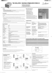
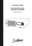
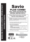
1
™
Voltshield
™
The Sollatek Switcher Range
Instruction manual
AVS 13/15 MICRO
AVS 13RL MICRO
AVS30 MICRO
AVS100
AVS3P-0
AVS303
Important: This manual contains important safety instructions.
Keep this manual handy for reference.
INTRODUCTION
Without doubt, power interruptions cause major problems for home and business
computing. An unpredictable power supply can lead to worrying problems such as
surges, spikes, lightning strikes, brown-outs, power-cuts (black-outs), power-back
surges, mains over-voltage, and complete failure - all of which can damage electrical
and electronic equipment. If any of these should occur, there’s a strong chance you
will suffer from loss of critical data, lowered productivity and even damage to your
expensive equipment.
Sollatek encompasses a wide range of power protection products for use in many
different industries where clean, regulated mains power is critical to their continued
operation.
For more information on our range of power protection products, contact us now.
2
THE SOLLATEK
AUTOMATIC VOLTAGE SWITCHER (AVS) RANGE
The Sollatek Voltshield (AVS) range prevents damage to equipment from over and
under voltage levels of any duration. They work by disconnecting power when
voltage levels exceed set parameters. Reconnection takes place when power
returns to normal.
Fully automatic in operation. All these products provide power-back surge
protection as standard by their in-built start-up delay and voltage monitoring.
Additionally, all models include surge and spike protection.
Contents
The Sollatek AVS13/13RL/15 micro
p.4-5
The Sollatek AVS30 micro
p.6-9
The Sollatek AVS100
p.10-11
The Sollatek AVS3P-0
p.12-13
The Sollatek AVS303
p.14-15
Comparison chart
p.16-17
Power problems
p.18-19
3
AVS13 micro, AVS13 RL micro, AVS15 micro
The AVS is an Automatic Voltage Switcher rated at 13 Amps
(AVS13) or 15Amps (AVS15). The AVS will switch off the equipment
connected to it if the mains power goes outside preset acceptable
limits and will re-connect -automatically* - when the mains power
returns to normal. Re-connection takes place after a delay to ensure
stability of the mains.
This new version of the AVS has a built-in micro-processor that has
added advanced features to the product. These include;
1) Five voltage indicators
The power supply is good and the load is connected
Hi The AVS has detected that the mains voltage is too high
and therefore dangerous to your equipment. The AVS
has disconnected the power supply .
Power supply has returned to normal (after an overvoltage condition - see above). The AVS is waiting before
the power supply is restored to your equipment.
Power supply has returned to normal (after an undervoltage condition - see below). The AVS is waiting before
the power supply is restored to your equipment.
Lo The AVS has detected low voltage condition and has
disconnected the power to your equipment to protect
against it.
* unless set to MANUAL on the Time delay Dial
2) Time Delay dial
By adjusting the dial, you can set the start-up delay (after first connecting and after re-connection
in case of over or under-voltage) from 15 Seconds to 3 minutes (AVS13) or 1.5 minute to 5 minutes
(AVS15). Alternatively you can pre-set to MANUAL. MANUAL indicates that the AVS will not connect
your load until you press the LOAD ON/OFF switch.
Tip: Use MANUAL setting if you do not want equipment to automatically re-start for example if you
do not wish the Air-conditioner to re-connect automatically after a power cut.
3) LOAD ON/OFF Switch
Using this button,
you can switch your equipment on or off. If the switch is in the off position
(Light bulb off), press the switch to turn the equipment on. PLEASE NOTE THAT THE EQUIPMENT
WILL BE CONNECTED AFTER THE DELAY HAS PASSED AS SET BY THE TIME DELAY DIAL.
4
SPECIFICATIONS
Model
AVS13
AVS13RL
AVS15
13
13
15
Current (Amps)
Nominal voltage(V)
230
230
230
Wait time (mins)
adjustable
adjustable
adjustable
15 secs-3mins
15 secs-3mins
1.5mins-5mins
Under-voltage disconnect(V)
185
185
185
Over-voltage disconnect(V)
260
260
260
Hysteresis(V)
3-7
3-7
3-7
Socket type
UK13A (BS1363)
UK13A (BS1363)
UK15A
unfused plug
Fused plug
Yes. 13Amp
Yes. 13Amp
No
RFI protection
No
Yes
No
Attenuation(db)
N/A
20@100Khz,50@1Mhz
N/A
35@10Mhz
Transient suppression
Yes(>6.5kA)
Yes(>6.5kA)
Yes(>6.5kA)
Spike protection(J)
160
160
160
OPERATION:
1. Make sure that your load does not exceed the rating of the AVS.
2. The limits of the AVS are pre-set at the factory (i.e. The AVS13 is 185-260 volts).
If different limits are required, please refer to your dealer.
3. Plug your appliance into the AVS.
4. The LEDs on the front indicate the state of the AVS (see facing page for full details).
5. It is recommended that the AVS is kept switched on, and the appliance switched on and off to
prevent activating the time delay every time the appliance is switched on.
6. The plug connected to the AVS13 is fused at 13Amps. If the unit stops working and no LEDs are
lit on the front of the unit check that the fuse is intact. If not, replace with a 13Amp HBC fuse. Caution: Before replacing fuse or resetting the circuit breaker, ensure that the load does not exceed
the recommended rating of the AVS.
5
AVS30 micro
The AVS30 micro is a single phase Automatic Voltage Switcher rated at
30 Amps. The AVS will switch off the equipment connected to it if the
mains power goes outside pre-set acceptable limits, and will reconnect
automatically when the mains power returns to normal. Reconnection
takes place after a delay, to ensure stability of the mains.
The new version of the AVS has a built-in microprocessor that adds
advanced features. These include:
Five LEDs accurately display the status
of the AVS in the following symmetrical
traffic light design:
OFF
Wait
HIGH
ON
Wait
OFF
LOW
LED Colour Indicating Red High incoming voltage Load Status
Yellow AVS is in wait state after a high voltage transitionOFF
OFF
Green Mains normal Yellow AVS is in wait state after a low voltage transitionOFF
ON
Red Low incoming voltage OFF
By adding microprocessor control to the AVS30, you can enjoy advanced functions which include:
* Variable time delay
* Variable Low voltage disconnect level
* Variable High voltage disconnect level
* Variable Blind time. Response time to under voltage disconnect
* Intelligent time delay
All these new features can be set at installation time.
* The AVS30 Micro has a reset button on the front panel. This button will eliminate the delay time.
* 5 LEDs to indicate the state of the mains supply.
6
OPERATION
1. Make sure that your load does not exceed the rating of the AVS which is 30Amps.
2. The limits of the AVS as a standard are set for a window of 190-260 volts.
3. The AVS has to be wired to the mains supply and to the equipment it is supplying.
Please refer to the wiring diagram on page 9.
4. On first switching on, there will be no output for the wait time of approximately three minutes
while the AVS monitors the mains.
a) To by-pass the wait time, press the re-set button on the front panel of the AVS30.
b) If a different wait time is required, then change the settings on potentiometer marked
WAIT. Settings are available in increments up to 10 minutes.
You can also set the WAIT dial to MAN. While on MAN the AVS30 will not reconnect the mains
unless the Reset button is pressed. For that period the yellow LED indicates that the mains are
within acceptable limits, after which the green LED goes on and the load is connected.
5. A different blind time can be set if a different undervoltage disconnect limit is required.
Under voltage blind time means the AVS ignores any undervoltage conditions during this time.
The AVS will not switch off unless the under voltage last longer than the blind time.
6. It is recommended that the AVS is kept switched on, and the appliance switched on and off to
prevent activating the time delay every time the appliance is switched on.
SPECIFICATIONS
Model AVS30micro
Current (Amps)
Nominal voltage(V)
Wait time (mins)
Under-voltage disconnect(V)
Over-voltage disconnect(V)
Hysteresis(V)
Socket type
Fused plug
RFI protection
Transient suppression
Spike protection(J)
110V
230V
30
110
10 secs to 10mins+manual
75-110
110-150+off
3-5
direct via brass screw terminal
N/A
No
Yes >6.5kA
80
30
230
10 secs to 10mins+manual
150-230
230-300+off
3-5
direct via brass screw terminal
N/A
No
Yes >6.5kA
160
7
CONNECTION:
CAUTION: IF THE AVS IS ALREADY WIRED, MAKE SURE IT IS DISCONNECTED FROM THE MAINS
BEFORE YOU DO ANY OF THE FOLLOWING;
1. Remove the bottom cover to obtain access to connection terminals. To remove bottom cover
remove the two white caps and then undo the two screws.
2. Remove the two cable glands and then re-insert them so that the cable gland is external.
3. Insert cable from the mains supply through the cable glands of the AVS30 and connect to the
Connector terminals. (Refer to connection terminals layout diagram on next page).
4. Insert cable to appliance through the Cordgrip Bush and connect to the Connector terminals
5. Tighten the Cordgrip Bushes and return the front cover and two screws and screw caps.
PLEASE ENSURE NOT TO TIGHTEN CONNECTION TERMINALS EXCESSIVELY.
NOTES:
* In the upper compartment of the AVS, you will find a fuse (see diagram overleaf). The fuse is not for the load. It is a spike protection fuse. Replace if it gets damaged. (0.5A Anti Surge).
To gain access to the upper compartment, ENSURE THAT THE AVS30 IS NOT CONNECTED TO
THE MAINS. Remove the screws from the back.
* The AVS must be mounted securely on a wall. Place it over one screw at the top and then use
the two mounting holes in the terminal compartment.
* The supply to the AVS30 must be fitted with a 30A HBC fuse or less.
8
AVS30 CONNECTION TERMINALS LAYOUT
AVS30 INPUT
L (Live) to L
N (Neutral) to N
E (Earth) to E
AVS30 OUTPUT
L (Live) to L out
N (Neutral) to N out
E (Earth) to E out if used
spike protection fuse
9
AVS100
The is AVS100 is a single phase Automatic Voltage Switcher rated at 100 Amps.
If the voltage goes above or below the pre-set limits (the ‘window’), then the
AVS100 will switch off. Once the voltage returns within the window limits,
the AVS will wait for a pre-set time, continuing to check the voltages, before
automatically turning the load back on.
OPERATION
1. Make sure that your load does not exceed the rating of the AVS (100 Amps for the AVS100).
2. The limits of the AVS are set for a window of 190-260 volts. If a different window is required,
please refer to your dealer.
3. The AVS has to be wired to the mains supply and to the equipment it is supplying. Please refer to
the wiring diagram on page 11.
4. On first switching on, there will be no output for the wait time of approximately three minutes
while the AVS monitors the mains voltage. If a different wait time is required, please refer to
your dealer. For that period the yellow LED indicates that the mains are within acceptable limits,
after which the green LED goes on and the load is connected. The red LED indicates that the
mains supply is outside the window, and the load is disconnected.
5. It is recommended that the AVS is kept switched on, and the appliance switched on and off to
prevent activating the time delay every time the appliance is switched on.
SPECIFICATIONS
Model AVS100
110V
Current (Amps)
100
Nominal voltage(V)
110
Wait time (mins)
3 mins
Under-voltage disconnect(V)
75-110
Over-voltage disconnect(V)
110-150+off
Hysteresis(V)3-5V
Connection
screw terminals
Fused plug
N/A
RFI protection
No
Transient suppression
Yes >6.5kA
Spike protection(J)
80
10
230V
100
230
3 mins
150-230
230-300+off
3-5V
screw terminals
N/A
No
Yes >6.5kA
160
CONNECTION:
CAUTION: IF THE AVS IS ALREADY WIRED, MAKE SURE IT IS DISCONNECTED FROM THE MAINS
BEFORE YOU DO ANY OF THE FOLLOWING;
1. Open the door to obtain access to connection terminals.
2. Insert cable from the mains supply through the cable entry at the top of the box.
AVS100 CONNECTION DIAGRAM
AVS100 INPUT
L (Live) N (Neutral) to Neutral IN terminal block
to Terminal L1 of Contactor
E (Earth) to Earth IN terminal block
3. Insert cable to appliance through cable
entry at bottom of box.
AVS100 OUTPUT
L (Live) N (Neutral) to Neutral OUT terminal block
to Terminal T1 of Contactor
E (Earth)
to Earth OUT terminal block
4. Ensure connections are secure and
close door.
NOTES:
* The fuse in the terminal compartment is
not for the load. It is a spike protection
fuse.
To replace, use a 0.5A HBC type anti-surge
20x5mm fuse.
* The AVS should be mounted securely on
a wall.
* The supply to the AVS100 must be fitted
with a 100A fuse or less.
11
AVS3P-0
The AVS3P-0 is an Automatic Voltage Switcher designed to protect three
phase loads from voltage fluctuations, over voltage, under voltage, surges,
dips and frequent start/stops. The output is a single volt-free changeover
contact, rated at 16A. This is intended to control an external contactor,
control circuit, start/stop system or alarm. If the voltage on any one phase
goes above or below the pre-set limits (the ‘window’), then the AVS
will switch off. Once the voltage returns within the window limits, the
AVS will wait for a pre-set time, continuing to check the voltages, before
automatically turning the load back on. The over voltage, under voltage and
delay settings are all adjustable using controls in the terminal compartment of the AVS3P.
The standard window that is considered acceptable is 185V-260V(320V-450V three phase).
Outside these limits electronic and electrical equipment are likely to be damaged.
Five LEDs accurately display the status
of the AVS in the following symmetrical
traffic light design:
OFF
Wait
HIGH
ON
Wait
OFF
LOW
LED Colour Indicating Red High incoming voltage Load Status
Yellow AVS is in wait state after a high voltage transitionOFF
OFF
Green Mains normal Yellow AVS is in wait state after a low voltage transitionOFF
ON
Red Low incoming voltage OFF
OPERATION
1. Connect the AVS in accordance with the wiring diagram opposite (fig 1). Ensure that the R, S
& T sensing connections to the AVS come from the supply side of the contactor. Note: a good
neutral connection must be provided from the supply.
2.
The output from the AVS is a changeover relay with volt-free contacts. There is a common (C),
a normally open (NO) and normally closed (NC) contacts. When the AVS3P-0 is in the Red or
Amber condition then C is connected to NC. When the AVS3P-0 displays Green then C is
connected to NO. Make sure that the control current you wish to switch does not exceed the
rating of the AVS3P-0 relay (max 16Amps).
3.
If the AVS is the only thing to control the contactor (or load, or alarm, etc), then the ‘C’ and ‘NO’
AVS contacts can be used to connect power to the contactor coil (method A). If however, there
are other circuits/equipment that also must control the contactor, then the AVS contacts can be
used to interrupt the contactor coil supply from there (method B) or used in conjunction with a
start/stop or other system, e.g. method C.
12
4.
Set limits of the AVS3P-0 using the thumb-wheel adjustment inside the terminal compartment.
Ensure that limits set are safe for the load being protected. For example: Low =185V and High =
260V is normally considered safe for most equipment but you should check with the equipment
manufacturer’s information.
5.
Set the time delay control using the thumb-wheel adjustment inside the terminal compartment.
This will depend on your load and how it is operated. As a general guide, compressors and
refrigeration equipment will need at least 3 minutes; motors, pumps, etc should not be started
too frequently so may be 2 minutes minimum, electronic loads 0.5 minutes. The ‘Off’ position
gives just 10 seconds. The equipment manufacturer should be consulted on the best setting.
6.
At first switching on, there will be no output during the Delay period. For that period the yellow
LED indicates that the mains supply is within acceptable limits, after which the green LED goes
on and the output relay changes state to turn the load on.
SPECIFICATIONS
Model AVS3P-0
115V240V
Current (Amps)
16A@230V 16A@230V
Nominal voltage(V)
115/127V
230/240V
Wait time (mins)
10 secs to 10mins
10 secs to 10mins
Window limits
adjustable
adjustable
Hysteresis(V)
2
4
Socket type
direct via brass screw terminal
Fused plug
N/A
N/A
Transient suppression
Yes
Yes
Spike protection(J)
80J@115V
160J@230V
Max supply (phase to neutral)
160V
320V
(Option B)
N C N R S T N
C
O
Live from
other control
L1 L2 L3
(Option A)
Live to Contactor Coil
(Option C)
N C N R S T N
C
O
To Stop Control
From 24V DC
To Start Control
AVS3P-0
Contactor
N C N R S T N
C
O
A2
A1
N
T1 T2 T3
Diagram three
Three Phase Sense Wires
Switched Live to Contactor Coil
13
To The Load
Figure 1.
AVS3P-0
wiring
diagram
AVS303
The AVS303 is a Three Phase Automatic Voltage Switcher which
protects against over voltage and under voltage on any one of the
three phases as well as loss of one or more phases. Indication and/or
disconnection as a result of mains frequency error or phase sequence
error is available as an option.
The AVS303 incorporates a contactor to switch the full load current.
The AVS303-xx is available in different sizes ranging from 23Amps to
1250Amps (the -xx relates to the model number, ie: AVS303-23 is a 23Amp
per phase AVS303).
The options for the AVS303 are:
Frequency error (OPT/01)
Phase sequence error (OPT/02)
Or both (OPT/03)
If using the 'R' firmware option which provides Phase Rotation Error, it may be necessary to swap
any two of the incoming phase connections to obtain the desired phase order.
OPERATION
1. Make sure that your load does not exceed the rating of the AVS303.
2.
The limits of the AVS303 are set for a window of 190-260 volts line to neutral. If a
different window is required, please refer to your dealer.
3.
Connections of the three phases from the mains (INCOMING CABLE) and to the
load (OUTGOING CABLE) are made to the contactor. It is essential that the incoming
NEUTRAL is connected to the terminal block.
4.
On first switching on, there will be no output for approximately one minute while
the AVS303 monitors the mains. For that period the yellow LED indicates that the mains are
within acceptable limits, after which the green LED goes on and the load is connected. The red
LED indicates that the mains is outside the window, and the load is disconnected.
5.
Frequency and Phase Error indications, where fitted, are by separate red LEDs.
14
SPECIFICATIONS
AVS303
Model AVS303
Current (Amps)
Nominal voltage(V)
Wait time (mins)
Under-voltage disconnect(V)
Over-voltage disconnect(V)
Hysteresis(V)
Socket type
Fused plug
RFI protection
Transient suppression
Spike protection(J)
23 to1250
230/400
10 secs to 10 minutes
190V (150 - 230V)
260V (150 - 230V, also off)
4
direct via brass screw terminal
N/A
No
Yes >6.5kA
160
RED = phase 1
YELLOW = phase 2
BLUE = phase 3
WIRING
From the incoming mains:
1. Connect Neutral to the Neutral on the terminal block
2. Connect Phase 1 to where the RED WIRE is connected on the contactor
3. Connect Phase 2 to where the YELLOW WIRE is connected on the contactor
4. Connect Phase 3 to where the BLUE WIRE is connected on the contactor
For the outgoing mains: mirror the above connections.
15
SOLLATEK PRODUCT RANGE COMPARISON CHART
The following chart
Voltshield™
The Sollatek Switcher Range
High Voltage
Low Voltage
Basic
Lightning
Spikes/Surges
RFI / Noise
High Voltage
Low Voltage
Basic
Lightning
Spikes/Surges
RFI / Noise
High Voltage
Low Voltage
High Voltage
Low Voltage
RFI / Noise
Spikes/Surges
RFI / Noise
High Voltage
Low Voltage
dvanced
ightning
Expert
Lightning
Expert
Lightning
Power Cuts
Spikes/Surges
RFI / Noise
High Voltage
Low Voltage
Power problem
High Voltage
Low Voltage
Advanced
Lightning
RFI / Noise
High Voltage✓
Power-Back
Surges
Basic
Lightning
Advanced
Lightning
Basic
Lightning
Low Voltage
Power Cuts
✓
Basic
Lightning
Expert
Lightning
Power-Back
Surges
Power Cuts
Advanced
Lightning
Expert
Lightning
FridgeGuard
Power Cuts
✓
Expert
Lightning
✓
Expert
Lightning
Power Cuts
Power-Back
Surges
Telecom Surges
Advanced
Lightning
Expert
Lightning
✓
RFI / Noise
Telecom Surges
High Voltage
Low Voltage
Basic
Lightning
Advanced
Lightning
Advanced
Lightning
Expert
Lightning
✓
Power Cuts
Power-Back
Surges
Power-Back
Surges
Telecom Surges
Single
phase Three phase ✓
✓
✓
✓
✓
✓
✓
Telecom Surges
Expert
Lightning
Power Cuts
Power-Back
Surges
✓
Telecom Surges
✓ ✓ ✓ ✓
✓
✓
✓
✓
✓
✓
✓
✓
✓
✓
✓
✓
5
5
5
7
5
13/15
up to 25
30
100
23 to 1250
✓ ✓ ✓ ✓ ✓ ✓ ✓ ✓ ✓ ✓
Plug/socket
Plug/socket
Plug/socket
Plug/socket
+ data
Plug/socket
Direct wiring
Direct wiring
Direct wiring
Direct wiring
✓
Power-Back
Surges
Telecom Surges
Connect Plug/socket
by
Suitable
for
✓
✓ Amps Power Cuts
✓
✓
Telecom Surges
✓
✓
Power-Back
Surges
Automatic
Voltage
Switcher AVS303
✓
✓
Power Cuts
Automatic
Voltage
Switcher AVS100
✓
Expert
Lightning
✓
Power-Back
Surges
Power Cuts
Automatic
Voltage
Switcher AVS30
✓
Power Cuts
Telecom Surges
✓
✓
Expert
Lightning
Power-Back
Surges
Telecom Surges
✓
Advanced
Lightning
Automatic
A/C Guard
Voltage
AVS13/15
Telecom Surges
Switcher
Power-Back
Surges
✓
✓
Telecom Surges
✓
Power-Back
Surges
Power Cuts
Telecom Surges
(AVS13RL only)
ower Cuts
Power-Back
Surges
Power Cuts
VoltGuardTelecom Surges
LightningGuard
Power-Back
Surges
Advanced
Lightning
Basic
Lightning
Telecom Surges
Telecom Surges
Lightning
Low Voltage
Expert
Lightning
Power-Back
Surges
Power Cuts
Basic
Lightning
TVGuardExpert
High Voltage
Basic
Lightning
Spikes/Surges
Advanced
Lightning
HiVoltGuard Advanced
Basic
Lightning
Lightning
Spikes/Surges
Power-Back
Expert
Power
Cuts
Prevents
damage to
equipment
from over or Telecom
underSurges
voltage levels of long duration. Works by disconnecting power when voltage level exceeds set parameters.
Surges
Lightning
Reconnects again when power returns inside parameters for a pre-set period. Fully automatic operation. All switchers include other protection features.
Advanced
Lightning
RFI / Noise
TV VCR HiFi
radio etc
TV LCD/Plasma Fridge Freezer
screens
Cooler etc
VCR HiFi Fax
machines etc
TV VCR HiFi
Radio Fridge
Freezer etc
Telecoms
Any electrical
equipment
or electronic
internet
equipment
Broadband PC (incl.air con)
modem data
etc
16
Air
conditioning
equipment
Any electrical or electronic
equipment
(incl.air con)
Air con mac
industria
gives an overview of most of the Sollatek range of products and the protection they offer.
Voltsure™
Voltright™
Voltsafe™
The Sollatek Suppressor Range
The Sollatek Regulator Range
The Sollatek UPS Range
Stops short-term disturbances, created by lightning strikes, power stations or nearby
equipment switching on & off, from causing damage.
Ensures equipment can still operate although the
voltage level is outside its ’normal’ range, by automatic
correction within set levels.
Keeps equipment operating
temporarily in a blackout
by using stand-by battery power
Automatic
Voltage
Switcher AVS3P-0
SpikeGuard
CommsGuard
✓
✓
PureAC
Distribution
Surge
Protector
Sollatek
Voltage
Stabiliser
Automatic
Voltage
Regulator
Automatic
Voltage
Regulator 3p
Ultima 400 - 800
Ultima 1000 - 2000
✓
✓
✓
✓
✓
✓
✓
✓
✓
✓
✓
✓
✓
✓
MultiGuard
(optional)
(MG4, MG5)
(optional)
(optional)
✓
✓
✓
✓
✓
✓
✓
✓
✓
✓
✓
✓
✓
✓
✓
✓
✓
✓
✓
✓
✓
✓
✓
✓
✓
✓
(optional)
✓
✓
✓
✓
✓
✓
unlimited
1 to 75
1 to 400
20 to 3000
1.5 to 8
1.5 to 8
✓
✓
Plug/socket
Plug/socket
(MG3, MG5)
unlimited
13
13
13
3 to13
✓ ✓ ✓ ✓ ✓ ✓ ✓
✓
✓
✓
✓
Direct wiring
Plug/socket
Plug/socket
+ data
Plug/socket
Plug/socket
Direct wiring
chinery for
al plants
Any electrical
CPU Fax
Any electrical
or electronic Modem Phone or electronic
equipment
equipment
equipment
on multi way
strip
Plug/socket
Plug/socket
+direct wiring +direct wiring
Any electrical Whole building Any electrical
or electronic
electrical or
or electronic
equipment
electronic
equipment
equipment
1 or 3 phase
17
Plug/socket
Sensitive electrical or
electronic equipment
Computers, Servers,
Telecom and any vital
equipment.
kes/Surges
/ Noise
RFI / Noise
/ Noise
h Voltage
Low Voltage
Basic
Lightning
Advanced
Lightning
Expert
Lightning
All electrical and electronic equipment, connected to the mains supply is at risk of
being damaged from spikes, surges, lightning, brown-outs, power-cuts (blackouts),
power back surges, and over-voltage. The following is a summary of the main types of
Advanced
Expert
Basicthese affect
Power Cuts
High Voltage
Lowcauses
Voltage and how
power
problems,
electrical andLightning
electronic equipment.
Lightning
Lightning
Spikes/Surges
kes/Surges
h Voltage
High Voltage
POWER PROBLEMS
AND THEIR ASSOCIATED CAUSES
RFI / Noise
Low Voltage
High Voltage
Low Voltage
RFI / Noise
High Voltage
Low Voltage
Basic
Lightning
Advanced
Lightning
Power Cuts
Power-Back
Surges
Expert
Lightning
Spikes/Surge: Very short, (one millisecond) event of very high surge in voltage to
thousands of volts and amps. Spikes are common in all parts of the world and repeated
Expert
Basic equipmentAdvanced
Power Cuts
High Voltage
Low Voltage
exposure
damage electronic
and
data.Power-Back
Advanced
Expert
Basic to spikes will
Powercorrupt
Cuts
Telecom Surge
Lightning
Lightning
Lightning
Lightning
Lightning
Lightning
What
causes it? Switching
on/off of nearby
equipment, lightning, motors Surges
starting etc.
RFI (Radio Frequency Interference)/Noise: High frequency disturbances that occur
within a short period of time (milliseconds). RFI & noise are very common in all parts of
the world and are the main cause of data corruption.
What causes it? Generated by high frequency noise from nearby equipment like
Advanced
Experton/off of certain
Power-Back
Basic
Power Cuts
Voltage
TV,Low
radio
equipment,Lightning
transmitters,
mobile
phones, switching
loads,
Lightning
Lightning
Surges
fluorescent lights, motor speed controls, light dimmers.
Over-Voltage: Long duration (milliseconds, seconds, minutes, hours or days) rise in
the voltage above acceptable limits. Depending on the level of the over-voltage, the
damage can be instantaneous, severe and irreparable.
What causes it? On return of mains supply after power cuts, under-sized utility
Advanced
Expert
Power-Back
Basic
Power Cuts
oscillating
and over-voltage
or accidental
(e.g.
Lightningof brown-outs
Lightning
Surges
Lightningbetween periods
accidental connection between two phases).
Brown-Out: Long duration of low voltage (milliseconds to seconds, minutes, hours or
days). Very common in parts of the world especially where the power utilities are overstretched. Prolonged and frequent brownouts cause the equipment to malfunction
or not work at all. Repeated episodes are certain to cause damage. Motors and
compressors (and therefore fridges, freezers, coolers, air-conditioners and pumps) are
especially at risk. In time, damage is certain.
What causes it? Most commonly an over-stretched utility, especially in areas of poor
power distribution infra-structure and remote areas. Common in dry seasons where
water is used for electricity generation.
18
Telecom Surg
pert
ning
r Cuts
Voltage
r-Back
pert
ges
htning
er Cuts
er-Back
rges
Power Cuts
Power-Back
Basic
Surges
Lightning
Telecom Surges
Power Cuts
Power-Back
Surges
Telecom Surges
Power-Back
Surges
Telecom Surges
Advanced
Lightning
Telecom Surges
Expert
Lightning
Power Cuts
Power-Back
Surges
Telecom Surges
Basic Lightning: Direct or nearby strikes can cause minor problems or severe
disturbances and damage. Lightning produces spikes/surges, over-voltage or power
cuts.
What causes it? The surge is generated by either a direct hit, or indirectly striking
Power-Back
Telecom Surges
underground
or overhead
lines and transmitting high surges to connected equipment
Surges
in nearby buildings.
Power-cuts: Common in many countries in the world, especially in areas of frequent
voltage problems. Sudden loss of power can cause damage ranging from corruption
of data to mechanical faults as equipment is stopped while in operation.
Telecomcauses
Surges it? Power or sub station failure, breakdown in the distribution network,
What
or simply a plug being pulled out accidentally.
Power-Back Surges: These typically occur when power returns after a power-cut
and connected equipment receives a surge of electricity at an over-voltage level,
which can be very damaging (see above).
What causes it? Power back surges are created by the utility, when it restores
supply at an above normal voltage in order to compensate for the demand as
connected equipment re-starts simultaneously.
Telecom surges, spikes and lightning: Short term, high voltage and current
phenomena occurring on the telephone lines. Can cause irreparable damage to any
piece of equipment connected to the incoming line. The telephone line itself may
even be damaged or destroyed in severe cases.
What causes it? Telecom spikes are caused by lightning striking either the telephone
line directly or an object near it.
19
™
Sollatek (UK) Ltd. Sollatek House. Waterside Drive. Langley. Slough. SL3 6EZ United Kingdom
Tel: +44 (1753) 214 500 Technical support: [email protected]
Sales: [email protected] www.sollatek.com
©Sollatek (UK) Limited 2010. All Rights Reserved. SOLLATEK and
the SOLLATEK device are the trade marks of the Sollatek group of
companies.
AVS User Manual Rev 3.0 December 2009
74108407