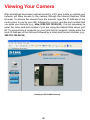
1
DCS-2000
Audio Internet Camera
Manual
Version 3.40
Building Networks for People
(10/04/04)
Contents
Contents of Package ....................................................................................... 3
Introduction ...................................................................................................... 4
Features and Benefits ..................................................................................... 4
Connections .................................................................................................... 6
Hardware Installation ....................................................................................... 8
Installation Wizard ........................................................................................... 9
Installation Wizard Screen ............................................................................ 14
Enabling UPnP for Windows XP/Me .............................................................. 17
Installing IP surveillance Software ................................................................. 21
Testing the DCS-2000 ................................................................................... 25
Security ......................................................................................................... 26
Using and Configuring the DCS-2000 with a Router ..................................... 27
Using the DCS-2000 with an Internet Browser .............................................. 33
Record Snapshots to your FTP server with Motion Detection....................... 58
Using IP surveillance Software ...................................................................... 62
Installing IP surveillance Software ..................................................... 62
Launcher .......................................................................................... 67
Monitor Program ................................................................................ 70
Scheduling ......................................................................................... 95
Playback Program ............................................................................ 103
Schedule Video Recording with Motion Detection ....................................... 118
Appendix ...................................................................................................... 121
Frequently Asked Questions ............................................................ 121
How to PING Your IP Address .......................................................... 124
Reset and Restore .......................................................................... 125
I/O Connector .................................................................................. 126
Adjusting the Camera’s Focus ........................................................ 130
Replacing the Lens .......................................................................... 131
Technical Specifications .................................................................. 132
Contacting Technical Support ..................................................................... 134
Time Zone Table .......................................................................................... 135
Warranty ...................................................................................................... 137
Registration ................................................................................................. 140
2
Package Contents
D-Link DCS-2000 Internet Camera
Power Adapter
Installation software and manual on CD
Quick Installation Guide
Camera Stand
Category 5 Ethernet Cable
If any of the above items are missing, please contact your reseller.
Note: Using a power supply with a different voltage than the one included with the
DCS-2000 will cause damage and void the warranty for this product.
Minimum System Requirements:
Internet Explorer 6.x or higher Internet Web Browser
CPU: 1.7GHz or above
(Pentium 4, 2.4Ghz plus processor with 512Mb memory and a
32Mb video card is required for multiple camera viewing and
recording in IP Surveillance)
Memory Size: 128MB
VGA card resolution: 800 x 600 or above
3
Introduction
The D-Link SECURICAM NetworkTM DCS-2000 Internet Camera is a full featured
surveillance system that connects to an Ethernet, Fast Ethernet or broadband
Internet connection to provide remote high-quality video and audio. The DCS2000 Internet Camera differs from a conventional PC Camera because it is a
stand-alone system with a built-in CPU and Web server providing a low-cost
solution capable of solving demanding security and home/office monitoring
needs. The DCS-2000 can be accessed remotely, and controlled, from any PC
or notebook computer over the Internet from anywhere in the world. Simple
installation procedures, along with the built-in Web-based interface offers easy
integration to your network environments.
Features and Benefits
The SECURICAM NetworkTM DCS-2000 Internet Camera is a stand-alone system
requiring no special hardware or software such as PC frame grabber cards.
All that is required is a computer with the Internet Explorer Web browser (version
6.x or above). Just plug in the camera and view the picture from your Internet
Camera with a valid IP Address.
Broad Range of Applications
With today’s high-speed Internet services, the Internet Camera can provide the
ideal solution for live video images over the Intranet and Internet for remote
monitoring. The DCS-2000 allows remote access from your Internet Explorer
Web browser for live image viewing and allows the administrator to manage and
control the Internet Camera anywhere and any time in the world. Apply the Internet
Camera to monitor various objects and places such as homes, offices, banks,
hospitals, child-care centers, amusement parks and other varieties of industrial
and public monitoring. The Internet Camera can also be used for intruder detection
with its motion-detection mode, capture still images and video images for archiving
and many more applications.
Supports a Variety of Platforms
Supporting TCP/IP networking, SMTP e-mail, HTTP and other Internet related
protocols, the DCS-2000 can be integrated easily into other Internet/Intranet
applications because of its standards-based features.
Web Configuration
Using the Internet Explorer Web browser, administrators can configure and
manage the Internet Camera directly from its own Web page via the Intranet or
the Internet. Up to 20 user names and passwords are permitted, with privilege
settings controlled by the administrator.
4
Features & Benefits (continued)
Powerful Surveillance and Remote Monitoring Utility
The powerful IP surveillance software application assigns an administrator
with a pre-defined user ID and password who can modify the Internet Camera
settings from the remote site via an Intranet or the Internet. Administrators are
allowed to monitor the image, record the image to a hard drive, and take
snapshots.
Connection to External Devices
Supporting auxiliary Input/Output connectors, you can connect the Internet
Camera to a variety of external devices such as IR-sensors, switches and alarm
relays. Combined with programmable alarming facilities, you can develop a variety
of security applications that are triggered on alarm-based events. The Internet
Camera provides an industry standard in/out external connector for connectivity.
Note: Use of audio or video equipment for recording the image or voice of a
person without their knowledge and consent is prohibited in certain states or
jurisdictions. Nothing herein represents a warranty or representation that the
D-Link product provided herein is suitable for the end-user’s intended use under
the applicable laws of his or her state. D-Link disclaims any liability whatsoever
for any end-user use of the D-Link product, which fails to comply with applicable
state, local, or federal laws.
5
Connections
Reset Button
DC Power Connector
Ethernet Cable Connector
Ethernet Cable Connector
I/O Connector
The DCS-2000 back panel features an RJ-45 connector for connections to
10Base-T Ethernet cabling or 100Base-TX Fast Ethernet cabling. This network
port supports the NWay protocol, allowing the Internet Camera to automatically
detect or negotiate the transmission speed of the network.
The Ethernet cable included with the DCS-2000 Internet
Camera is a Category 5 “straight through” cable. This is
the recommended cable type when the camera is
connected to a 100 Mbps Fast Ethernet network hub or
switch.
DC Power Connector
The DC power input connector is located on the DCS-2000 Internet Camera’s
back panel and is labeled DC 12V with a single socket to supply power to the
Internet Camera.
Reset Button
Reset will be initiated when the reset button is pressed once and held until the
Power LED flashes through its cycle twice.
Factory reset will be initiated when the reset button is pressed continuously
for 5 seconds or when the Power LED changes from green to red for 2
cycles. (For example you will see the LED turn to red twice, release the
reset button when the LED turns red the second time). The Power LED will
begin to flash indicating that the Internet Camera’s settings are reverting
back to the factory settings, then turn back to green. To reset the camera,
press the reset button once, and the LED will flash to orange.
6
Connections (continued)
I/O Connector
The DCS-2000 provides a terminal block with two pairs of connectors situated
on the back panel. One pair is for input and the other is for output. The I/O
connectors provide the physical interface to send and receive digital signals to
a variety of external alarm devices. Please refer to the appendix in this
manual for detailed information.
Bottom Panel
Socket for stand
Attachment socket for the Camera Stand
Located on the bottom panel of the DCS-2000, the socket is used to connect
the camera stand to the Internet Camera by attaching the screw head on the
camera stand to the Internet Camera.
Power LED
LED stands for Light-Emitting Diode.
The Power LED is positioned on the right side of the Internet Camera lens. As
soon as the power adapter is connected to the Internet camera the power LED
will flash red and green several times, the DCS-2000 is conducting a
self-test. Upon passing the self-test the LED will turn green to indicate a good
connection to an Ethernet port or red to indicate no connection has been made.
7
Hardware Installation
Connect an Ethernet cable
Connect an Ethernet cable to the network
cable connector located on the DCS-2000’s
back panel and attach it to the network.
Attach the external power supply
Attach the external power supply to the DC
power input connector located on the
DCS-2000’s back panel labeled 12VDC
and connect the other end to your wall outlet.
When you have a proper connection, the LED will turn from red to green. The
light may cycle on and off and your computer may show an intermittent loss of
connectivity, this is normal until you have configured your Internet Camera.
Attaching the Internet Camera to the Camera Stand
The Internet Camera comes with a camera
stand with a swivel ball screw head that
can be attached to the Internet Camera
bottom socket cavity. Attach the camera
stand to the Internet Camera and station it
for your application. There are holes
located in the base of the camera stand
allowing the Internet Camera to be mounted
to the ceiling, or any wall securely.
8
Installation Wizard
After you have successfully completed the hardware installation of the DCS2000 Internet Camera, it is necessary to install software to configure and operate
the camera. The first step is to install the Installation Wizard from the CD.
Installation Wizard will allow you to configure the Internet Camera to your
network.
After the Installation Wizard software program is completed, you will have an
operating and controllable Internet Camera. From your Internet Explorer Web
browser you will be able to access the video and sound from the Internet camera.
The camera has a built-in Web server. This Web server will allow the camera to
access the Internet without being attached to a computer and permits users to
view the video and audio remotely.
After running the Installation Wizard, you will be able to operate the DCS-2000
and view the camera remotely through Internet Explorer 6.x or above.
However it is necessary to install the IP surveillance software from the enclosed
CD to create a truly powerful monitoring and surveillance system. The following
section will show in detail the installation of the Installation Wizard and the IP
surveillance software.
Installing the Installation Wizard program
Insert the CD that is included with the DCS-2000 Internet Camera. The
DCS-2000 installation menu will start up automatically from the CD. If the CD
does not start up automatically (the Windows operating system can turn this
function off, for example), go to Start > Run > Type D:\Autorun (if D:\ is your cdrom drive) to access the installation menu shown below:
Click Install Software
9
Installation Wizard (continued)
Click Installation Wizard
Please wait while the
InstallShield Wizard
prepares to install.
Click Next.
10
Installation Wizard (continued)
The InstallShield will install in
the following folder. To install
into a different folder, click
Browse and select another
folder.
Click Next.
Select the Program folder
that Setup will add program
icons to. You may type a new
folder name, or select one
from the existing folders list.
Click Next.
Please wait while the
Installation Wizard is
installed.
11
Installation Wizard (continued)
Installation is now complete.
Click Finish.
To access the Installation Wizard
screen, click on the Installation
Wizard Icon on your desktop.
The opening Installation Wizard screen
will appear and show a MAC address of
the DCS-2000 and an IP Address (which
may or may not be correct depending on
what you have your DCS-2000 connected
to). If you have a DHCP* server on your
network, there will be a valid IP Address
displayed here, indicated by a “Yes”
under the assigned column.
*A DHCP server is a device that supplies
IP Addresses to its clients that are on the
same network.
IMPORTANT:
A hardware reset of the Internet Camera may be required if the Installation
Wizard cannot find the camera. To accomplish this reset, lightly insert a paper
clip (or a similar sized tool) into the reset hole on the back of the camera (see
page 6 for the location of the reset hole). The LED on the front of the camera
will begin blinking orange. When it stops the blinking cycle continue to hold in
the reset button until a second cycle of blinking red and green lights indicates a
second reset cycle has completed. This will take approximately 5-7 seconds.
12
Installation Wizard (continued)
The Installation Wizard will now show a MAC address for the DCS-2000 and
an IP address. This IP address may not be correct at this step in the installation
until you see “Yes” under the assigned column. The camera is now automatically
configured with an IP address consistent to the device it is connected to.
Select the MAC address.
Click on the Link to Selected
Devices button.
For more information regarding the functions of this screen, see the following
section titled “Installation Wizard Screen.”
After you click on the Link
to Selected Devices
button, Installation
Wizard will automatically
open your Internet
browser to the IP
Address of the DCS2000, in this example it is:
http://192.168.0.10. Your
DCS-2000 may have a
different IP Address.
You have now completed the Setup Wizard and are ready to use your
camera! You can also continue to the section titled “Installing IP
surveillance Software” (page 21) to install the IP surveillance software
before you begin to use the DCS-2000.
13
Installation Wizard Screen
The following options are available on the Installation Wizard screen by clicking
on the corresponding tab:
Search Click to search for any available
cameras to connect to the network.
Add Click to manually add a camera to
the network. A window will appear,
prompting you to enter the camera’s
IP address or domain name. A
second window will appear,
prompting you to enter the port
number.
Remove Click to remove the selected camera(s) from the network.
Uncheck All Click to uncheck all selected cameras.
Links to Selected Devices Click to link all selected devices to the network.
Setup On the initial Setup Screen you can
configure System and Date/Time
settings for each camera. Click
Next to configure Network settings
for the camera.
System Settings Enter a Camera Name and create
a Root password for the camera.
Date/Time Settings Enter the Date and Time for each
camera. These settings can also be
configured on the Tools > System
screen (page 50) when configuring
the camera via a Web browser.
14
Installation Wizard Screen (continued)
Network Settings Here users can configure the
Network Settings for the camera.
Enter the IP address, Subnet mask,
Default router IP, Primary DNS, and
Secondary DNS. Automatically, the
option to reset IP address at boot is
selected. If you would like to save
your IP address settings, make sure
to uncheck this box. These settings
can also be configured on the
Advanced > Network screen
(page 36) when configuring the
camera via a Web Browser.
Click Next and then Apply to save
the configured settings. Users can
click Previous to modify changes
or mistakes.
Upgrade The upgrade window allows users
to upload a saved firmware file. If
the firmware is older than that
currently on the camera, a screen
will appear indicating so and
prompting the user to confirm the
upload.
Package Information This displays information about the
firmware and plugin currently
installed on the camera.
15
Installation Wizard Screen (continued)
Locate the Firmware to Upgrade Indicate the location of the firmware to be uploaded to the camera.
Selected Package This displays the file name of the firmware selected for upload.
Reset to Default Click the Reset to Default tab to reset the camera’s settings to factory defaults.
About Click About to display the current
version and date.
Exit Click the Exit tab to exit the Installation Wizard screen.
16
Enabling UPnP for Windows XP/Me
UPnP is short for Universal Plug and Play, which is a networking architecture
that provides compatibility among networking equipment, software, and
peripherals. The DCS-2000 is a UPnP enabled Internet camera. If your operating
system is UPnP enabled, the device will be easier to configure. If you do not
want to use the UPnP functionality, it can be disabled by unchecking the Enabled
DDNS check box on the DDNS/UPnP settings page under “Advanced” in the
configuration menu. Use the following steps to enable UPnP (Universal Plug
and Play) settings only if you are running Windows XP/Me. If you are running
Windows 98/2000, UPnP is not available.
Go to Start >Settings.
Click Control Panel
Click Add or Remove
Programs
17
Enabling UPnP for Windows XP/Me
(continued)
Click Add/Remove
Windows Components
The following screen will
appear:
Select Networking Services
(Communications in Windows
Me
Click Details
Select Universal
Plug and Play
Click Ok
18
Enabling UPnP for Windows XP/Me
(continued)
Click Next
Please wait while Setup
configures the components.
Click Finish
19
Enabling UPnP for Windows XP/Me
(continued)
To view your DCS-2000
Internet Camera in an Internet
browser, go to your Desktop
and click My Network
Places.
Click My Network Places
Click DCS-2000-100
The last three digits (100),
represent the fourth octet of your
Internet Camera’s IP address
(in this example, 198.168.0.100).
After you click on the DCS-2000100 icon, your Internet browser
will automatically be opened to
the IP Address of the DCS-2000,
in this example it is: http://
192.168.0.100. Your DCS-2000
may have a different IP Address.
(Note: Screen shots are taken in Windows XP, similar screens will appear in Windows Me.)
20
Installing IP surveillance Software
The IP surveillance software on the CD included with the DCS-2000 Internet
Camera converts the DCS-2000 into a powerful, yet flexible, surveillance system
for home or business, with these features:
Real-time Monitoring
Video Recording to hard disk
High quality video
High compression ratio
Maximum of 16 cameras with different monitor layouts
Smart playback
Triggered event browsing
Fast database searching
Configurable automated alarms
Account password protection
Scheduled recording for each camera
Email / FTP snapshot
AVI file export
Motion detection for each camera
To install the IP surveillance software, click on Install IP surveillance Software
on the CD included with the Internet Camera. The Welcome screen appears:
Click Next
21
Installing IP surveillance Software (continued)
Click Yes
Please read the Software Licensing Agreement and click yes if you wish to
accept the agreement. Click “No” to exit the installation.
Click Next
Enter your name and company information and click “Next.”
22
Installing IP surveillance Software (continued)
Select the
destination
directory.
Click Next
Select the
program folder
the software will
be installed into.
Click Next
23
Installing IP surveillance Software (continued)
Click Next
Click Finish
The installation is complete.
24
Testing the DCS-2000 Internet
Camera
Open your Internet browser and
type in the IP address of the
DCS-2000. In this example the
address is:
http://192.168.0.100
(your DCS-2000 may have a
different IP address based on
what you used in the
Installation Wizard program.)
The window in the center of your browser is the camera image window. You
should now see a video image and hear the audio over your computer speakers
from the DCS-2000. If you are having problems please consult the FAQ section
of this manual (page 121).
25
Security
At this point it is highly recommended that you click on the Configuration button
on the Home screen, and then the Tools tab to bring you to the Admin screen.
Enter a password for security purposes.
To ensure the highest security and prevent unauthorized use of the Internet
Camera, the Administrator has the exclusive privilege to access the System
Administration settings to allow users entry and authorize privileges for all
users. The Internet Camera supports multi-level password protection/access
to the Internet Camera that can be restricted to defined users who have a User
Name and User Password, which is assigned by the Administrator.
The Administrator can release a public user name and password so that when
remote users access the Internet Camera they will have the right to view the
image transmitted by the Internet Camera.
When the Internet Camera is used for the first time, it is highly
recommended that the Administrator set the Administrator’s Password
to constrain user access to the Internet Camera since the Default
settings are Null String (no password). Once the Password is defined,
only the Administrator has access to the management of the Internet
Camera. This procedure should be done as soon as possible since the
security features of the Internet Camera will not be enabled until the
Administrator Password is defined.
26
Configuring a DCS-2000 Behind a NAT
Router or Internet Gateway
D-Link’s DCS-2000 is a versatile and cost effective Internet Camera offering
both video and audio monitoring. It can also serve as a powerful surveillance
system in security applications. The DCS-2000 can be used with any wired or
wireless router. This section explains how to view the camera from either the
Internet or from inside your internal network.
Materials Needed:
• 1 DCS-2000 Internet Camera
• 1 Ethernet Cable
• A Wired or Wireless router such as the D-Link DI-614+ Wireless Router
• Ethernet based PC for system configuration
SETTING UP THE DCS-2000 FOR USE BEHIND A ROUTER
Installing a DCS-2000 Internet Camera on your network is an easy 4–step
procedure:
Assign a local IP Address to your Internet Camera
View the Internet Camera Using Your Internet Explorer Web browser
Access the Router with Your Web browser
Open Virtual Server Ports for Your Router (Enable Remote Viewing)
This section is designed to walk you through the setup process for installing
your camera behind a router and enable remote video viewing. For the basic
setup of the DCS-2000, follow the steps outlined in the Quick Installation
Guide.
After you have completed the setup of the DCS-2000 outlined in the Quick
Installation Guide you will have an operating camera that has an assigned IP
Address. Because you are using a router to share the Internet with one or more
PCs, the IP Address assigned to the Internet Camera will be a local IP Address.
This allows viewing within your Local Area Network (LAN) until the router is
configured to allow remote viewing of the camera over the Internet.
Assign a Local IP Address for Your Camera
Run the Installation Wizard program from the CD included with the DCS-2000.
Follow the steps in the Quick Installation Guide to configure the DCS-2000.
The camera will be assigned a local IP Address that allows it to be recognized
by the router. Write down this IP Address for future reference.
27
Using & Configuring the DCS-2000 with a
NAT Router (continued)
This is the IP Address
assigned to your camera.
Write it down for later use.
192.168.0.101 is only an
example. You will probably
have a different IP Address.
View the Internet Camera using your Internet Explorer Web
browser
Run your Internet Explorer Web browser. In the address bar, type in the IP
Address that was assigned to the Internet Camera by the Installation Wizard
program. The DCS-2000 Home Page appears with a window displaying live
video from the camera. You are able to view this screen from any PC running
Internet Explorer on your LAN.
Click on the Configuration
button.
Viewing the Video on the browser to test the connection
Click on the Configuration button on the left side of the display. The Network
Configuration page displays the ports used by HTTP and Streaming audio
and video.
28
Using & Configuring the DCS-2000 with a
NAT Router (continued)
These are the port settings for
your camera. If necessary, these
ports can be changed if they are
already in use by other devices
(e.g. in a multiple camera environment).
Ports that are used by the DCS-2000
Router Set-Up and Installation
The following steps generally apply to any router that you have on your network.
The D-Link DI-614+ is used as an example to clarify the configuration process.
Configure the initial settings of the DI-614+ by following the steps outlined in the
DI-614+ Quick Installation Guide.
Access Your Router on Your Web Browser
If you have cable or DSL service, you will most likely have a dynamically
assigned WAN IP Address. ‘Dynamic’ means that your router’s WAN IP address
can change from time to time depending on your ISP. A dynamic WAN IP Address
identifies your router on the public network and allows it to access the Internet.
To find out what your router’s WAN IP Address is, go to the Status menu on
your router and locate the WAN information for your router. As shown on the
next page the WAN IP Address will be listed. This will be the address that you
will need to type in your Web browser to view your camera over the Internet.
29
Using & Configuring the DCS-2000 with a
NAT Router (continued)
Your WAN IP
Address will be
listed here.
Determine Your Router’s IP Address (WAN)
Note: Because a dynamic WAN IP can change from time to time depending on
your ISP, you may want to obtain a Static IP address from your ISP. A Static IP
address is a fixed IP address that will not change over time and will be more
convenient for you to use to access your camera from a remote location. The
Static IP Address will also allow you to access your camera attached to your
router over the Internet
Open Virtual Server Ports to Enable Remote Image Viewing
The firewall security features built into the DI-614+ router prevent users from
accessing the video from the DCS-2000 over the Internet. The router connects
to the Internet over a series of numbered ports. The ports normally used by the
DCS-2000 are blocked from access over the Internet. Therefore, these ports
need to be made accessible over the Internet. This is accomplished using the
Virtual Server function on the DI-614+ router. The Virtual Server ports used
by the camera must be opened through the router for remote access to your
camera. Virtual Server is accessed by clicking on the Advanced tab of the
router screen.
30
Using & Configuring the DCS-2000 with a
NAT Router (continued)
Follow these steps to configure your router’s Virtual Server settings:
•
•
•
•
•
•
Click Enabled.
Enter a different name for each entry.
Enter your camera’s local IP Address (e.g., 192.168.0.146 in
on page 28) in the Private IP field.
the example in step
Select Both under Protocol Type (TCP and UDP).
If you are using the default camera port settings, enter 80 into
the Public and Private Port section, click Apply.
Scheduling should be set to Always so that the camera
images can be accessed at any time.
Repeat the above steps adding ports 5001, 5002, and 5003 to both the Public
and Private Port sections. A check mark appearing before the entry name will
indicate that the ports are enabled.
Important: Some ISPs block access to port 80. Be sure to check with your ISP
so that you can open the appropriate ports accordingly. Some ISPs block traffic
on commonly used ports to conserve bandwidth. If your ISP does not pass
traffic on port 80, you will need to change the port the camera uses from 80 to
something else, such as 800. Not all routers are the same, so refer to your
user manual for specific instructions on how to open ports.
Enter valid ports in the Virtual
Servers section of your router.
Please make sure to check
the box on this line to enable
settings.
31
Viewing Your Camera
After all settings have been entered correctly, a PC user inside or outside your
network will have access to the camera through the Internet Explorer Web
browser. To access the camera from the Internet, type the IP Address of the
router given to you by your ISP, followed by a colon, and the port number that
you gave your camera (e.g., http://205.163.122.96:83). It is not necessary to
enter the colon and port number if you are using the default Web server port
80. To access from a computer on your local (home) network, simply enter the
local IP Address of the Camera followed by a colon and the port number (e.g.,
205.163.122.96:83).
http://205.163.122.96:83
Viewing the DCS-2000 Remotely
32
Using the DCS-2000 with an
Internet browser
If you are following this manual in the order it is presented, you should now have
an operating DCS-2000 Internet Camera configured with the Installer program.
You also have installed the IP surveillance software from the CD. This section
of the manual will deal with using the Internet Camera in two parts:
Using the DCS-2000 with an Internet browser and accessing
the screens to control and monitor the camera.
Using the IP surveillance software with the DCS-2000.
Open your Internet Explorer Web browser and enter the IP address for your
Internet Camera.
In the example, this address is 192.168.0.146. Your address may differ.
If a window appears
asking to install a
Verisign certificate
for authentication
Click Yes. This
allows the proprietary
MPEG4 video stream
to be recognized by
Internet Explorer.
33
Using the DCS-2000 with an Internet browser
(continued)
Home Page Screen
The image from the DCS-2000 should be visible from the Home page on your
computer monitor.
There are two
buttons on the left
side of the Home
page:
Connection Type
and Configuration.
Click on the Connection Type button to change settings related to the
connection.
Click Connection Type
34
Using the DCS-2000 with an Internet browser
(continued)
Home > Connections Screen
The following options are available
from the Connections settings
screen:
Media Option:
Option for users to disable or
enable audio when viewing video.
Protocol Option
The UDP Protocol should be
chosen for the most users.
Generally the client computer will
automatically try these protocols
in the following order, UDP -> TCP
-> HTTP.
After the client connects to the DCS-2000 successfully, the working protocol
will be displayed in “Protocol Option.” The chosen protocol will be recorded in
the user’s PC and used for the next connection. If the network environment is
changed or users want to let the Web browser automatically detect the protocol,
select UDP manually and click Save to change the setting and return Home to
reconnect with the new setting.
Options:
UDP Protocol - Offers the highest image and video quality.
However, packet losses will diminish image quality when bandwidth
becomes restricted.
TCP Protocol - Packet loss is less likely to occur compared to UDP
when bandwidth is restricted.
HTTP Protocol - If the network is protected by a firewall and it opens
HTTP port (80) only, HTTP protocol must be selected. In this mode,
audio is disabled and only video can be viewed. TCP and UDP
connections will not be available to remote users if all four ports have
not been forwarded (as shown on page 30). Only the HTTP port must
be forwarded for remote users to make an HTTP connection (video
only).
Click the Home tab to return to the DCS-2000 Home page.
35
Using the DCS-2000 with an Internet browser
(continued)
Home > Configuration
Click on the Configuration button on the Home page:
Click Configuration
There are 5 tabs across the top of the Configuration screen. From each tab,
different elements of the DCS-2000 can be configured. The Advanced tab is
the default screen in Configuration and Network is the default screen under
Advanced.
Any changes made to these settings will
require the system to restart. Make sure
every field is correct before clicking on
Apply.
36
Using the DCS-2000 with an Internet browser
(continued)
Configuration > Advanced > Network
Reset IP Address at next boot
Once the DCS-2000 is configured, this box should be unchecked at all times. If
the box has been checked and the connection is lost, run Installation Wizard
to find the camera’s IP address.
General
IP address -
Necessary for network identification.
Subnet mask -
Used to determine if the destination is in the same
subnet. The default value is “255.255.255.0.”
Default router -
The router used to forward frames to destinations
in a different subnet. Invalid router settings will
cause the failure of transmissions to different
subnets.
Primary DNS -
Primary domain name server that translates names
to IP addresses.
Secondary DNS -
Secondary domain name server to backup the
primary one.
SMTP
SMTP (mail) server 1 -
The domain name or IP address of external mail
server.
SMTP account name 1 -
The user name used to log into your e-mail
account (e.g. jdoe or [email protected]
depending on your ISP).
SMTP password 1 -
The password used to log into your e-mail
account. (The password will appear as dots
instead of entered characters.)
Recipient email address 1 - The e-mail address of recipients for snapshots
or a system log file. Multiple recipients must be
separated by a semicolon “;”
SMTP(mail) server 2 The domain name or IP address of a secondary
mail server used only if the primary mail server
is unreachable.
37
Using the DCS-2000 with an Internet browser
(continued)
Configuration > Advanced >Network Settings (continued)
SMTP account name 2 -
The user name for the second SMTP server.
SMTP password 2 -
The password used to log into the second e-mail
account. (The password will appear as dots
instead of entered characters.)
Recipient email address 2 - The e-mail address of recipients for the secondary
server.
Return email address -
The return e-mail address to use if the snapshot
or system log e-mail fails to send. (This
address should be within the SMTP server’s
domain for authentication purposes.)
FTP Settings
Local FTP server port -
Can be other than default port 21. If you find that
you want to change the port to a number other
than 21, you will need to specify the port when
connecting to the FTP server. For example
FTP://68.5.1.81:60 (if you are to use port 60 for
your FTP server port)
1st FTP server -
The domain name or IP address of the external
FTP server. The following user settings must be
correctly configured for remote access.
1st FTP user name -
Granted user name on the external FTP server.
1st FTP password -
Granted password on the external FTP server.
1st FTP remote folder -
Granted folder on the external FTP server. The
string must conform to the external FTP server.
Some FTP servers cannot accept a preceding
slash symbol before the path if there is no virtual
path mapping. Refer to the instructions of the
external FTP server for details. The folder
privilege must be open for upload.
38
Using the DCS-2000 with an Internet browser
(continued)
Primary FTP Passive
Mode-
If the DCS-2000 is located inside the network
protected by firewall, a data connection for FTP
may be prohibited. Passive mode FTP can bypass
the rule and succeed to upload snapshots. If the
passive mode is selected, the DCS-2000 can
automatically attempt for an active mode if the
external FTP server does not support passive
mode.
2nd FTP server -
The domain name or IP address of the external
FTP server. Note that the 2nd FTP server will only
be used if the 1st FTP server is unavailable. If
the image upload to the 1st FTP server is
successful, no attempts will be made to connect
to the 2nd FTP server.
2nd FTP user name -
Granted user name on the backup FTP server.
2nd FTP password -
Granted password on the backup FTP server.
2nd FTP remote folder -
Granted folder on the backup FTP server.
Secondary FTP passive
Mode -
Passive mode setting for the backup FTP server.
HTTP Settings
HTTP Port-
Can be set to other than the default port 80. When
the administrator changes the HTTP port of the
DCS-2000 (which has an IP Address of
192.168.0.100) from 80 to 8080, users must type
“http://192.168.0.100:8080” in the Web browser
instead of “http://192.168.0.100”.
Click Apply to make
changes effective
39
Using the DCS-2000 with an Internet browser
(continued)
Streaming Screen under “Advanced Network”
Control channel port -
Can be set to a port other than the default port
5001. A corresponding port must be opened on
your firewall.
Audio channel port -
Can be set to a port other than the default port
5002. A corresponding port must be opened on
your firewall.
Video channel port -
Can be set to a port other than the default port
5003. A corresponding port must be opened on
your firewall.
Improve audio quality
in low bandwidth
environment -
In a low bandwidth network environment you can
check this option to improve audio quality by
sacrificing some real-time synchronization.
Click Apply to make
changes effective
40
Using the DCS-2000 with an Internet browser
(continued)
Configuration > Advanced > DDNS & UPnP
Click the DDNS & UPnP button from the Configuration screen to access DDNS
& UPnP settings.
Click DDNS & UPnP
Dynamic DNS (DDNS)
Dynamic DNS (Domain Name Service) is a method of keeping a domain name
linked to a changing (dynamic) IP address. With most Cable and DSL
connections, you are assigned a dynamic IP address and that address is used
only for the duration of that specific connection. With the DCS-2000, you can
set up your DDNS service and the DCS-2000 will automatically update your
DDNS server every time it receives a different IP address. Depending on the
service, this update may take a few hours.
41
Using the DCS-2000 with an Internet browser
(continued)
Configuration > Advanced > DDNS & UPnP (Continued)
Enable DDNS -
Click to enable the DDNS function.
Provider-
Select your Dynamic DNS provider from the pull
down menu.
Host name-
Enter the host name of the DDNS server.
Username/E-mail-
Enter your username or e-mail used to connect to
the DDNS server.
Password/Key-
Enter your password or key used to connect to
the DDNS server.
UPnP
UPnP is short for Universal Plug and Play, which is a networking architecture
that provides compatibility among networking equipment, software, and
peripherals. The DCS-2000 is a UPnP enabled internet camera. If your operating
system is UPnP enabled, the device will be easier to configure. If you do not
want to use the UPnP functionality, it can be disabled by unselecting the Enable
UPnP check box.
Click Apply to make
changes effective
42
Using the DCS-2000 with an Internet browser
(continued)
Invalid settings may cause the DCS-2000 to not respond. Change the
configurations only if necessary. Consult with your network administrator
or your Internet Service Provider (ISP) if you do not have the necessary
information. If you cannot connect to the camera, refer to page 125 for
camera reset and restore factory settings procedures.
Configuration > Advanced > Video
Click the video button from the Configuration screen to access video settings
that affect how the video image appears.
Click Video
Text on video -
Text will be displayed in the black bar above the video
window with the timestamp. The timestamp is
captured from the date and time of the DCS-2000
and is maintained by a built-in real-time clock.
43
Using the DCS-2000 with an Internet browser
(continued)
Configuration > Advanced > Video (Continued)
Color -
Select the option for color or monochrome video
display.
Size -
Three options exist for the sizes of the video display.
You can select between 176x120/176x144,
352x240/352x288, or 704x480/401x576. The first
value represents the PAL format of video and the
second value represents the NTSC format. In
704x480/401x576 mode, the frame rate will be
reduced to 10fps and increased to 30fps
automatically when it is switched back to a lower
image size.
Power line frequency
(for fluorescent light)
Fluorescent lights may intermittently cause a
flashing image depending on the AC power line
frequency. Change the frequency setting to
eliminate a flashing image when the light source is
fluorescent light.
Maximum frame rate-
Limits the maximum refresh frame rate. The frame
rate is used with the Video quality control setting
(below) to optimize bandwidth utilization and video
quality.
Video quality control-
To fix the bandwidth utilization regardless of the
video quality, choose Fix bit rate and select the
desired bandwidth. The video quality may be reduced
in order to send maximum frames with limited
bandwidth, especially when images change
drastically. For higher video detail regardless of the
bandwidth selection, select Fix quality and select
a quality level. This setting will utilize more bandwidth
to send the maximum frames when images change
drastically.
Flip -
Vertically rotate the video.
44
Using the DCS-2000 with an Internet browser
(continued)
Configuration > Advanced > Video Settings (continued)
Mirror -
Horizontally rotate the video. Check both flip and
mirror if the DCS-2000 is to be installed upside
down.
White balance -
Choose the suitable option for the best color
temperature.
Click Apply to make
changes effective
Recommendations for setting video for the best
performance:
“Best performance” means the image refresh rate should be the fastest possible
and the video quality should be the best possible at the lowest network bandwidth
possible. Three factors, Maximum frame rate, Fix bit rate, and Fix quality in
the Video configuration page, are related to the performance.
Recording settings for real-time motion images
To achieve a real-time visual effect, the network bandwidth should be large
enough to transmit 20 image frames per second (fps) or more. If you are on a
broadband network over 1 Mbps, you can choose Fix bit Rate to 1000Kbps or
1200Kbps, or choose Fix quality to achieve the maximum frames. The maximum
frame rate is 25 in 50Hz system and 30 in 60Hz system. If your network bandwidth
is more than 384Kbps, you can adjust Fix bit rate according to your bandwidth
and set the maximum frame rate of 25 to 30. If the images vary dramatically in
your environment, you may slow down the maximum frame rate to 20 to decrease
the transmitted data for better video quality. Since the human eye could not
easily differentiate between 20 and 25 or 30 frames per second, the slower
frame rate will not be noticed. If your network bandwidth is below 384 Kbps, you
should adjust the bit rate according to your bandwidth and experiment to allow
for the best frame rate that can be achieved. The faster frame rate in a slow
network will blur the images. You may also try to choose 352x240/352x288 in
size option for better images or 704x480/704x576 for larger image size.
Because the network has burst constraints and everyone’s environment is not
the same, any poor connection will impair normal performance.
45
Using the DCS-2000 with an Internet browser
(continued)
Recommendations for setting video for the best
performance (continued):
Recording settings for clear identification for each image
To have the best video quality, you should set Fix quality to detailed or excellent
and tune the Maximum frame rate to suit your network bandwidth. If you get
some broken pictures in a slow network, you can choose TCP protocol in
Connection type for more accurate transmission but the received image may
have lags. Note that any slow connection with multiple users will impair
performance.
Recording settings to compromise between real-time and clear
images
If you have a broadband network, set Fix quality to Good, or better, rather than
setting the Bit rate. Otherwise fix the bandwidth to accommodate your actual
network speed and set the frame rate to 30. If the images quality is low, select
the lower frame rate above 15. If the image is still not improved, select a lower
bit rate.
Configuration > Advanced > Image Setting
Click Image Setting
46
Using the DCS-2000 with an Internet browser
(continued)
Configuration > Advanced > Image Setting (continued)
Click the image setting button from the configuration screen to access additional
settings that affect how the video image appears.
From this screen you can fine tune the video image.
Image Brightness, Contrast, Saturation and Hue are all adjusted in the same
manner. For each video compensation you can set from among eleven levels
ranged from -5 to +5.
You may press
to fine-tune the image and see what effect the setting will
have on the image. When the image is acceptable, press
to store the
to recall the original settings.
image settings, or
Configuration > Advanced > Motion Detection
Click the Motion Detection button from the Configuration screen to access
settings that effect how the DCS-2000 Internet Camera can serve as a security
device by recording only when motion is detected.
Click Motion Detection
47
Using the DCS-2000 with an Internet browser
(continued)
Configuration > Advanced >Motion Detection (continued)
Enable motion detection - Check this option to turn on the motion detection.
Window Name -
The text entered here will show at the top of the
motion window.
Sensitivity -
Sets the measurable difference between two
sequential images that would indicate motion.
Percentage -
Sets the amount of motion in the window being
monitored that is required to initiate a motion
detected alert. If this is set to 100%, motion is
detected within the whole window to trigger a
snapshot.
Note:
Setting a higher sensitivity and a lower
percentage will make any motion more easily
detected.
New -
Click to add a new window. A maximum of three
motion windows can be opened simultaneously.
Use your mouse to drag the window frame to
resize or the title bar to move. Clicking on the ‘x’
at the upper right corner of the window will close
the window.
Save -
Saves the related settings of that window.
To display motion detection, a graphic bar will rise or fall depending on the
image variation.
A green bar means the image variation is under the monitoring level, and no
motion detection alert is triggered. A red bar means the image variation is over
the monitoring level and a motion detected alert is triggered. When the bar
goes red, the window that the motion is detected in will also be outlined in red
(note: remember that you can have up to 3 windows selected for motion
detection). You can return to the DCS-2000 Home Page and the monitored
window will not be visible, but the red frame will show on the home page when
motion is detected.
48
Using the DCS-2000 with an Internet browser
(continued)
Configuration > Tools > Admin
Click on the Tools tab to access 4 utility screens for controlling and administering
the DCS-2000. The default screen in Tools is the Admin screen.
The DCS-2000 is manufactured without any passwords by default. This allows
the ability to access the DCS-2000 (including the Configuration) by anyone as
long as the IP address is known. It is recommended that you enter a password
to restrict others from accessing your camera.
Type a password in the New Password field to enable protection, and then
confirm the password in Confirm Password field.
This password is used to identify the administrator. You can add accounts with
User name and User Password for other users in the Add user section.
You can provide up to twenty accounts for other users / visitors. Each account
identifies the access right. This allows multiple visitors to share the same account
of different levels. An option to Permit to access DI/DO (Digital In/Digital Out)
is provided for each account. Some users may need to be prohibited from
controlling your attached security devices.
49
Using the DCS-2000 with an Internet browser
(continued)
Configuration > Tools > Admin (continued)
Guest account:
This option allows a user to connect to a camera with
view -only privileges. User name is “demo”. No password
is required. This is useful for demonstrations and keeps
guests separate from users with accounts.
Configuration > Tools > System
Click on the System button to access the System settings from the Tools
menu.
Camera name
Click System
Camera name -
The text will display as the title of the window within the
Windows operating system. This name will also display
on the log-in screen (once a password has been set).
Illegal characters (*, /, &) are not allowed and may render
the recording feature in IP surveillance (page 62) useless
for that camera.
Turn off the LED
indicator -
Check this option to shut off the LED next to the lens.
This will prevent anyone from observing the operation of
the Internet Camera.
50
Using the DCS-2000 with an Internet browser
(continued)
Configuration > Tools > System
Keep current date and
time -
Click to save the current date and time of
DCS-2000. An internal real-time clock maintains
the date and time even when the power is off.
Sync with computer time- Synchronize the date and time of DCS-2000
with the local computer. The date and time of
the PC is displayed and updated in the
DCS-2000.
Manual Adjust the date and time according to what is
entered by the administrator. Notice the format in
the related field while typing.
Automatic Synchronize with the NTP server over the Internet
whenever the DCS-2000 starts up. It will fail if the
assigned time server cannot be reached.
NTP server Assign the IP address or domain name of the
time server. Leaving the text box blank will let
DCS-2000 connect to default time servers.
Time zone Used to adjust the hour of time servers for local
settings.
Click Apply to make
changes effective
51
Using the DCS-2000 with an Internet browser
(continued)
Configuration > Tools > Applications
Click on the Applications button to access the Applications settings from the
Tools menu.
52
Using the DCS-2000 with an Internet browser
(continued)
Configuration > Tools > Applications (Continued)
Weekly schedule:
Sunday through Saturday - Select the weekdays that should perform the
following operations:
Snapshots begin at Set the time to start operations. Setting the begin
time the same as the stop time will force the
operations to run continuously.
Snapshots stop at All of the time except for
the above schedule -
Sets the time to stop the operations.
If you do not wish to set a schedule, this box must
be checked.
Event operation
Delay second(s) before
detecting next event -
Sets the time delay before restarting to check the
trigger condition when the current condition is
triggered.
Take snapshots at second(s)
after event After a snapshot is taken because of a trigger,
another snapshot will be taken after the configured
time in seconds.
Trigger condition -
There are 4 conditions related to the digital input
and three windows for motion detection. There
can be multiple selections. Select the appropriate
digital input condition according to the
characteristics of the external device. “High”, “low”
indicate external voltage input for level trigger,
while “rising”, “falling” is for edge triggers. There
are three windows shown for the names you
defined for motion detection. “Undefined” will
show instead of the window title if motion detection
is not setup yet. An active, named motion window
must be checked for motion detection to be
possible.
Reset output -
Check and save this option to reset the external
device at the digital output back to the original
state.
53
Using the DCS-2000 with an Internet browser
(continued)
Configuration > Tools > Applications (Continued)
Trigger action -
There are four options for two actions regarding
either trigger condition. They can have multiple
selections. While choosing the trigger output
alarm, the digital output will short both pins to
connect the circuit of the attached external
device; otherwise both pins will be open. While
choosing to upload snapshots, the method can
be either email or FTP. The snapshot names will
be “videopre.jpg”, videotrg.jpg”, and
“videopos.jpg” respectively for the snapshots
before event, right upon event, and after event.
The date and time suffix may be added according
to the option. Confirm the external mail or FTP
server settings in network configuration.
Sequential operation
Snapshot every second(s) -The DCS-2000 will send snapshots at the specified
interval to the external server according to the
chosen method. Remember this operation is
dependent to the weekly schedule.
Send snapshots by email - Any upload action specified in the options above
will use the method chosen here. The captured
snapshot named “video.jpg” will be attached in
the email with subject “Periodic snapshots.”
Send snapshots by FTP -
The captured snapshots will upload to the external
FTP server with the file name depending on the
next option. It can be used to refresh the captured
image stored in the external Web server to build
creative homepages.
FTP put snapshots with
date and time suffix -
If the suffix is added, the captured date and time
can be easily differentiated from the snapshot file
name in either sequential or event operation. For
instance, “[email protected]” means
the JPEG image was captured at 4 minutes and 5
seconds after 3 o’clock, January 2nd, A.D. 2002.
If the suffix is omitted, the file named “video.jpg”
on the external FTP server will be refreshed at
the specified interval.
54
Using the DCS-2000 with an Internet browser
(continued)
Configuration > Tools > Default
Click Apply to make
changes effective
Click on the Default button to access the option to restore to factory default
settings.
Click Default
Click Apply on this screen to restore factory default settings. This means any
changes made will be lost and the system will be reset to the initial status when
shipped from the factory. After confirmation, the system will restart and require
the Installation Wizard software program to locate the IP address of the DCS2000.
Configuration > Status > Device Info
Click on the Status tab to access Device Info and a Log of DCS-2000 system
activity. The Device Info is the default screen when you click on the Status
tab.
55
Using the DCS-2000 with an Internet browser
(continued)
Click Device Info
The Device Info screen lists the following important settings that are currently
set for the DCS-2000
•
Firmware Version number
•
Mac Address
•
IP Address
•
Subnet Mask
•
Default router address
•
Primary DNS Address
•
Secondary DNS Address
Configuration > Status > Log
Click on the Log button to access a system log of system activity from the
Status menu. The content of the log file reveals useful information about the
current configuration and connection logged after the DCS-2000 boots up.
Click Log
56
Using the DCS-2000 with an Internet browser
(continued)
Configuration > Help
Click on the Help tab to access descriptions of the particular function you need
help with. The help screen is organized in the order of the tabs and then each
menu item under that tab.
57
Record Snapshots to your FTP server
with Motion Detection
Administrators can combine options on the application page to perform many
useful security applications. There are two trigger sources available: from an
external sensor or with built-in motion detection. There are also two kinds of
actions that can respond to these events that include uploading snapshots
over the internet and driving attached devices. To upload the snapshots, users
can choose either email or FTP according to user’s needs. Both e-mail and
FTP use the network settings on the network page. This section describes
how to enable motion detection and record snapshots to an FTP server.
If no external sensor is available, administrators can utilize the built-in motion
detection to monitor any abnormal movement and record the snapshots to an
FTP or SMTP server.
Click the Motion Detection button under the Advanced tab from the
Configuration screen to access settings that affect how the DCS-2000 Internet
Camera can serve as a security device by recording only when motion is
detected.
X
Back Door
Click Motion Detection
In this window, follow the steps below to ensure that motion detection is correctly
enabled:
Check “Enable motion detection.”
Click on “New” to have a new window to monitor video.
Enter in a window name.
Tune the “Sensitivity” and “Percentage” according to the local
environment. Highest sensitivity and lowest percentage provides the
most sensitive settings.
5 Click on save to enable the activity display.
58
Record Snapshots to your FTP server with
Motion Detection (continued)
Next, click the Network button under the Advanced tab to set the FTP server
settings for the DCS-2000.
Click Network
1
2
123.123.123.1
John Smith
4
Snapshot
3
5
6
In this window, enter the settings for the FTP server you wish to record to.
Optionally, you can enter settings for a secondary backup FTP server.
1 Local FTP server port- The Default port is 21. To connect to an FTP sever,
it is recommended that you do not change the
port number unless your camera is behind a
router. If your camera is behind a router, you can
assign any port number to this field, but you must
enable port forwarding on the router. Please refer
to your router manual for more information on port
forwarding.
2 1st FTP serverIf you are going to upload snapshots to an FTP
server, you will need to fill in the Domain name or
IP address of your external FTP server such as
ftp://dlink.com or ftp://123.123.123.1. (The server
name and IP address will vary depending on the
user.) The following user settings must be
correctly configured for remote access.
59
Record Snapshots to your FTP server with
Motion Detection (continued)
3 1st FTP user name-
Specify the user name to access the external FTP
server (e.g. John Smith).
4 1st FTP password-
Specify the password to access the external FTP
server (e.g. 12345).
5 1st FTP remote folder- Specify the destination folder in the external FTP
server (e.g. snapshot).
6 Primary FTP passive
mode-
Passive mode will allow access to an external
FTP server if your camera is behind a router
protected by a firewall.
2nd FTP server-
Specify the Domain name or IP address of your
second external FTP server. This field is optional
if you have already filled in the information for the
first FTP server.
2nd FTP user name-
Specify the user name to access your backup
FTP server.
2nd FTP password-
Specify the user password to your backup FTP
server.
2nd FTP remote folder-
Specify the destination folder on your external
backup FTP server.
Secondary FTP passive
mode-
Passive mode will allow access to a second
external FTP server if your camera is behind a
router protected by a firewall.
For detailed information about each setting, please refer to Configuration >
Advanced > Network in the section titled “Using the DCS-2000 With an Internet
Browser” (page 33). Click the apply button when finished.
60
Record Snapshots to your FTP server with
Motion Detection (continued)
Next, click the Applications button under the Tools tab to set the application
settings for the DCS-2000.
X
X
X
Click Applications
X
X Back Door
X
In this window, follow the steps below to set the application settings for
snapshots to be recorded to an FTP site:
5
6
7
8
Select the weekdays you would like to record and enter the
“Snapshots begin” time and “Snapshots end” time for the weekly
schedule, or select “All the time except for the above schedule” if you
want to enable full time snapshot recording.
Check “Event operation.”
Set the delay “before detecting next event” to avoid continuous false
alarms following the original event.
Set the delay to “take snapshots after event” to capture the direction
of the moving object.
Check the window name (in this case Back Door).
Check “Upload snapshots while motion detected.”
Click “Send snapshots by FTP” and check “FTP put snapshots with
date and time suffix”
Click the “Apply” button to save the settings.
Click the apply button when finished. You are now able to record snapshots to
your FTP server when motion detection is triggered.
61
Using IP surveillance Software
Installing the IP surveillance Software
Hardware System Requirements
Before you begin installing this application software, the hardware system
requirements must be checked first. The system minimum requirements
recommended for this application are as follows:
Browser: Internet Explorer 5.x or above
CPU: Intel Pentium III 800GHz or above
SDRAM: 128 MB SDRAM
Hard Disk: 40GB
Video Card: nVidia, TNT, TNT2, GeForce series with 32 MB Display memory
ATI Radeon series with 32 MB Display memory
Software Installation
Put the installation disk into your CD-ROM, and it will run automatically. If it
does not, open “My Computer” and double click on the CD-ROM icon. Next the
installation menu will appear. Click “Install Software”. The following window will
appear.
Click IP surveillance
62
Using IP surveillance Software (continued)
Installing the IP surveillance software (continued)
Click Next
The “License Agreement” window below will appear. Please read the following
license agreement carefully. Click “Yes” to accept this agreement and proceed
with the installation.
Click Yes
63
Using IP surveillance Software (continued)
Installing the IP surveillance software (continued)
Next, the “User information” window below will appear. This window will prompt
you to enter the user name and company name. Enter your user name and
company name and then click “Next” to continue.
Click Next
You must setup the administrator’s password in order to proceed. Input and
confirm your password in the window shown in below. Click “Next” to continue.
Click Next
64
Using IP surveillance Software (continued)
Installing the IP surveillance software (continued)
Select the installation directory for this application software and click “Next”,
which is shown in the figure below. You can change the installation directory by
clicking “Browse…”
Click Next
Select a program folder to install the application software and then click “Next”,
which is shown in the figure below.
Click Next
65
Using IP surveillance Software (continued)
Installing the IP surveillance software (continued)
After checking all the setup information in the window shown below, click “Next”
to start the installation of the application software.
Click Next
Click “Finish”, in the window shown below, to finish installation. The program is
now installed on your computer.
Click Finish
66
Using IP surveillance Software (continued)
Launcher
Launcher is a controller program that allows users to invoke Monitor or Playback
quickly.
System Tray Icon
The Launcher icon reflects current state of IP surveillance. The
icon in the
system tray signifies that the IP surveillance Software is currently active on the
system.
Security for Launcher
When Launcher starts, there is no need to undergo a username/password
check. But when users want to click on the icon of Launcher on system tray,
Launcher will pop up a username/password dialog the first time for menu popup
or when Launcher is locked. If a user fails to pass the authentication check, no
menu will show up. If a user fails 3 consecutive tries he/she will be locked out
for a period of 60 seconds.
After passing authentication, users will be able to use all functions. If users
want to leave the computer, it is possible to lock the Launcher for security
reason. When Launcher is locked, the user will need to pass authentication
again to see the popup menu.
Below is the login window:
67
Using IP surveillance Software (continued)
Launcher (continued)
When Launcher is locked, the unlock window will appear, prompting for the
user password in order to unlock.
The input area of the dialog will be grayed (disabled) for 60 seconds after 3
consecutive failures.
User Interface
Below is the user interface for Launcher:
The main user interface for Launcher is an icon on system tray, and the popup
menu appears when the user clicks on the icon. The menu items are listed
below:
Lock Launcher
When this item is selected, Launcher will enter lock mode. In
lock mode, whenever users want to invoke the menu, a dialog
asking for ID and password will appear. The interface for this
dialog is covered in the previous section.
68
Using IP surveillance Software (continued)
Launcher (continued)
Tools
Contains many utilities. Currently only change password is
implemented. The change password dialog looks like this:
Autorun at Startup
Users can select whether or not to autorun Launcher when
Window boots up.
Monitor
Starts up the Monitor program. If the Monitor program is already
running, clicking this button will re-open the Monitor window.
Playback
Starts up the Playback program. If the Playback program is already
running, clicking this button will re-open the Playback window.
Logout
Logs out user from IP surveillance. After logging out, if the user
wants to return to the menu, and clicks the Launcher icon, the
authentication box will appear prompting for username and
password again.
Exit
Exits Launcher. If users choose this option, Launcher will show a
message box prompting to confirm if users really want to exit,
and warn users that exiting Launcher will also close Monitor and
Playback.
69
Using IP surveillance Software (continued)
Monitor Program
Features of the Monitor Program
Traditional Surveillance Features:
Real-time monitoring
Pan and Tilt control
Recording
Special Features:
The digital surveillance system supports not only the features listed above, but
also the following features, which make the system more powerful and
convenient.
Simultaneous real-time monitoring and recording audio and video
High quality video up to full screen display
High compression ratio
Maximum of 16 cameras with different monitor layouts
Auto alarm in multiple modes
Account-password protection
Multiple recording modes: Event-driven, Scheduled, and manual
recording for each camera.
Just-in-time snapshot
Motion detection with 3 alert windows for each camera
70
Using IP surveillance Software (continued)
Monitor Program (continued)
Application Layout and Functionalities
This section demonstrates a global view of the monitor program, shown below.
The components of the monitor tool will be introduced in detail in the following
sections.
Misc. Functions
Video Area
Channel Area
Layout Area
Hard Disk Status
Common Controls
PT
Display Frame
DI/DO and Alert
Message
There are several parts in the monitor tool:
Misc. functions:
These include application exit, minimization, full screen monitoring,
lock, stop alert, and configuration menu for camera configurations,
global settings, scheduler settings and the user information of
this application software. Tips for these operations are provided
when you move the mouse cursor over each icon.
Channel area
This area displays the status of each video channel. The
information indicates the status of connection, recording,
selection, and alert-event trigger.
Video area
In this area, you can see the video of the selected channel in the
display frame. The number of the display frames in the video area
depends on the layout chosen by the user. You can also use
convenient controls to alter the video display.
71
Using IP surveillance Software (continued)
Monitor Program (continued)
Layout area
You can change the monitoring layout in this area. There are six
kinds of layouts: 1, 4, 6, 9, 13, or 16 video display windows in the
video area.
Hard disk status
In this area, you can get the status of the hard disk in which the
video database resides. The status reminds you to arrange the
available storage size of the recorded video database.
Common control area
This area includes volume control, manual recording, video
printing, snapshot, and trash can to remove video from display
windows.
DI/DO control
This tool receives the digital input signal and sends digital output
signal to the remote Video Server/ Network Camera series
product associated with the dedicated video channel.
Alert Message
This tool will display the latest alert messages received by the
remote Video Server / Network Camera series product associated
with the selected video channel.
Logging In
You need to login the first time when you start the Launcher. The authentication
window is shown below. If you do not have an account, the monitor tool will not
execute. You must log in as admin (administrator) to use this application. Enter
the password for the administrator.
72
Using IP surveillance Software (continued)
Monitor Program (continued)
The Admin Privilege
In the monitor program, the admin has the right to access the DCS-2000 Network
Camera through this application software and change the local settings as
well. But the admin password for the software is not the same as the admin
password for the Internet camera. You can change the settings of each selected
Internet camera from the monitor program only if you have the admin password
for the Internet camera.
If you have the admin privilege, you have the right to do the following tasks:
Run the configuration tool
Change the recording schedule
Change the local settings
Again, if you need to change the settings of the DCS-2000, you must have
the administrator’s password for the camera itself.
Camera Configurations
When you log in for the first time, you should configure this application software
to connect the DCS-2000 in “Configuration Menu > Camera Configurations”,
shown in the figure below. You will need the admin (administrator) password
for the camera in order to run the configuration.
Once you click “Configuration Menu > Camera Configurations” for
setting each camera, all recording processes will be stopped indicated by
a warning window popped up in advance to keep you informed.
73
Using IP surveillance Software (continued)
Monitor Program (continued)
The Layout of the Configuration
This section discusses the local settings for the connection and the functional
configuration of each camera. If you are interested in the remote settings for
each camera, you can refer to “Using the DCS-2000 with an Internet Browser,”
which starts on page 33.
Remote Camera
Webpage Settings
Local
Settings
DCS-2000
Setup Page
Camera
Selections
The Layout of the Configuration
In the local settings, shown below, three main functionalities are provided:
Insert new
camera to
the list
History of all
cameras in
the list
Delete camera
from the list
74
Using IP surveillance Software (continued)
Monitor Program (continued)
Insert – To insert a remote network camera to the camera list. Click the “Insert”
button, an “Insert New Channel” dialog will popup, as shown below. Specify the
IP address, port, and admin password of the network camera, click the “Ok”
button to close the dialog. Then the system will try to connect to the selected
camera. If the connection succeeds, the camera will be inserted to the camera
selection list.
Specify the IP address,
port, and admin password of the camera.
Click Ok
Once added, you will see the IP address of the camera and also the port that is
opened on the camera (port 80 in this example).
The selected camera
has been added to the
selection list.
75
Using IP surveillance Software (continued)
Monitor Program (continued)
Delete – The deletion of a device is a much easier operation than “insertion”. It
removes the selected network camera from the camera list. Highlight the
camera that you want to delete from the list and click on the “Delete” button.
The selected camera
will be deleted.
History – Clicking the “History” button will popup a historical camera list, which
lists the latest 16 cameras you inserted into the camera list. 16 is the default
number; you can change the number of the latest installed cameras you want
to keep in the registry. Clicking on one camera in the history list will insert the
camera into the camera list. The historical camera list is shown below.
Historical
camera list
Alert and Recording Settings
Alert Settings
Recording
Settings
76
Using IP surveillance Software (continued)
Monitor Program (continued)
Alert Settings:
Specific alert actions can be performed by setting the options in this window.
Enable motion detect
This will trigger an alert sound that has been specified in the
section titled “Global Settings \ Alert Sound.” Check this option to
enable audio alert for the camera selected.
Enable digital input
This function is similar to “Enable Motion Detect” mentioned
above. Once this option has been checked, a digital input device
will be able to trigger an alert sound and recording.
Digital input alert
This application software provides options for you to define the
triggering criteria for the digital input of the DCS-2000. The alert
of the digital input can be defined as high-level triggered or lowlevel triggered.
Recording Settings:
Record # secs. before event
Once the automatic video recording has been activated, you can
change this setting to regulate the recording of triggered events.
Recording will start from the specified number of seconds before
the alert event has been invoked.
Record # secs. after event
Recording will last for the specified number of seconds after the
alert event has been invoked.
Media Type
You can specify which media type you want to record: Video,
Audio, or both.
77
Using IP surveillance Software (continued)
Monitor Program (continued)
Changing the Camera Order in the List
You can “drag and drop” in the grid area of the camera list to change the
sequence of the connected Network Cameras, which is shown below. This will
allow you to rearrange the cameras in an order of your choice. Once the camera
is moved to a specified location, the proceeding cameras will then move 1
position up or 1 position down depending on which direction the selected camera
was moved.
Step 1:
Step 2:
Move the mouse to your new
selected location and release
the mouse button. Then Video
1 will be moved (to the 12th
row in this example).
Press the left mouse button
at the gray index field.
Once you click the “Save” button in the left-bottom corner of this window, the
changes for all camera configurations will be saved and will be applied
immediately to the IP surveillance.
78
Using IP surveillance Software (continued)
Monitor Program (continued)
Global Settings
After completing the connection to each remote Network Camera, we need to
configure some global settings for all the cameras. These include the video
database directory, the usage of the Hard disk, and options for video display.
You can activate the global settings window from “Configuration Menu > Global
Settings...” shown above.
All recording processes will be stopped when activating the global settings
window, indicated by a warning window popped up in advance to keep you
informed.
79
Using IP surveillance Software (continued)
Monitor Program (continued)
Directory Settings:
Snapshot directory
The directory for storing snapshots in *.bmp format from video
channels of the monitor and playback programs, which is shown
on page 79.
Recording directory
The directory for storing the recorded video data from video
channels.
Scheduler directory
The directory for storing the default and user-customized
schedules for the scheduled recording of each channel.
Record Diskspace Usage Settings:
Cycle Recording
When you turn this setting on, the video database system of this
application software will overwrite the oldest data if the specified
path has become full. That means it will record video data in a
loop. If this setting is unchecked, a warning message will pop up
when it is approaching the storage space limit. All recording will
stop when the limit of the hard disk usage is reached.
Reserved space
Indicate the size of the hard disk that will be reserved for other
Windows applications (at least 15%). The remainder of the hard
disk space will be available for recording. The more space you
have reserved, the less there will be available for your camera(s)
to record to. As you move the bar to the right, more space will be
available for your camera(s) and conversely, less space will be
available for your other applications. If the recording data exceeds
this limitation, the new video data will replace the oldest data (on
a First In First Out (FIFO) basis) when “Cycle Recording” has
been checked.
Alert Sound
You can load a custom *.wav file for the sound of alert triggering.
You can also select from the sound files in Windows.
80
Using IP surveillance Software (continued)
Monitor Program (continued)
Modulation Mode
You must select the input signal format (NTSC or PAL) for
displaying the original resolution of video stream from DCS-2000.
NOTE: You need to select the input signal format according to the camera
type or CCD module type that is connected to the DCS-2000.
Display Options:
In the video displaying frame of each channel, there are two status bars. The
upper bar contains “Camera location” and “time of the remote site.” The lower
bar contains “Connection time” and “Recording time.” All of them, shown in the
figure below, can be enabled or disabled here individually for the status indication.
Apply to full screen mode can also be turned on here. Once it has been checked,
the status bar in each channel showing date, location, connection, and recording
time will be shown in both display frame mode and full screen mode.
Location (channel number + Camera Name)
Remote Time
0 day 00:01
Connection Time (Day:Hour:Min)
Recording Time (Day:Hour:Min)
81
Using IP surveillance Software (continued)
Monitor Program (continued)
Backup Settings:
Using Backup Settings in the global settings window, you can backup recorded
data from selected cameras to a specified location.
Directory
This is the directory where backup data will be saved. You can
select the location by clicking on the folder icon.
Size
You can set the size limit of the data that will be backed up. The
default size limit is 10MB. The maximum value for this setting
depends on the amount of Free Space available on your hard
drive. This value can be found under the “Record Disk space
Usage Settings” section of the global settings window.
Backup Location Select
Select the locations to backup by clicking the checkbox next to
the location/camera name. To delete a location, select the location
and click the “Delete” button to the right of the Backup Location
Select window.
After you have set your backup settings in the global settings window, you can
backup recorded data by clicking “Backup” in the Configuration Menu, as seen
below:
82
Using IP surveillance Software (continued)
Monitor Program (continued)
Using the Monitor Program
This section depicts, in detail, how to manipulate the monitor tool.
Connection of the DCS-2000
Channel:
Once you have the privilege to connect to the DCS-2000, the cameras will
automatically appear in the video area in the order they are connected. Once
you have set up the camera in the video channel, the color of the channel
number will turn blue, indicating that the camera has been added to IP
surveillance. If you do not set up the camera for the video channel, the color of
the channel number will be gray.
There is a unique light signal associated with each channel number. It indicates
the status of the dedicated video channel, which is depicted as follows:
Off
The video channel is not connected with any DCS-2000 yet.
Green
The green light means the DCS-2000 associated with this channel
number is connected, and the video is monitored in the video
area.
Red
The red light indicates the video from this channel is recording
into the video database. In this mode, you don’t have to drag and
drop the channel to the video area. This means that this application
software supports real-time recording with and without real-time
monitoring for the dedicated video channel.
Blink
With the motion detection mechanism set in the DCS-2000, the
light of the corresponding channel will blink once the motion event
is triggered.
83
Using IP surveillance Software (continued)
Monitor Program (continued)
Not configured channel
Selected Channel
Recording
5
Connected and monitoring
9
Configured but not
connected (no video)
13
Trashcan
If you do not want to monitor one video, you can drag and drop the video (in the
video area) to the trashcan in the common control area of the monitor program.
The following section will demonstrate the procedures for “drag and drop” stepby-step.
Show the video of a specified channel
This section depicts the method of how to show the video of a specific channel
in the a display window
Step 1: Move the mouse cursor to the display window shown below.
Mouse cursor
Location hint
Display Window
Video 1
84
Using IP surveillance Software (continued)
Monitor Program (continued)
Step 2: Press and hold the left mouse button, and then move the cursor to a
display window in the video area, which is shown below. Note that the cursor
will change according to the area in order to indicate whether the area is
droppable or not.
Video 1
Window A
Droppable area
Not droppable area
Window B
Step 3: Release the left mouse button while on top of a display window. In each
display layout, only one window can be assigned to a camera. Also, each camera
must have its own separate window when displayed. Once the video is in a
display window, it can be dragged and dropped to other windows. If you drag
one camera’s video to a window that already has its own camera’s video, the
two cameras will trade display windows. Dragging and Dropping is a very
convenient way to manipulate the video channels in the IP surveillance Software.
85
Using IP surveillance Software (continued)
Monitor Program (continued)
Video shown
Empty video box
Removing video from a display window
Step 1: Move the mouse cursor to the display window that contains the video
channel you wish to remove.
Step 2: Note that the cursor will change to the hand-shape when it has been
moved onto the displaying frame. After that, press the left mouse button and
hold it.
Step 3: Move the cursor, while still holding the left mouse button, to the trashcan
in the common area of the monitor program.
Step 4: When the cursor shape changes to an arrow-shape over the trashcan,
release the left mouse button. The video in the corresponding display window
will disappear. All operations above are shown in the figure on the following
page.
86
Using IP surveillance Software (continued)
Monitor Program (continued)
Press and hold the left
mouse button here.
Move the mouse cursor
here, and then release
the left mouse button.
The Layout
There are six different layouts available, as shown below, for the display
windows in the monitor program. You can select one of them by clicking on
a layout icon. In each layout, you can drag and drop the “channel number” to
any display window in the video area. Following the procedures described
in the section titled “Show the video of a specified channel”, you can add
the video channels to display windows within the selected layout one by
one. You can also exchange the video between different display windows
by dragging and dropping.
4 camera layout
6 camera layout
1 camera layout
16 camera layout
9 camera layout
13 camera layout
87
Using IP surveillance Software (continued)
Monitor Program (continued)
Double click on a display window to switch
to a single channel
layout.
When you choose the one-channel layout or four-channel layout, the “Page up”
and “Page down” buttons will be shown in the left-bottom corner of the video
area. You can use these two buttons to switch the pages, as shown in the
figure below.
PT
Use to switch between
cameras.
88
Using IP surveillance Software (continued)
Monitor Program (continued)
To view an individual camera from the multi-camera layout, double-click on the
desired display window. You will see that the size of the display window is the
same as the one-channel layout. Clicking the “Back” button in the upper-left
corner of the video area will switch to the previous selected multi-camera layout.
The position that each video channel is in for every layout will be saved for the
next time the layout is selected.
Back to previous
layout.
Back
PT
Input/Output Control Tools
Digital Input /
Digital Output
Alert Message
PT
89
Using IP surveillance Software (continued)
Monitor Program (continued)
IP surveillance includes DI/DO (Digital Input / Digital Output) control and an
alert message receiver. These features are described in detail below.
DI/DO Control
Clicking on the “DI/DO” button shown below, you can switch to the DI/DO
controls. The color of the channel number indicates the status of the DI (Digital
Input). You can click the “Switch button” to change the HI/LOW state of the DO
(Digital Output). With these features, you can monitor the remote sensor input
from DI and also trigger the camera by DO switch.
PT
Set digital output to LOW
Set digital output to HIGH
No connection
When the color of a DI/DO number is gray, that means the video has not yet
been connected to a camera.
90
Using IP surveillance Software (continued)
Monitor Program (continued)
Alert Message
If you have checked the box for “Enable Motion Detect” or “Enable Digital Input”
on “Camera Configurations > Alert Settings“ screen, the alert message will
show in the window shown above. Once the alert, caused by motion detection
or a digital input level changer, is triggered, the alert message will be shown in
this window. If there are more events than this window can display, a scroll bar
will appear.
The message format is described as follows:
“time”=>”alert type” #”channel number”(“win1”,”win2",”win3")
For example, the message “PM 02:41:00=>MO #1(0,1,1)” means that this is a
motion detection alert occurring at 02:41:00 PM in Motion Window 2 and Motion
Window 3, for camera #1. If the message “PM 02:41:56=>DI #1” is listed, that
means there is an alert triggered by the DI, for camera #1, at 02:41:56 PM .
91
Using IP surveillance Software (continued)
Monitor Program (continued)
About
By choosing “About”, located in the configuration menu shown below, a dialog
box will appear and display the information about the installed version of IP
surveillance. The information includes the software name, version, user name,
and company.
Miscellaneous Functions
Stop Alert Sound
Full Screen
Configuration Menu
Quit
Minimize
This section will describe some other miscellaneous functions of the icons
shown above. These functions are:
Quit
By clicking this button, IP surveillance will be closed with the
latest settings saved.
Minimize
Minimize the Monitor program.
92
Using IP surveillance Software (continued)
Monitor Program (continued)
Full Screen
With this function, you can enlarge the selected video channel to
a full-screen display. Press the “ESC” key on the keyboard or
double-click the mouse on the screen to return to a regular display.
Stop Alert Sound
If an alert is triggered, the alert sound will start to play. After being
informed of the situation, you can press this button to stop the
alert sound. It will also switch the I\O Control to the Alert Message
receiver, so that the alert messages can be reviewed.
Configuration Menu
The menu includes Camera Configuration, Global Settings,
Scheduler, and About options.
Common Control Functions
Printer
Stop Record
Volume
Trash can
Record
Snapshot
This section will describe the common control functions, shown above, which
are depicted by the small icons. These functions only apply to the currently
selected channel. These functions are:
Volume Control
Click on this button to adjust your volume settings.
93
Using IP surveillance Software (continued)
Monitor Program (continued)
Record
By clicking on this button, you can manually record video from
the selected channel.
Stop
After video recording has been activated, this button allows you
to manually stop recording of the selected video channel.
Snapshot
This button will take a snapshot of the selected video channel
and save the picture as a bitmap file to the hard disk. You can set
the directory for storing these bitmap files at the “Configuration
menu > Global Settings” screen. Please refer to the section titled
“Global Settings” for more details.
Printer
Click on the printer icon to print the current image to your default
printer.
Trashcan
You can drag and drop the video channel to the Trashcan to close
the video connection with the DCS-2000.
Status Bar
Local time
Software name
Login time
Current login user
94
Software version
Using IP surveillance Software (continued)
Scheduling
The scheduler allows the user to schedule recordings from the selected video
channel of the DCS-2000. Through both the graphic user interface and time
period selection options, you will be able to easily regulate a schedule for each
video channel.
The main features of the Scheduler are:
Friendly graphic user interface for schedule editing
Flexible schedule scheme suitable for all applications
Individual schedule for each video channel
Supports up to 9 preset schedule schemes for each video channel
Automatic period recording
Using the Scheduler
This section discusses the method of how to use the scheduler.
Start the Scheduler
Schedule Tool
95
Using IP surveillance Software (continued)
Scheduling (continued)
The scheduler will not be accessible until at least one camera has been added
to the camera list. Go to the configuration menu and click on “Scheduler” to
launch the Scheduler.
The Layout and Functionalities
Introduction
The layout of the scheduler and its components, shown below, will be described.
Part 1
Part 2
Part 3
Part 4
96
Using IP surveillance Software (continued)
Scheduling (continued)
The layout of the scheduler tool is roughly divided into 4 parts.
Part 1
The first part of the scheduler is the video channel selection area.
It provides the IP addresses and location information of the
connected video channels for the user’s reference. You can select
a video channel in this area and create a schedule for it.
Part 2
The second part is the Primary schedule settings. It consists of
the day time-line, week time-line, begin time selector, end
time selector, and event mode settings.
Part 3
The third part is the Secondary schedule, which consists of event
mode settings.
Part 4
The fourth part contains the operation buttons for the user to
manipulate the edited schedule of the selected video channel.
The scheduler can be closed from here.
The Functionalities of Configuration Components
The four main parts of the scheduler have been briefly described in the section
above. Parts 1-4 will be described in detail in the following section.
Video channel
Location
IP address
97
Using IP surveillance Software (continued)
Scheduling (continued)
In this area you will select the video channel that you want to set a schedule for.
Each video channel will display a name, IP address, and location. Please note
that when you switch between video channels in this area, the changes in the
schedule of the previous video channel will be saved automatically.
Primary Schedule
Schedule with Time Lines
There are two different time-lines: hour unit time-line and week unit time-line.
You can make your own schedule by plotting markers in all time-lines. These
two time lines are associated with each other. That is, if you make changes in
one time-line, the corresponding changes will be applied with scale to the other
three time-lines in the same schedule. Before you begin, make sure that you
select “Once” (page 100) if you want to choose the days to record on.
Week Time-Line
In the figure below, Week time-line is displayed. It includes the time-line, schedule
information, and the selected day in the week.
Selected Day
Marking/Unmarking the Recording Time on the Week Time-Line
Click
Result in hour time-line
The corresponding changes for the markers on the week time-line will be
automatically added to the hour time-lines, which is shown above. You can
also mark and unmark the plotted bar by dragging and dropping with the left
and the right mouse button.
98
Using IP surveillance Software (continued)
Scheduling (continued)
Hour Time-Line
In the figure below, the Hour time-line is displayed.
Marking/Unmarking the Recording Time on the Hour Time-Line
You can apply the one-click function by clicking the left mouse button and
dragging to mark the time on this time-line. The operating method for the hour
time-line is the same as that of the week time-lines. Please refer to the previous
section about marking/unmarking on the week time-line for more details.
Schedule with Time Picker
Begin and End Time
Date picker
Hour picker
Minute picker
There are three controlling units in both “Begin Time” and “End Time” selectors
shown above. The first unit of these two selectors is the date picker. You can
select day with it to set the beginning time and the ending time for the recording
interval.
The second and third units are the hour picker and the minute picker. You can
change the hour and minute settings for the beginning and ending time with
them.
NOTE: The time set in “Begin time” must be earlier than that in “End time”.
Otherwise the settings will not be applied.
99
Using IP surveillance Software (continued)
Scheduling (continued)
Apply and Erase Buttons
After you have selected the time period with “Begin time” and “End time” picker,
you can apply the period picker, shown in the figure below, to set the periodical
types of the time interval set previously. After the settings in “Begin Time”, “End
Time” and “Period Picker” are all done, you should click the “Apply” button or
“Erase” button to add or clear this scheduling information to the editing schedule
scheme. Note that only after you click on the “Apply” button, the scheduling
information settings will be written back into the whole editing schedule scheme.
That means this edited scheduling time interval is valid only after you “Apply”
the changes.
Period picker
Apply
Erase
Schedule in event mode
You can select to record in Event mode or Continuous mode by the Schedule
mode selector as shown in the figure below. There are two types of event
recording. Please refer to the following two sections for more information.
Motion Detection
As shown above, you can check the windows to determine which window(s)
will be used to trigger the recording. The motion windows are labeled in the
order in which they are added when configuring motion detection for the camera.
For example, Window1 is the first window added, regardless of if the name of
the window has been changed.
100
Using IP surveillance Software (continued)
Scheduling (continued)
Digital Input
In the figure above, there are four conditions for the digital input. Check the
condition that you would like to record while the condition triggers.
high
Checking this will trigger recording while the digital input is high.The
technical name for this event is line trigger.
low
Checking this will trigger recording while the digital input is low.
The technical name for this event is line trigger.
rising
Checking this will trigger recording while the digital input is
changing from low to high. The technical name for this event is
edge trigger.
falling
Checking this will trigger recording while the digital input is
changing from high to low. The technical name for this event is
edge trigger.
Schedule in Continuous mode
If you select Continuous mode in the schedule mode selector, it will record
continuously during the schedule that is set up by the user.
Secondary Schedule
Secondary schedule is for recording outside of the primary schedule. The
secondary schedule provides options to record without a specified date or time.
Schedule modes
101
Using IP surveillance Software (continued)
Scheduling (continued)
There are three modes in the secondary schedule: Disable, Event mode, and
Continuous mode. If event mode is selected in the secondary schedule, the
camera will record whenever an event is triggered. If continuous mode is
selected, the camera will begin recording continuously after scheduling settings
are saved. These two modes are the same as the primary schedule. Please
refer to the previous section for more detail.
The Schedule Scheme operations
There are six related buttons. “Load…”, “Undo”, “Clear”, “Save”, “Save as…”
and “Close” for handling the schedule schemes. These operations are shown
in the figure below.
Load...
This button allows you to load pre-edited schedules from the
scheduling directory for the selected video channel. Note that
you should save the schedule you are currently working on before
loading a new one. Otherwise, the current changes will be lost.
Clear
This button will clear all changes in the current schedule of the
selected video channel.
Save
This button is used for saving changes to the current schedule.
Save As...
This button is used to save the current schedule as another file
name instead of the default name.
Undo
Click on this button to undo all changes for the current schedule
since the last save.
Close
Click on this button to close the scheduler.
102
Using IP surveillance Software (continued)
Playback Program
The playback program is a very powerful, convenient, and easy way to browse
the recorded video. It has one display mode (normal display mode) and two
playback methods (full range and time period). There are several main functions
including special features in the Playback program. These functions are
depicted as follows.
Features of Playback
Powerful play control tool:
Play
Stop
Pause
Step forward
Fast play (from x1 to x16)
Slow play (from /1 to /16)
Convenient display adjustment tool:
Zoom in (from 1:1 to 2.25:1)
Zoom out (from 1:1 to 1:2)
Full screen
Flexible searching range adjustment tool:
User input (from full range to 1 second)
Zoom in (from full range to 10 seconds)
Zoom out (up to full range)
Full range
System control tool:
Window locker
System settings
103
Using IP surveillance Software (continued)
Playback Program (continued)
Logging In
Before you start the playback program, it is necessary for you to log in to the
application software. The figure below shows the login dialog. For security
concerns, only the admin account can log in to this program. To change the
password of the admin account, please refer to the section titled “Logging In.”
Layout
Area Selection Indicator
Control Area
Display Area
Pull Bar Area
Status Area
Histogram Area
104
Using IP surveillance Software (continued)
Playback Program (continued)
When you successfully log in to the playback system, the main window will be
shown on the top of the screen and the display resolution will be changed to
1024x768 automatically (see page 104). There are four main areas, i.e. display
area, histogram area, control area, and status area. There are also three
visualized controls , i.e. area selection indicator, frame selection indicator, and
pull bar. These features provide much more convenience while searching
recorded video in the IP surveillance database.
Main Areas
Display Area
The display area is able to show the surveillance database of each camera by
time. You can change the video size through the display adjustment tool and the
playback method through the play control tool. Under the normal display mode
as shown in the figure below, you can just double click on the frame area to
change the frame size to 1:1 or 2.25:1.
Playback method
Display adjustment tool
105
Using IP surveillance Software (continued)
Playback Program (continued)
Histogram Area
The histogram is an interactive control. Not only can you get the event’s location
in time domain and its quantity of the motion percentage, but you can also select
a group of events or a period from the event histogram area and show it on the
display area.
Control Area
The control area contains almost all the control selectors and toolboxes you
need to browse the database. These control tools include location selector,
period selector, playback method selector, jog dial, display adjustment tool,
searching range adjustment tool, exporting tool, and system control tool.
Status Area
The status area is located at the bottom of the main window. It tells you the
program status information including display mode, display size, display speed,
exporting file format, and exporting file name.
Indicators
Area Selection Indicator
In the main playback window, the display area is surrounded by a blue rectangle.
This rectangle is the area selection indicator. This indicator can be set to either
display area or histogram area, as long as you move your mouse cursor to the
area you intend to select. When you select the display area, the display
adjustment tool will appear in the control area. If you select the histogram area,
the display adjustment tool will disappear and the searching range adjustment
tool will be shown in the same place of the control area.
106
Using IP surveillance Software (continued)
Playback Program (continued)
Pull Bar
The pull bar is a fast, flexible control for seeking data in the selected time period.
It represents the total length of time in that period. You can pull the indicator on
the pull bar to the specific time-point you would like to view. The displaying
video will halt and then restart, playing the video sequence from the point you
selected. If the video sequence has been paused, the display area will show
the point you selected without playing. Note that the pull bar will only function
under the normal display mode.
Settings
After the main window is shown on the screen, you must modify the settings to
make it to work properly. Click on the “Settings” button, shown below, in the
system control tool, and the setting dialog will appear on the screen.
Lock Windows
Exit
Settings
Minimize
107
Using IP surveillance Software (continued)
Playback Program (continued)
The items in the settings windows are:
Database location
The most important item in the settings dialog is the database
location setting. You must set it to the directory that contains the
surveillance database to make the program to work properly.
AVI file location
This sets the directory where exported AVI files will be stored.
Exported AVI files will be stored in the sub-directory (camera
name) under the directory you set here.
Snapshot file location
This sets the directory where bitmap files will be stored when
you use the snapshot to export them. Exporting bitmap files will
be stored in the sub-directory (camera name) under the directory
you set here.
Modulation Mode:
The modulation mode cannot be changed. This depends on how
you recorded the video sequence in the monitor program. If you
select the wrong mode, the video shown in the display area will
become distorted. If you have chosen the wrong modulation
mode, you may open the settings dialog again, change to the
correct mode, and restart the playback program. The display will
now be normal.
108
Using IP surveillance Software (continued)
Playback Program (continued)
Normal (Single Frame) Mode
While in the normal (single frame) display mode, you can change the video
currently displayed by:
(1) Changing the database path for retrieving another one in the settings dialog
of “System Control” tool.
(2) Changing the location selector to another location in control area.
(3) Changing the playback method selector to “Full Range.”
(4) Changing the playback method selector to “Time Period.”
Period Start Time Label
Period End Time Label
Histogram Area
Under the normal display (single frame) mode, you can use all the tools provided
with the playback program, except the page control. In this mode, the two labels
under the pull bar show the starting and the ending time of the interval individually
(as shown above).
109
Using IP surveillance Software (continued)
Playback Program (continued)
Histogram Area
Inverted region
Dark Region
The histogram area in the normal display (single frame) mode only shows the
events’ occurred time and the percentage of motion detection with red bars. If
you want to access the histogram area, you must change the area selection
indicator to the histogram area. You can mark one time interval you want to see
with a color-inverted region by dragging your mouse with the left button pressed
(as shown above). When you release the left button, the color-inverted region
will be enlarged to the whole histogram area. This color-inverted region will be
the new period the program is going to display. If you change your mind and
don’t want to see that period, you can cancel it by just pressing the right button
of your mouse with the left button still pressed. If you click on the left button
without dragging it, the action will be the same as clicking on the pull bar in the
same x-axis position. That means the playback system will shift to the pointed
time and show video on the displaying frame. Besides, the dark regions in the
histogram area mean there is no existing video data in that interval. If you click
on those regions, nothing will happen except a warning message will pop up.
Using Tools
In this section, the method of how to use the tools in the control panel (shown
in the main playback window) will be discussed.
Selector Tools
The figure below shows the selector tools. They are location selector, period
selector for the selection of the beginning time and the ending time, playback
method selector, and alert area selector.
110
Using IP surveillance Software (continued)
Playback Program (continued)
Location selector
Period selector
Playback method selector
Alert area selector
Location Selector
The location selector is a control that lets you select the camera you want to
see (refer to the figure above). The location name is the same as the camera
name (text on video) unless you have specified otherwise.
Period Selector
Period selector provides you a precise way to choose the start time and the
end time of a new period. The end time must be later than the start time. After
you provide the correct start and end time, clicking on the “Play” button in the
jog dial will play the new period in the display area with changing the period
start and end time label. Besides, the pull bar and histogram area will change,
too. If the selected period is not present in the database, the data in the period
selector will change to the previous correct start and end time, and a warning
message will be displayed.
111
Using IP surveillance Software (continued)
Playback Program (continued)
Playback Method Selector
Full Range
If you select this method, the database will be displayed from the
beginning to the end of this location. Any change in the period
selector will have no effect except when you change this selector
to “Time Period.”
Time Period
If you change the playback method to “Time Period”, you can
modify the start and end time in the period selector. When you
click on the “Play” button in the jog dial, the period you selected
will be displayed.
Since the program will record the previous start and end time in “Time Period”
and “Events Preview” mode, whenever you want to change the period selector
to see the other periods, you must change the playback method selector to the
mode you want to use first. Otherwise, the period selector will revert back to
the previous period set the last time you changed the playback method selector.
Alert Area Selector
In the preview mode, the playback program can show the information of total
events of only one alert window each time. If you want to see the events of the
other two alert area windows, you must change the alert area selector to the
other window numbers. In the normal display mode, the alert window that the
alert area selector indicates will be highlighted with red rectangle if you checked
that window in the settings dialog. The alert area selector will be changed to
alert window 0 by default settings when you change the location selector to
another window.
Play Control
For the play control, the jog dial, shown in the figure below, is used to provide
the easiest method of controlling the video sequence display. All buttons can
control the displaying frame in the normal display mode.
112
Using IP surveillance Software (continued)
Playback Program (continued)
Speed Indicator
Pause
Play
Forward
Stop
Play
The supported “Play” button is an intelligent play user-interface.
The functionality of this button can vary to fit different
circumstances. In the normal display mode, clicking on the “Play”
button can restart the displaying video sequence.
Stop
When you want to stop the displaying video sequence, you can
click on the “Stop” button. Note that once you press the “Stop”
button, the start point will be reset to the start of the present
period.
Pause/Resume
The “Pause” button provides you a way to pause the video
sequence display. When the displaying video is paused, click on
the “Pause” button again to resume the video display.
Forward
This button is only valid when the displaying video sequence is
paused. It will display the next frame in that period when you click
on the “Forward” button one time.
Fast Play and Slow Play
The camera supports a maximum of x16 fast forward play and
minimum of /16 slow forward play. This function helps you
browse the surveillance database with more flexibility. If you
want to change the playing speed, you just need to move the
speed indicator. To increase playing speed, move the indicator
in the clockwise direction. And to decrease playing speed,
move it in the counterclockwise direction. The current speed
that is set will be shown in the second column of status area.
113
Using IP surveillance Software (continued)
Playback Program (continued)
Display Adjustment Tool
When you move the mouse cursor to the displaying area, the display adjustment
toolbox will appear. Using the display adjustment toolbox, you can change the
displaying video sequence to the size you want to see in the normal display
mode when you move the area selection indicator to the display area. The
figure below shows the display adjustment toolbox and its own three elements,
i.e. “Zoom In”, “Zoom Out”, and “Full Screen.”
Zoom In
When you click on the “Zoom In” button one time, the image size in the display
area will be magnified 12.5 percent to the original size. Due to the limitation of
the display area size, the maximum zoom in ratio supported is only 2.25:1 for
NTSC modulation mode and 1.875:1 for PAL modulation mode. If you want to
see the image in more detail, you can use the full screen function that is
supported in the same toolbox.
Zoom Out
When you click on the “Zoom Out” button one time, the image size in the display
area will be minimized 12.5 percent to the original size. To show the location
and time information completely, the minimum zoom out ratio is limited in 0.5:1.
114
Using IP surveillance Software (continued)
Playback Program (continued)
Full Screen
When you click on the “Full Screen” button, the video sequence will be enlarged
to the whole screen instantly. You can double click on any place or the “ESC”
key to return back to the normal screen. When you switch to the full screen
display, you can press the “Alt” and “Space” keys together to pop the jog dial to
control the displaying video sequence. Press the same keys again to close the
jog dial. You can also press the “Alt” and “Enter” keys together to switch between
the normal display and full screen display at any time when the program is
under the normal display mode.
Searching Range Adjustment Toolbox
When you move the mouse cursor to the alert histogram area, the display
adjustment toolbox will change to a range adjustment toolbox. The range
adjustment toolbox provides a faster way to change the range of the displayed
time period. By using this toolbox, you can browse the database of one location
from any 10-second interval of the entire range. The figure below shows the
searching range adjustment toolbox composed of its own three elements, i.e.
“Zoom In”, “Zoom Out”, and “Full Range.”
Zoom In
Each time you click on the “Zoom In” button in the searching range adjustment
toolbox, the displayed time period will be half in the center of the original time
period until the period is equal to 10 seconds. You can see the new interval in
more details. The scale of pull bar and alert histogram window change. The
period start and end time change as well. The period selector will show the
new start and end time. The display area will restart and display the new period
from the newly defined start time.
115
Using IP surveillance Software (continued)
Playback Program (continued)
Zoom Out
Each time you click on the “Zoom Out” button in the searching range adjustment
toolbox, the displayed time period will be double in the center of the original
time period unless the start time or end time exceeds the whole database timeboundary. The scale of the pull bar and alert histogram window change. The
period start and end time change as well. The period selector will show the
new start and end time. And the display area will restart and display the new
period from the newly defined start time.
Full Range
When you click on the “Full Range” button, you will get the same functionality
as when you change the playback method selector to “Full Range.”
System Control Toolbox
The system control toolbox provides some basic operations for the playback
program. The figure below shows the three elements of the system control
toolbox, i.e. “Lock Window”, “Settings”, “Minimize”, and “Exit.”
Lock Window
If you are away from your computer, for security reasons, we recommend that
you to close the playback program or you can just click on the “Lock Window”
button to lock the main window. Once you click this button, the main window
will be hidden and the login dialog will appear. To return to the main window, you
need to re-enter the admin’s password again.
116
Using IP surveillance Software (continued)
Playback Program (continued)
Settings
The settings dialog will pop up when you click the “Settings” button. For more
information about setting this program, please refer to the section titled
"Settings.”
Minimize
Click this button in order to minimize the playback program window.
Exit
The playback program will be closed immediately when you click on the “Exit”
button.
117
Schedule Video Recording with Motion
Detection
To schedule video recording with motion detection, you must first enable motion
detection on the Internet Camera. Click the Motion Detection button under
the Advanced tab from the Configuration screen to access settings that affect
how the DCS-2000 Internet Camera can serve as a security device by recording
only when motion is detected. Note: These settings can be configured in your
Web browser and while logged into the IP surveillance Program.
Click Motion Detection
In this window, follow the steps below to ensure that motion detection is correctly
enabled:
Check “Enable motion detection.”
Click on “New” to have a new window to monitor video.
Enter in a window name.
Adjust the “Sensitivity” and “Percentage” levels according to the local
environment. The highest sensitivity and lowest percentage provides
the most sensitive setting.
5 After adding the motion window, click on save to enable the
activity display. You can add up to 3 motion windows to trigger
recording.
For detailed information about each setting, please refer to Configuration >
Advanced > Motion Detection in the section titled “Using the DCS-2000 With
an Internet Browser” (page 47).
Next, run the IP surveillance program. Click on the Configurations button
and select Scheduler.
118
Schedule Video Recording with Motion
Detection (continued)
Click Scheduler
In the Primary Schedule you can choose either Once (for one time recording)
or Every Day (for scheduled recording). For example, if you would like to record
events every day during a certain time frame, click on the beginning time and
drag your mouse to the ending time. Schedule recording can be configured by
minutes, hours, days, weeks, or months.
The Secondary Schedule allows you to set a schedule outside the Primary
Schedule. The Secondary Schedule provides two options to record without
a specified date or time. You can select Event Mode, which will record
whenever an event is triggered, or Continuous Mode, which will begin
continuously after scheduling settings are saved. You do not need to set the
Secondary Schedule with the Primary Schedule. To schedule video recording
with motion detection, you can use either the Primary Schedule or Secondary
Schedule, or both.
119
Schedule Video Recording with Motion
Detection (continued)
In this window, follow the steps below to schedule video recording with motion
detection in the Primary Schedule:
Check if you want the recording schedule to occur Once or Every
day.
Set the date, time-line, and begin and end times for recording.
Check Event Mode.
Select the motion detection window that will be used to trigger motion
detection. Note: You must first create motion detection windows in the
Web configuration page of the camera. Remember the names of the
windows and the order in which you created them, as they are not
displayed inside the scheduler. Instead, they are listed in the order
they were added. For example, the first window created is labeled
“Window1.”
5 Click on “Disable” under the Secondary Schedule.
Click the Save button when finished. You have now set a schedule to record
video when motion detection is triggered. If you would like to save this
configuration, click Save As to save this configuration to a folder in your hard
drive. This configuration can be used on another system running IP surveillance
or can be used as a backup if you need to re-install the IP surveillance software
program.
120
Appendix
Frequently Asked Questions
Internet Camera Features
Q: What is an Internet Camera?
A: The Internet Camera is a stand-alone system connecting directly to an
Ethernet or Fast Ethernet network. It differs from a conventional PC Camera,
the Internet Camera is an all-in-one system with built-in CPU and Web-based
solutions providing a low cost solution that can transmit high quality video images
for monitoring. The Internet Camera can be managed remotely, accessed and
controlled from any PC/Notebook over an Intranet or the Internet from a Web
browser.
Q: What is the maximum number of users that can be allowed to access
DCS-2000 simultaneously?
A: The maximum number of users that can log onto the Internet Camera at the
same time is 10. Please keep in mind the overall performance of the transmission
speed will slow down when many users are logged on.
Q: What algorithm is used to compress the digital image?
A: The Internet Camera utilizes H.263+ MPEG-4 Short Header Mode image
compression technology to provide high quality images.
Q: Can I capture still images from the Internet Camera?
A: Yes you are able to capture still images with the snapshot function from
the software application CD supplied with the Internet Camera.
Internet Camera Installation
Q: Can the Internet Camera be used outdoors?
A: The Internet Camera is not weatherproof. It needs to be equipped with a
weatherproof case to be used outdoors and it is not recommended.
Q: What network cabling is required for the Internet Camera?
A: The Internet Camera uses Category 5 UTP cable allowing 10 Base-T and
100 Base-T networking.
121
Frequently Asked Questions (continued)
Q: Can the Internet Camera be setup as a PC-cam on a computer?
A: No, the Internet Camera is used only on an Ethernet or Fast Ethernet network.
The D-Link DSB-C110, DSB-C310, can be used as a PC Camera (Webcam).
Q: Can the Internet Camera be connected on the network if it consists of
only private IP addresses?
A: Yes, the Internet Camera can be connected to a LAN with private IP
addresses.
Q: Can the Internet Camera be installed and work if a firewall exists on
the network?
A: If a firewall exists on the network, port 80 is open for ordinary data
communication. The DCS-2000 uses port 5001 for control and synchronization,
port 5002 for streaming audio and port 5003 for streaming video. These ports
(or the ports you specify from the Advanced Tab in the Configuration screen if
you change the default ports) need to be opened on the firewall.
Q: Why am I unable to access the Internet Camera from a Web browser?
A1: The possible cause might be the IP Address for the Internet Camera is
already being used by another device. To correct the possible problem, you
need to first disconnect the Internet Camera from the network. Then run the
PING utility (follow the instructions in the Appendix - How to Ping Your IP
Address.)
In Windows 95/98/2000, check that the IP Address of the Internet Camera is
within the same subnet as your workstation.
Click Start, Setting, Control Panel, and the Network icon.
Select TCP/IP from the Network dialog box and from the TCP/IP Properties
dialog box click on Specify an IP address.
If the Internet Camera is situated on a different subnet than your workstation,
you will not be able to set the IP address from this workstation. To verify
make sure the first 3 sections of the IP address of the Internet Camera
corresponds to the first 3 sections of the workstation. Therefore the IP
address of the Internet Camera must be set from a workstation on the
same subnet.
A2: Other possible problems might be due to the network cable. Try replacing
your network cable. Test the network interface of the product by connecting a
local computer to the unit, utilizing a standard Crossover Cable. If the problem is
not solved the Internet Camera might be faulty.
122
Frequently Asked Questions (continued)
Q: I connected the Internet Camera directly to a computer with a crossover cable Ethernet cable and received the following Windows error upon
running Installation Wizard:
A1: This Windows error will occur if the Internet Camera is connected to a
computer that is not properly configured with a valid IP address. Turn off DHCP
from the Network Settings in Windows and configure the computer with a valid
IP address or connect the camera to a router with DHCP enabled.
A2:This error can also occur if the Installation Wizard icon is clicked on more
than once from the setup wizard.
Q: Why does the Internet Camera work locally but not externally?
A1: Might be caused from the firewall protection. Check the Internet firewall
with your system administrator. The firewall may need to have some settings
changed in order for the Internet Camera to be accessible outside your local
LAN.
A2: Make sure that the Internet Camera isn’t conflicting with any Web server
you may have running on your network.
A3: The default router setting might be a possible reason. Check that the
configuration of the router settings allow the Internet Camera to be accessed
outside your local LAN.
Q: Why does a series of broad vertical white lines appear throughout
the image?
A: It could be that the CMOS sensor has become overloaded when it has been
exposed to bright lights such as direct exposure to sunlight or halogen lights.
Reposition the Internet Camera into a more shaded area immediately as prolonged
exposure to bright lights will damage the CMOS sensor.
Q: The focus on the Internet Camera is bad, how can I correct it?
A1: Adjust the Internet Camera focus manually as described in “Adjusting the
Internet Camera Focus” in the Appendix section of this manual (page 130).
123
Frequently Asked Questions (continued)
Q: Noisy images occur. How can I solve the problem?
A1: The video images might be noisy if the DCS-2000 is used in a very low light
environment. To solve this issue you need more lighting.
Q: The images are of poor quality, how can I improve the image quality?
A1: Make sure that your computer’s display properties are set to at least 15-bit
color. Using 16 or 256 colors on your computer will produce dithering artifacts in
the image, making the image appear to be of poor quality.
A2: The configuration on the Internet Camera image display is incorrect. Through
the Advanced > Image Setting section of the Web management you need to
adjust the image related parameters such as brightness, contrast, hue and
power line frequency for fluorescent light . Please refer to the Advanced >
Image Setting section on Page 46 for detailed information.
How to PING Your IP Address
The PING (Packet Internet Groper) command can determine whether a specific
IP address is accessible by sending a packet to the specific address and waiting
for a reply. It can also provide a very useful tool to confirm if the IP address
conflicts with Internet Camera over the network.
Follow the step-by-step procedure below to utilize the PING command but first
you must disconnect Internet Camera from the network.
Start a DOS window.
Type ping x.x.x.x, where x.x.x.x is the IP address of the Internet Camera.
The replies, as illustrated below, will provide an explanation to the problem.
124
Reset and Restore
There is a button hidden in the pinhole beside the Ethernet socket. It is
used to reset the system or restore the factory default settings. Sometimes
resetting the DCS-2000 will return the system back to a normal state. If
the system still has problems after reset, restore the factory settings and
install again:
RESET:
1. Lightly insert a paper clip (or a similar sized tool) into the
reset hole on the back of the camera, press lightly and
then release the button.
2. The LED on the front of the camera will begin blinking
red and green fast.
3. When the LED stops the blinking fast and starts to blink
once a second, the reset is completed.
RESTORE: 1. Insert the paperclip or other tool and press and continuously
hold down on the button recessed inside the reset hole.
2. Wait for the LED on the front of the camera to blink red
and green and hold the button through two cycles of
blinking (about 5-7 seconds.)
3. Withdraw the tool after the second cycle of the LED
blinking and a factory restore has been completed.
Reset button
Restoring the factory defaults will result in the
loss of any previous settings and will require
running the Installation Wizard to return the
DCS-2000 to user preferred settings.
125
I/O Connector
I/O Connector Definition for the Internet Camera
The DCS-2000 provides a general I/O terminal block with one digital input and
one relay switch for device control. Pin 1 and pin 2 can be connected to an
external sensor and the state of voltage will be monitored from the initial state
‘LOW’. The relay switch of pin 3 and pin 4 can be used to turn the external
device on or off.
The I/O connector provides the physical interface for digital output (DO) and
digital input (DI) that is used for connecting a diversity of external alarm devices
to the Internet Camera such as IR-Sensors and alarm relays.
The digital input is used for connecting external alarm devices and once triggered
images will be taken and e-mailed.
I/O Connector
I/O Terminal Block:
1 DI2 DI+
3 SW_COMMON
4 SW_NOPEN
INPUT (Max. 50mA, 12VDC)
INPUT (Initial state of DI is low)
OUTPUT (open from SW_OPEN at initial state)
(close with SW_OPEN when set DO to ON)
OUTPUT (Max. 1A, 24VDC or 0.5A, 125VAC)
126
I/O Connector (continued)
The above diagram shows a typical wiring configuration for a normally closed
PIR motion sensor. Please refer to your specific motion sensor for the power
supply connection to the device since this will be critical to the success of your
installation. Note that the positive from the PIR is connected to the D- of the I/O
port of the camera and the negative from the PIR is connected to the D+ of the
camera I/O port.
Configuring Your Camera for External Trigger Based Recording
To configure your camera to record when triggered by an external device,
you must first set your SMTP or FTP settings in order to send snapshots to
your email account or FTP server.
127
I/O Connector (continued)
Configuring Your Camera for External Trigger Based Recording
(continued)
Click the Network button under the Advanced tab to set the SMTP or FTP
server settings for the DCS-2000.
Click Network
In this window, enter the settings for the SMTP or FTP server to which recorded
snapshots will be sent. For detailed information about each setting, please refer
to Configuration > Advanced > Network (page 36) in the section titled “Using
the DCS-2000 With an Internet Browser.” Click the apply button when finished.
128
I/O Connector (continued)
Configuring Your Camera for External Trigger Based Recording
(continued)
Next, click the Applications
button under the Tools tab to set
the application settings for the
DCS-2000.
Click Applications
In this window, follow the steps below to set the application settings for
snapshots to be sent to your e-mail account or FTP server when triggered by a
motion sensor or other external device:
Select the weekdays you would like to record and enter the
“Snapshots begin” time and “Snapshots end” time for the weekly
schedule, or select “All the time except for the above schedule” if you
want to enable full time snapshot recording.
Check “Event operation.”
Set the delay “before detecting next event” to avoid continuous false
alarms following the original event.
Set the delay to “take snapshots after event” to capture the direction
of the moving object.
5 Check the trigger condition for input and motion detection (in this
case “Input is Low”).
6 Check “Trigger output alarm while input condition matched” and
“Upload snapshots while motion detected.”
7 Select to either send snapshots by email or by FTP.
Click the apply button when finished. You are now able to send snapshots,
based on triggered recording, to your email account or FTP server.
129
Adjusting the Cameras Focus
The DCS-2000 Internet Camera features an interchangeable C/CS-type lens
that can be used for different applications as necessary. It supports rotational
focus control so the lens can be adjusted to focus under normal and stable
conditions to maximize the image quality of the Internet Camera.
Fixed Lens Assembly
Do NOT adjust
Camera Lens
Adjust focus by turning
clockwise or counterclockwise
To adjust the focus of the lens you will need to turn the lens slowly either
clockwise or counterclockwise until the desired image appears. DO NOT overturn the lens in either direction as it will be out of focus and may damage the
camera. Unless you want to substitute the lens DO NOT unscrew more than
1.0mm apart from the Fixed Lens Assembly.
To help you get the best image quality, keep in mind that while adjusting the
DCS-2000’s focus you can preview the image quality from your Web browser.
Note:
You can further adjust the Internet Camera’s image quality through
the Web Configuration under:
Configuration > Advanced > Video (page 43)
Please refer to Using the DCS-2000 section for further details.
130
Replacing the Lens
Since the DCS-2000 is designed with a CS- mount, the lens equipped with the
Internet Camera can be replaced with any standard C or CS lens commonly
used within the surveillance industry.
Follow the instructions below to replace the supplied lens with any C or CS type
lens.
1. Unscrew the Internet Camera lens
2. When using a C-lens, attach the new lens to a CS-C adapter
3. Screw the new lens onto the Internet Camera. If appropriate, adjust the iris
according to the prevailing light conditions.
4. Refer to Adjusting the Internet Camera Focus on the previous page.
5. Refresh the Web browser and monitor the results from the Internet Camera.
Warning!
Warning!
Direct exposure to sunlight may cause permanent
damage to the CMOS sensor. When operation is required in glaring light environment, it is recommended
that an iris lens be used.
The Internet Camera is designed for indoor usage and if your
application requires prolonged exposure to sunlight, a sun visor is
recommended to protect the Internet Camera.
131
Technical Specifications
Remote management
Configuration and system log can be accessed via Web browser using Internet
Explorer 6.X and above
Networking
Protocol
TCP/IP, HTTP, SMTP, NTP, DNS, DHCP, DDNS, FTP, and UPnP
Ethernet
10BaseT or 100BaseT Fast Ethernet
Video
Algorithm supported
H.263+ (MPEG-4 Short header mode)
Audio
24Kbps
Video resolution
Up to 30 fps at 176x120/176x144
Up to 30 fps at 352x240/352x288
Up to 10fps at 704x480/704x576
General I/O
1 opto-isolated sensor input (max. 12VDC 50mA)
1 relay output (max. 24VDC 1A, 125VAC 0.5A)
Security
Administrator and user group protected
Password authentication
132
Technical Specifications (continued)
LED indicator
Bi-color status indicator
Camera specification
1/3 inch color CMOS sensor
2.5Lux/F1.4
AGC/AWB
Electronic shutter: 1/60 ~ 1/15000 second
Standard CS mount type lens, 6mm, F1.8
Power
12VDC 1.2A, external power supply
Weight
About 240g (8.5oz.)
Dimension
135mm(L) x 89mm(W) x 57mm(H) (5.3 in. x 3.5 in. x 2.2 in.)
Viewing system requirement
Protocol
Standard Internet TCP/IP suite
Operating system
Microsoft Windows XP, 2000, ME or 98SE
Browser
Internet Explorer 6.x or above
R
Environmental
Operating
40OF to 113OF
Storage
-4oF to 158oF
Humidity
Max 95% RH
Safety
FCC class B
CE
133
Contacting Technical Support
Technical Support
You can find software updates and user documentation on the D-Link website.
D-Link provides free technical support for customers within the United States and
within Canada for the duration of the warranty period on this product.
U.S. and Canadian customers can contact D-Link Technical Support through our
website, or by phone.
Tech Support for customers within the United States:
D-Link Technical Support over the Telephone:
(877) 453-5465
24 hours a day, seven days a week.
D-Link Technical Support over the Internet:
http://support.dlink.com
email:[email protected]
Tech Support for customers within Canada:
D-Link Technical Support over the Telephone:
(800) 361-5265
Monday to Friday 7:30am to 12:00am EST
D-Link Technical Support over the Internet:
http://support.dlink.ca
email:[email protected]
134
Time Zone Table
GMT stands for Greenwich Mean Time, which is the global time that all
time zones are measured from.
135
Time Zone Table (continued)
136
Warranty
USA only
Subject to the terms and conditions set forth herein, D-Link Systems, Inc. (“D-Link”) provides this Limited
warranty for its product only to the person or entity that originally purchased the product from:
•
•
D-Link or its authorized reseller or distributor and
Products purchased and delivered within the fifty states of the United States, the District of Columbia,
U.S. Possessions or Protectorates, U.S. Military Installations, addresses with an APO or FPO.
Limited Warranty: D-Link warrants that the hardware portion of the D-Link products described below will be
free from material defects in workmanship and materials from the date of original retail purchase of the
product, for the period set forth below applicable to the product type (“Warranty Period”), except as otherwise
stated herein.
1-Year Limited Warranty for the Product(s) is defined as follows:
•
•
•
Hardware (excluding power supplies and fans) One (1) Year
Power Supplies and Fans One (1) Year
Spare parts and spare kits Ninety (90) days
D-Link’s sole obligation shall be to repair or replace the defective Hardware during the Warranty Period at no
charge to the original owner or to refund at D-Link’s sole discretion. Such repair or replacement will be
rendered by D-Link at an Authorized D-Link Service Office. The replacement Hardware need not be new or
have an identical make, model or part. D-Link may in its sole discretion replace the defective Hardware (or
any part thereof) with any reconditioned product that D-Link reasonably determines is substantially equivalent
(or superior) in all material respects to the defective Hardware. Repaired or replacement Hardware will be
warranted for the remainder of the original Warranty Period from the date of original retail purchase. If a
material defect is incapable of correction, or if D-Link determines in its sole discretion that it is not practical
to repair or replace the defective Hardware, the price paid by the original purchaser for the defective Hardware
will be refunded by D-Link upon return to D-Link of the defective Hardware. All Hardware (or part thereof) that
is replaced by D-Link, or for which the purchase price is refunded, shall become the property of D-Link upon
replacement or refund.
Limited Software Warranty: D-Link warrants that the software portion of the product (“Software”) will
substantially conform to D-Link’s then current functional specifications for the Software, as set forth in the
applicable documentation, from the date of original retail purchase of the Software for a period of ninety (90)
days (“Warranty Period”), provided that the Software is properly installed on approved hardware and operated
as contemplated in its documentation. D-Link further warrants that, during the Warranty Period, the magnetic
media on which D-Link delivers the Software will be free of physical defects. D-Link’s sole obligation shall be
to replace the non-conforming Software (or defective media) with software that substantially conforms to DLink’s functional specifications for the Software or to refund at D-Link’s sole discretion. Except as otherwise
agreed by D-Link in writing, the replacement Software is provided only to the original licensee, and is subject
to the terms and conditions of the license granted by D-Link for the Software. Software will be warranted for
the remainder of the original Warranty Period from the date or original retail purchase. If a material nonconformance is incapable of correction, or if D-Link determines in its sole discretion that it is not practical to
replace the non-conforming Software, the price paid by the original licensee for the non-conforming Software
will be refunded by D-Link; provided that the non-conforming Software (and all copies thereof) is first returned
to D-Link. The license granted respecting any Software for which a refund is given automatically terminates.
Non-Applicability of Warranty: The Limited Warranty provided hereunder for hardware and software of DLink’s products will not be applied to and does not cover any refurbished product and any product purchased
through the inventory clearance or liquidation sale or other sales in which D-Link, the sellers, or the liquidators
expressly disclaim their warranty obligation pertaining to the product and in that case, the product is being
sold “As-Is” without any warranty whatsoever including, without limitation, the Limited Warranty as described
herein, notwithstanding anything stated herein to the contrary.
Submitting A Claim: The customer shall return the product to the original purchase point based on its
return policy. In case the return policy period has expired and the product is within warranty, the customer
shall submit a claim to D-Link as outlined below:
•
The customer must submit with the product as part of the claim a written description of the Hardware
defect or Software nonconformance in sufficient detail to allow D-Link to confirm the same.
•
The original product owner must obtain a Return Material Authorization (“RMA”) number from the
Authorized D-Link Service Office and, if requested, provide written proof of purchase of the product (such
as a copy of the dated purchase invoice for the product) before the warranty service is provided.
137
Warranty
(continued)
USA only
•
After an RMA number is issued, the defective product must be packaged securely in the original or
other suitable shipping package to ensure that it will not be damaged in transit, and the RMA number
must be prominently marked on the outside of the package. Do not include any manuals or accessories
in the shipping package. D-Link will only replace the defective portion of the Product and will not ship
back any accessories.
•
The customer is responsible for all in-bound shipping charges to D-Link. No Cash on Delivery
(“COD”) is allowed. Products sent COD will either be rejected by D-Link or become the property of DLink. Products shall be fully insured by the customer and shipped to D-Link Systems, Inc., 17595
Mt. Herrmann, Fountain Valley, CA 92708. D-Link will not be held responsible for any packages
that are lost in transit to D-Link. The repaired or replaced packages will be shipped to the customer
via UPS Ground or any common carrier selected by D-Link, with shipping charges prepaid. Expedited
shipping is available if shipping charges are prepaid by the customer and upon request.
D-Link may reject or return any product that is not packaged and shipped in strict compliance with the
foregoing requirements, or for which an RMA number is not visible from the outside of the package. The
product owner agrees to pay D-Link’s reasonable handling and return shipping charges for any product that
is not packaged and shipped in accordance with the foregoing requirements, or that is determined by D-Link
not to be defective or non-conforming.
What Is Not Covered: This limited warranty provided by D-Link does not cover: Products, if in D-Link’s
judgment, have been subjected to abuse, accident, alteration, modification, tampering, negligence, misuse,
faulty installation, lack of reasonable care, repair or service in any way that is not contemplated in the
documentation for the product, or if the model or serial number has been altered, tampered with, defaced or
removed; Initial installation, installation and removal of the product for repair, and shipping costs; Operational
adjustments covered in the operating manual for the product, and normal maintenance; Damage that occurs
in shipment, due to act of God, failures due to power surge, and cosmetic damage; Any hardware, software,
firmware or other products or services provided by anyone other than D-Link; Products that have been
purchased from inventory clearance or liquidation sales or other sales in which D-Link, the sellers, or the
liquidators expressly disclaim their warranty obligation pertaining to the product. Repair by anyone other
than D-Link or an Authorized D-Link Service Office will void this Warranty.
Disclaimer of Other Warranties: EXCEPT FOR THE LIMITED WARRANTY SPECIFIED HEREIN, THE
PRODUCT IS PROVIDED “AS-IS” WITHOUT ANY WARRANTY OF ANY KIND WHATSOEVER INCLUDING,
WITHOUT LIMITATION, ANY WARRANTY OF MERCHANTABILITY, FITNESS FOR A PARTICULAR PURPOSE
AND NON-INFRINGEMENT. IF ANY IMPLIED WARRANTY CANNOT BE DISCLAIMED IN ANY TERRITORY
WHERE A PRODUCT IS SOLD, THE DURATION OF SUCH IMPLIED WARRANTY SHALL BE LIMITED TO
NINETY (90) DAYS. EXCEPT AS EXPRESSLY COVERED UNDER THE LIMITED WARRANTY PROVIDED
HEREIN, THE ENTIRE RISK AS TO THE QUALITY, SELECTION AND PERFORMANCE OF THE PRODUCT
IS WITH THE PURCHASER OF THE PRODUCT.
Limitation of Liability: TO THE MAXIMUM EXTENT PERMITTED BY LAW, D-LINK IS NOT LIABLE UNDER
ANY CONTRACT, NEGLIGENCE, STRICT LIABILITY OR OTHER LEGAL OR EQUITABLE THEORY FOR
ANY LOSS OF USE OF THE PRODUCT, INCONVENIENCE OR DAMAGES OF ANY CHARACTER,
WHETHER DIRECT, SPECIAL, INCIDENTAL OR CONSEQUENTIAL (INCLUDING, BUT NOT LIMITED TO,
DAMAGES FOR LOSS OF GOODWILL, LOSS OF REVENUE OR PROFIT, WORK STOPPAGE, COMPUTER
FAILURE OR MALFUNCTION, FAILURE OF OTHER EQUIPMENT OR COMPUTER PROGRAMS TO WHICH
D-LINK’S PRODUCT IS CONNECTED WITH, LOSS OF INFORMATION OR DATA CONTAINED IN, STORED
ON, OR INTEGRATED WITH ANY PRODUCT RETURNED TO D-LINK FOR WARRANTY SERVICE)
RESULTING FROM THE USE OF THE PRODUCT, RELATING TO WARRANTY SERVICE, OR ARISING
OUT OF ANY BREACH OF THIS LIMITED WARRANTY, EVEN IF D-LINK HAS BEEN ADVISED OF THE
POSSIBILITY OF SUCH DAMAGES. THE SOLE REMEDY FOR A BREACH OF THE FOREGOING LIMITED
WARRANTY IS REPAIR, REPLACEMENT OR REFUND OF THE DEFECTIVE OR NON-CONFORMING
PRODUCT. THE MAXIMUM LIABILITY OF D-LINK UNDER THIS WARRANTY IS LIMITED TO THE PURCHASE
PRICE OF THE PRODUCT COVERED BY THE WARRANTY. THE FOREGOING EXPRESS WRITTEN
WARRANTIES AND REMEDIES ARE EXCLUSIVE AND ARE IN LIEU OF ANY OTHER WARRANTIES OR
REMEDIES, EXPRESS, IMPLIED OR STATUTORY
Governing Law: This Limited Warranty shall be governed by the laws of the State of California. Some states
do not allow exclusion or limitation of incidental or consequential damages, or limitations on how long an
implied warranty lasts, so the foregoing limitations and exclusions may not apply. This limited warranty
provides specific legal rights and the product owner may also have other rights which vary from state to state.
138
Warranty
(continued)
USA only
Trademarks: D-Link is a registered trademark of D-Link Systems, Inc. Other trademarks or registered
trademarks are the property of their respective manufacturers or owners.
Copyright Statement: No part of this publication or documentation accompanying
this Product may be reproduced in any form or by any means or used to make any
derivative such as translation, transformation, or adaptation without permission from
D-Link Corporation/D-Link Systems, Inc., as stipulated by the United States
Copyright Act of 1976. Contents are subject to change without prior notice.
Copyright© 2003 by D-Link Corporation/D-Link Systems, Inc. All rights reserved.
CE Mark Warning: This is a Class B product. In a domestic environment, this product may cause radio
interference, in which case the user may be required to take adequate measures.
FCC Statement: This equipment has been tested and found to comply with the limits for a Class B digital
device, pursuant to part 15 of the FCC Rules. These limits are designed to provide reasonable protection
against harmful interference in a residential installation. This equipment generates, uses, and can radiate
radio frequency energy and, if not installed and used in accordance with the instructions, may cause harmful
interference to radio communication. However, there is no guarantee that interference will not occur in a
particular installation. If this equipment does cause harmful interference to radio or television reception,
which can be determined by turning the equipment off and on, the user is encouraged to try to correct the
interference by one or more of the following measures:
•
•
•
•
Reorient or relocate the receiving antenna.
Increase the separation between the equipment and receiver.
Connect the equipment into an outlet on a circuit different from that to which the receiver is connected.
Consult the dealer or an experienced radio/TV technician for help.
For detailed warranty outside the United States, please contact corresponding local
D-Link office.
10/04/04
139
Registration
Register online your D-Link product at http://support.dlink.com/register/
140