1
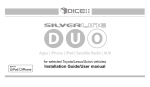
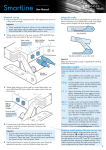
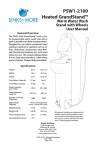
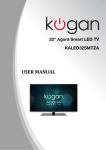
Coax A/V Agile Demodulator Tuner
W/IR Remote Control
User Manual
(Model: RFDM2‐PDK)
RFDM2-PDK Demodulator with IR Remote
1. Product Features:
This coax to composite A/V demodulator is a professional grade PAL D/K TV
channel converter, designed to work with coax TV signals such as cable TV or
satellite channels, closed circuit private TV channels or other RF modulated
signals to standard video/audio in composite RCA formats for various
applications such as displaying, recording, or further A/V broadcast and
distribution.
Easy 1-Minute setup. Simply connect the coax cable from your source to the coax input
of this converter and then use regular composite A/V cable to connect from the standard
video /audio output of this coax converter in RCA type to a TV display. No initial
configuration setup needed. No TV channel scan needed.
The operation of this coax video audio converter is 100% hardware operation. Easy cable
setup and no compatibility issues.
This coax cable signal agile demodulator can also be used a stand alone TV tuner. Featured
with support of full TV channel frequencies and the micro processor inside the unit can
decode all standard UHF/VHF TV, CATV and
satellite channels.
This external TV tuner can be fully operated and
controlled via the supplied IR remote controller or the
manual push buttons on the front panel of the unit,
just like the way you were using the TV remote to flip
between channels, mute the TV sound or up the
volume.
This unit is compact in size and it is rack mountable if
needed for large-scale broadcast TV system or
surveillance camera CCTV setup. Multiple units can
be daisy chained together on 19" rack using the optional rackmount kits. Rackmount kits are
sold separately.
1
2. Introduction :
Front Panel
1. IR: IR remote sensor/receiver
2. MUTE: Shut off the audio channel
3. SIGNAL: The LED lit on for indication
of unit engaging in channel switching.
5.
6.
7.
8.
AUDIO ▼: Volume down (level:16-0)
AUDIO ▲: Volume Up(level:0-16)
CHANNEL▼: Channel down
CHANNEL▲: Channel up
4. CHANNEL: LED screen for displaying
the current TV channel number
selected.
Rear Panel
1.
2.
3.
4.
Power IN: DC 7.5 ~ 12V 300mA
Power OUT: Power Loop-Through
VIDEO OUT: Composite Video output
AUDIO L-OUT: Stereo left audio out
2
5.
6.
7.
AUDIO R-OUT: Stereo right audio out
Terminal Block: Optional use for RS485
RF IN: RF coax input
3. Installation :
(1) RF Signal Input
(2) Video Output to Monitor
(3) Audio Output to speaker
(4) DC 7.5 ~ 12V 300mA Power Supply
4. LED Channel Display :
CH 100- CH 139
For higher TV channel number in 100+ (3 digit
display), the channel LED screen will display with a
“dot” between the 2 digits displayed on the panel.
The “dot” represents the base of 100. So if you see
“2.3” on the Channel LED screen, it actually means
Ch123 ( 100 + 23).
For example :
LED Display
Description
CH 13
CH 113
3
5. Remote Controller Panel :
1. Lock:
Lock/Unlock specific channel
(work with
)
2. Channel Up/Down:
CH+ : Fast switching channels up
CH - : Fast switching channels down
3. Volume Up/Down:
VOL+ : Volume up
VOL - : Volume down
4. Volume: Volume level display
5. CH ▲: TV channel up
6. CH ▼: TV channel down
▲ : TV volume down ( Volume level
7. VOL
range : 16 ~ 0 )
▼ : TV Volume up
8. VOL
9. RECALL: Return to the previous TV
channel selected
10. Mute: Mute the TV sound
11. Cancel: For re-entry
12. 100+: Set for higher channel number 100+
13. Numerical Key Pad: For manually entering
TV channel number
14. Channel Delete: Select specific TV
channel to be skipped/hidden
4
6. Remote Controller :
(1) After installation, you can switch channel by remote controller.
(2) For CH 02 ~ CH99, please enter 2 numbers.
ex. : CH 03 Î press 0 and 3
CH 30 Î press 3 and 0
when you switch channel, the “signal” light is on.
(3) For CH 100 or more, please press
ex. : CH 100 Î press
100+
LED Display
100+
button then 2 numbers.
+0+0
Description
CH 100
ex. : CH 110 Î press
100+
LED Display
+1+0
Description
CH 110
7. Channel Add / Delete ( only by remote control ) :
(1) Press
, you will see channel number start flashing.
LED Display
Description
Flashing channel number means that it is in
setting mode.
(2) Tune to the channel number that needs to be skipped/hidden from
other users:
With CH▲ , CH▼ or using numerical keys from the remote
controller.
5
(3) Press
button from the remote controller to lock and confirm.
LED Display
Description
no “dot”, this channel is deleted
If you want the hidden channel back, just press
again. You can see a “ dot “ there.
(4) Press
, setting is completed.
6
VHF/UHF Setup
The default setting for our RFDM2 is for CATV channel range. To reset RFDM2 unit for
VHF/UHF air TV channels. Please follow the steps below:
1. Power on the RFDM2 unit first. The LED screen on the front will display the system
status in “nC” or “nA”. The factory default of each RFDM2 is set for “nC”.
nC : standing for CABLE cannel system
nA : standing for AIR channel system
2. Press and hold the CHANNEL Down button for 10 seconds (do not release the
button). Wait until the LED digit screen starts to flash, then release the button.
3. Once the LED screen starts to flash, RFDM2 unit will display “01” flashing
alternatively, which means that the unit is ready for new setup.
At this time please press the CHANNEL Down or CHANNEL UP button from the front
panel to adjust change the value on the LED screen. There will be only two, “01” and
“02”.
01 for “nC” >>>>>>>>>>>> CABLE TV System
02 for “nA” >>>>>>>>>>>> VHF/UHF, Air TV Channels for analog antenna
4. After the adjustment, press and hold the CHANNEL Down button for 10 seconds or
wait until the LED digits stops flashing, then release the button.
5. Power off the RFDM2 unit and plug the power supply back on again to confirm if the
new setting is effective and displaying “nA” for the new system status.
7
Specification
Channel Display
Channel
Digital LED Channel Display
CATV - PAL D/K system (Ch1 to Ch100)
Frequency Range
48.25 - 869.75MHz
Input Level Range
-5 ~ +30 dbmv
Video Output Level 1Vp-p ± 0.2Vp-p (75 ohm)
RF Input : “ F “ type, Female
Composite Video Output : RCA Jack
Connector
Stereo Audio L-Output : RCA Jack
Stereo Audio R-Output : RCA Jack
DC Power IN / OUT : DC Jack
Noise Figure
10 dB maximum
Dimensions (WxHxD) 117 x 31 x 143
(unit:mm)
Power Consumption 1.5 watts
Temperature Range 0℃~40℃
Power Requirements AC 220-240V, DC7.5 ~ 12V / 300mA
8