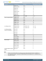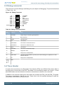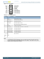
1
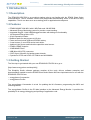
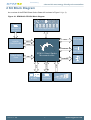
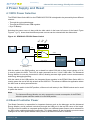
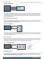
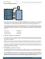
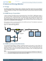
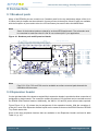
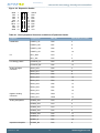
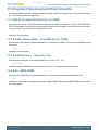
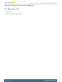
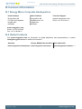
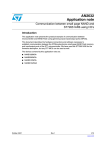
Preliminary
...the world's most energy friendly microcontrollers
USER MANUAL
Starter Kit EFM32GG-STK3700
The EFM32 Giant Gecko Starter Kit is a feature rich platform for evaluation,
prototyping and application development for the EFM32 Giant Gecko MCU family
with the ARM Cortex-M3 CPU core.
Main features:
• Advanced Energy Monitoring provides real-time information about the energy
consumption of an application or prototype design.
• On-board debugger with the possiblity to debug external targets.
• Several sensors, a 160-segment LCD Display, backup domain capacitor and an
on-board NAND Flash.
Preliminary
...the world's most energy friendly microcontrollers
1 Introduction
1.1 Description
The EFM32GG-STK3700 is an excellent starting point to get familiar with the EFM32 Giant Gecko
microcontrollers. The kit contains sensors and peripherals demonstrating some of the MCU's many
capabilities. The kit can also serve as a starting point for application development.
1.2 Features
•
•
•
•
•
•
•
•
•
•
•
•
•
•
EFM32GG990F1024 MCU with 1 MB Flash and 128 KB RAM.
Advanced Energy Monitoring system for precise current tracking.
Integrated Segger J-Link USB debugger/emulator with debug out functionality.
160 segment Energy Micro LCD.
20 pin expansion header.
Breakout pads for easy access to I/O pins.
Power sources include USB and CR2032 battery.
2 user buttons, 2 user LEDs and a touch slider.
Ambient Light Sensor and Inductive-capacitive metal sensor.
EFM32 OPAMP footprint.
32 MB NAND Flash.
USB Micro-AB (OTG) connector.
0.03F Super Capacitor for backup power domain.
Crystals for LFXO and HFXO: 32.768kHz and 48.000MHz.
1.3 Getting Started
The first step to get started with your new EFM32GG-STK3700 is to go to
[http://www.energymicro.com/simplicity]
The Simplicity Studio software package contains all the tools, drivers, software examples and
documentation needed to use the EFM32 Giant Gecko Starter Kit Some important tools for use with the
EFM32GG-STK3700 are:
• energyAware Commander
• energyAware Profiler
The energyAware Commander is a tool for updating the kit's firmware, programming the MCU and
launching demos.
The energyAware Profiler is the PC-side interface to the Advanced Energy Monitor. It provides the
possibility to do energy-debugging and profiling of application code.
2012-05-15 - TBD
2
www.energymicro.com
Preliminary
...the world's most energy friendly microcontrollers
2 Kit Block Diagram
An overview of the EFM32 Giant Gecko Starter Kit is shown in Figure 2.1 (p. 3)
Figure 2.1. EFM32GG-STK3700 Block Diagram
USB Mini-B
Connect or
8x20 Segm ent LCD
GPIO
BOARD
CONTROLLER
DEBUG
EXP Header
UART
LESENSE
Light Sensor
32Mx8 NAND
Flash
EFM32 Giant Gecko
Microcont roller
EBI
LESENSE
User But t ons
& LEDs
2012-05-15 - TBD
USB OTG
Connect or
3
ACMP
GPIO
Device/Host
LC Sensor
Touch Slider
www.energymicro.com
Preliminary
...the world's most energy friendly microcontrollers
3 Kit Hardware Layout
The layout of the EFM32 Giant Gecko Starter Kit is shown below.
Figure 3.1. EFM32GG-STK3700 hardware layout
8x20 Segm ent
LCD
32MB NAND
Flash
BU Capacit or
Am bient
Light Sensor
Debug
Header
USB
Int erface
EFM32 Reset
Expansion
Header
CR2032
Bat t ery
User Push-but t ons
LC Sensor
Power Source
Select
User LEDs
2012-05-15 - TBD
EFM32
USB
EFM32 Giant
Gecko MCU
4
Touch
Slider
EFM32 Debug
www.energymicro.com
Preliminary
...the world's most energy friendly microcontrollers
4 Power Supply and Reset
4.1 MCU Power Selection
The EFM32 Giant Gecko MCU on the EFM32GG-STK3700 is designed to be powered by three different
sources:
• Through the on-board debugger.
• Through the EFM32's own USB regulator.
• By a 3V Battery.
Selecting the power source is done with the slide switch in the lower left corner of the board. Figure
Figure 4.1 (p. 5) shows how the different power sources can be selected with the slide switch.
5V
USB Mini-B
Connect or
Advanced
Energy
Monit or
BG
D
SB
U
BA
T
Figure 4.1. EFM32GG-STK3700 Power Switch
3.3V
DBG
VMCU
USB
BAT
USB_VREGO
(3.3V)
EFM32 Giant
Gecko MCU
USB_VREGI
(5V)
USB OTG
Connect or
3V Lit hium Bat t ery
(CR2032)
With the switch in the DBG position, an on-board low noise LDO with a fixed output voltage of 3.3V
is used to power the MCU. This LDO is again powered from the "J-Link" USB cable. The Advanced
Energy Monitor is now also connected in series, allowing accurate high speed current measurements
and energy debugging/profiling.
With the switch in the USB position, the integrated linear regulator in the EFM32 Giant Gecko MCU is
used to power the rest of the chip as well as the USB PHY. This allows a USB device application where
the MCU acts as a bus powered device.
Finally, with the switch in the BAT position, a 20mm coin cell battery in the CR2032 socket can be used
to power the device.
Note
The Advanced Energy Monitor can only measure the current consumption of the EFM32
when the power selection switch is in the DBG position.
4.2 Board Controller Power
The Board Controller is responsible for important features such as the debugger and the Advanced
Energy Monitor, and is powered exclusively through the USB port in the top left corner of the board.
This part of the kit resides on a separate power domain, so a different power source can be selected for
the MCU while retaining debugging functionality. This power domain is also isolated to prevent current
leakage from the MCU power domain when power to the Board Controller is removed.
2012-05-15 - TBD
5
www.energymicro.com
Preliminary
...the world's most energy friendly microcontrollers
4.3 Backup Power Domain
The kit contains a backup capacitor that can be used together with the EFM32 Giant Gecko's backup
power domain. In this case, all other power sources are removed from the kit, and only a small part of
the EFM32 runs off the capacitor. It is also possible to enter backup mode while the Board Controller is
powered by selecting either BAT or USB with no battery in the socket or USB cable in the connector.
4.4 MCU Reset
The EFM32 MCU can be reset by a few different sources:
• The RESET button.
• The on-board debugger.
• An external debugger by pulling the #RST pin low.
4.5 Board Controller Reset
The Board Controller can be reset by removing and re-inserting the J-Link USB cable. Removing the
Board Controller USB cable will not reset the EFM32, but whenever the Board Controller is powered up
again, it will issue a RESET to the EFM32 through the on-board debugger.
2012-05-15 - TBD
6
www.energymicro.com
Preliminary
...the world's most energy friendly microcontrollers
5 Peripherals
The starter kit has a set of peripherals that showcase some of the features of the EFM32 Giant Gecko
microcontroller.
Be aware that most EFM32 I/O routed to peripherals are also routed to the breakout pads. This must be
taken into consideration when using the breakout pads for your application.
5.1 Push Buttons and LEDs
The kit has two user push buttons marked PB0 and PB1. They are connected to the EFM32, and are
debounced by RC filters with a time constant of 1ms. The buttons are connected to pins PB9 and PB10.
In addition to the two push buttons, the kit also features two yellow LEDs marked LED0 and LED1, that
are controlled by GPIO pins on the EFM32. The LEDs are connected to pins PE2 and PE3 in an activehigh configuration.
Figure 5.1. Buttons/LEDs
PE2
PE3
PB9
PB10
UIF_LED0
UIF_LED1
UIF_PB0
UIF_PB1
User But t ons
& LEDs
EFM32 MCU
5.2 LCD
A 28-pin Energy Micro LCD display is connected to the EFM32. The LCD has 8 common lines and 20
segment lines, giving a total of 160 segments in 8-plexed mode. These lines are not shared on the
breakout pads.
Figure 5.2. 160 Segment LCD
PA[ 11..7] LCD_SEG[ 39..35]
PB[ 2..0] LCD_SEG[ 34..32]
PD[ 12..9] LCD_SEG[ 31..28]
PA[ 6..0] , PA15 LCD_SEG[ 19..12]
8x20 Segm ent LCD
PB[ 6..3] LCD_COM[ 7..4]
PE[ 7..4] LCD_COM[ 3..0]
EFM32 MCU
Capacitors for the EFM32 Giant Gecko LCD boost function are also available on the EFM32GGSTK3700.
5.3 Capacitive Touch Slider
A touch slider utilizing the capacitive touch capability is available. It is placed beneath the two push
buttons on the kit. The slider interpolates 4 separate pads to find the exact position of a finger. For low
power operation, the touch slider can be used together with LESENSE to continuously scan all 4 pads,
using LESENSE channels 8 to 11.
2012-05-15 - TBD
7
www.energymicro.com
Preliminary
...the world's most energy friendly microcontrollers
Figure 5.3. Touch Slider
PC8 (ACMP1_CH0)
PC9 (ACMP1_CH1)
PC10 (ACMP1_CH2)
PC11 (ACMP1_CH3)
UIF_TOUCH0
UIF_TOUCH1
UIF_TOUCH2
UIF_TOUCH3
Touch Slider
EFM32 MCU
The capacitive touch slider works by sensing changes in the capacitance of the pads when touched by a
human finger. Sensing the changes in capacitance is done by setting up the touch pad as part of an RC
relaxation oscillator using the EFM32's analog comparator, and then counting the number of oscillations
during a fixed period of time.
5.4 Ambient Light Sensor
The kit has a light sensitive, transistor type, ambient light sensor connected to the low energy sensor
interface of the EFM32 Giant Gecko MCU. The sensor is placed above the push buttons and can be
used to sense changes in ambient light levels.
Figure 5.4. Light Sensor
LIGHT_EXCITE
PD6 (LES_ALTEX0)
PC6 (ACMP0_CH6)
LIGHT_SENSE
TEMT6200FX01
22K
EFM32 MCU
Two pins are used for the light sensor operation: one for excitation, and one for sensing. The sense pin
is connected to ACMP0 CH6. Both the excitation pin and the sense pin can be controlled directly from
the EFM32's LESENSE module.
5.5 LC Sensor
In the bottom right corner there is an inductive-capacitive sensor for demonstrating the low energy sensor
interface. By setting up oscillating currents in the inductor, metal nearby the inductor can be sensed by
measuring the oscillation decay time. The effective range is a few millimeters.
Figure 5.5. LC Metal Sensor
DAC_LC_EXCITE
100 nF
PC7 (ACMP0_CH7)
LES_LC_SENSE
390 uH
330 pF
PB12 (DAC0_OUT1)
1.5K
EFM32 MCU
Met al Object
5.6 NAND Flash
A 32MB NAND Flash is connected to the external bus interface of the EFM32 Giant Gecko MCU. The
interface is a simple 8-bit parallel interface. This peripheral demonstrates the EFM32 Giant Gecko's EBI
module's NAND support with built in ECC generation.
2012-05-15 - TBD
8
www.energymicro.com
Preliminary
...the world's most energy friendly microcontrollers
Figure 5.6. NAND Flash Interface
VMCU
PB15
NAND_PWR_EN
PE[ 15..8] EBI_AD[ 7..0]
I/O[ 7..0]
PC1
EBI_A24
ALE
PC2
EBI_A25
CLE
PF8
EBI_WE#
WE#
PF9
EBI_RE#
RE#
PD13
NAND_WP#
WP#
PD14
NAND_CE#
CE#
PD15
NAND_R/B#
R/B#
EFM32 MCU
NAND256W3A
A separate power switch is used to enable/disable the NAND flash, thus avoiding excess current draw
when not used. When NAND_PWR_EN is high, the NAND flash is powered from the same supply as
the EFM32 MCU. It is recommended to keep the write-protect line low during power transitions.
The ALE (address latch enable) and CLE (command latch enable) pins of the NAND Flash are connected
to the EBI Address pins 24 and 25, and the CE (chip enable) line is connected to a general GPIO pin.
This causes the NAND data, address and command registers to be mapped in the EFM32's address
space as:
Data register:
0x80000000
Address register:
0x81000000
Command register:
0x82000000
5.7 Backup Domain Capacitor
A small super capacitor is provided to evaluate the EFM32 Giant Gecko MCU's backup power domain.
The capacitor has a nominal value of 33 mF, and is connected with a 100 ohm series resistor to the
BU_VIN pin of the EFM32.
Because of the extremely low power consumption of the EFM32 in backup mode (400nA), the capacitor
can power a clock application using the low frequency crystal oscillator (LFXO) for more than 8 hours.
The series resistor allows measuring of the current drawn from the capacitor into the EFM32 device, by
simply using a multimeter to measure the voltage across it. Please refer to the schematic and assembly
drawings to locate the series resistor.
5.8 USB Micro-AB Connector
The EFM32GG-STK3700 board is equipped with a USB Micro-AB connector supporting USB Device
and Embedded Host modes. The figure below shows how the USB lines are connected to the EFM32.
The USB_VBUSEN line is connected to a current limited switch which supplies the VBUS line with 5V
when operating as a USB Host. The current limited switch also has a flag signal connected to the EFM32
which can notify it in case excessive current is drawn by the attached device. Note that the "J-Link" USB
cable must be inserted to provide 5V to the device when operating the EFM32 in host mode.
2012-05-15 - TBD
9
www.energymicro.com
Preliminary
...the world's most energy friendly microcontrollers
Figure 5.7. EFM32 USB Connector
5V
PF6 (GPIO)
PF5 (USB_VBUSEN)
Overcurrent
VBUS Enable
ID
PF12 (USB_ID)
D-
PF10 (USB_DM)
D+
PF11 (USB_DP)
VBUS
USB_VBUS
USB OTG
Connect or
USB_VREGI
USB_VREGO
1uF
4.7uF
5.9 Op-Amp Footprint
If the kit is flipped over there is a silk-print model of a typical operational amplifier feedback circuit. The
actual operational amplifier is one of the op-amps inside the EFM32. By soldering 0603 sized resistors
the EFM32 internal operational amplifier can be evaluated with exact resistor values.
2012-05-15 - TBD
10
www.energymicro.com
Preliminary
...the world's most energy friendly microcontrollers
6 Advanced Energy Monitor
6.1 Usage
The AEM (Advanced Energy Monitor) data is collected by the board controller and can be displayed
by the energyAware Profiler, available through Simplicity Studio. By using the energyAware Profiler,
current consumption and voltage can be measured and linked to the actual code running on the EFM32
in realtime.
6.2 AEM theory of operation
In order to be able to accurately measure current ranging from 0.1uA to 50mA (114dB dynamic range), a
current sense amplifier is utilized together with a dual gain stage. The current sense amplifier measures
the voltage drop over a small series resistor, and the gain stage further amplifies this voltage with two
different gain settings to obtain two current ranges. The transition between these two ranges occurs
around 250uA. Digital filtering and averaging is done within the Board Controller before the samples are
exported to the energyAware Profiler application.
During startup of the kit, an automatic calibration of the AEM is performed. This calibration compensates
for the offset error in the sense amplifiers.
Figure 6.1. Advanced Energy Monitor
5V
LDO
3.3V
VMCU
4.7R
Sense Resist or
Power Select
Swit ch
Current Sense
Am plifier
EFM32
Sensors &
Peripherals
HG
Dual Gain
St age
AEM
Processing
LG
6.3 AEM accuracy and performance
The Advanced Energy Monitor is capable of measuring currents in the range of 0.1uA to 50mA. For
currents above 250uA, the AEM is accurate within 0.1mA. When measuring currents below 250uA, the
accuracy increases to 1uA. Even though the absolute accuracy is 1uA in the sub 250uA range, the
AEM is able to detect changes in the current consumption as small as 100nA. The AEM produces 6250
current samples per second.
Note
The current measurement will only be correct when powering the EFM32 from USB power
through the debugger (power select switch set to "DBG").
2012-05-15 - TBD
11
www.energymicro.com
Preliminary
...the world's most energy friendly microcontrollers
7 Board Controller
The kit contains a board controller that is responsible for performing various board level tasks, such
as handling the debugger and the Advanced Energy Monitor. An interface is provided between the
EFM32 and the board controller in the form of a UART connection. The connection is enabled by setting
the EFM_BC_EN (PF7) line high, and using the lines EFM_BC_TX (PE0) and EFM_BC_RX (PE1) for
communicating.
Specific library functions has been provided in the kit Board Support Package that supports various
requests to be made to the board controller, such as quering AEM voltage or current. To use these
functions, the Board Support Package must be installed. See the Chapter 8 (p. 13) to find out more.
Note
The board controller is only available when USB power is connected.
2012-05-15 - TBD
12
www.energymicro.com
Preliminary
...the world's most energy friendly microcontrollers
8 Board Support Package
The Board Support Package (BSP) is a set of C source and header files that enables easy access to,
and control over some board specific features.
Compared to the Energy Micro development kit, the functionality is limited. Unless you need/want some
of the functions contained in the BSP, there is really no need to include or use it. The EFM32 in the Starter
Kit is fully usable without BSP support, and you can use all peripherals in the emlib without the BSP.
The BSP use EFM32 peripheral UART0, Location 1 (TX pin PE0, RX pin PE1) on baudrate 115200-8N-1 to communicate with the board controller.
Note
The BSP is only functional when the Starter Kit is USB-powered, using these function calls
with USB disconnected will give unpredictable results.
8.1 Installation location
When installing Simplicity Studio, the BSP will be installed in the user directory, typically in a location
such as
Win7: C:\Users\[username]\AppData\Roaming\energymicro\kits\EFM32GG_STK3700\
or something similar (depending on your OS/Windows version). All files in the board support package
are prefixed by stk.
8.2 Application Programming Interface
To use the BSP, include the Starter Kit header file, like this:
#include "stk.h"
All functions in the BSP are prefixed with STK_. The main initialization routine is defined as
void STK_Init(void);
and must be called before any access to the STK-functions. This function call will setup the UART
communication channel with a 115800 baud rate. This baud rate depends on the current core clock, so
correct clock configuration should be set before calling this function.
bool STK_Ready(void)
Returns true if the board controller is responding. A non-responding board will either return false, or
hang (i.e. if the EFM32 is powered by the CR2032 battery cell).
float STK_Current(void);
Returns instant current usage in milliamperes.
float STK_Voltage(void);
Returns instant voltage (VMCU) reading in volt.
bool STK_EnergyMode(uint8_t em);
Informs the board controller about the Energy Mode (sleep mode) we are going into. This information
can be used by the board controller to present a richer visual graph for illustrating what the EFM32 is
currently doing.
2012-05-15 - TBD
13
www.energymicro.com
Preliminary
...the world's most energy friendly microcontrollers
In addition to these main functions, full documentation of the complete API is included in the Doxygen/
HTML documentation of the installed package.
8.3 Example Applications
Under the kits/EFM32GG_STK3700/examples folder in your installation directory, you will find an
example program using the BSP, with corresponding project/Makefiles for the supported IDEs.
The examples folder also contains examples showing how to use the different peripherals on the
EFM32GG-STK3700.
8.4 How to include in your own applications
The easiest way to include the BSP in your application is to base your work on the example application
that use the BSP. The following items are recommended for correct configuration:
1. Make sure you define the correct part number (i.e. EFM32GG990F1024) as a preprocessor defined
symbol
2. Make sure you define the correct part number (i.e. EFM32GG990F1024) for your project file
3. Add and include the EFM32_CMSIS-files (startup_efm32.s, system_efm32.c, core_cm3.c) to your
project
4. Add and include all BSP package .c-files, with the stk-prefix to your project
5. Configure include paths to point at the CMSIS/CM3/CoreSupport and CMSIS/CM3/DeviceSupport/
EnergyMicro/EFM32 directories
6. Configure include paths to point to the kits/EFM32GG_STK3700/bsp directory
Make sure you call "STK_Init()" early at startup, and you should be all set.
2012-05-15 - TBD
14
www.energymicro.com
Preliminary
...the world's most energy friendly microcontrollers
9 Connectors
9.1 Breakout pads
Many of the EFM32's pins are routed out to "breakout pads" at the top and bottom edges of the kit. A
2.54mm pitch pin header can be soldered in for easy access to these pins. Most I/O pins are available,
with the exception of pins used to drive the LCD and some pins used to drive the NAND flash.
Note
Some of the breakout pads are shared by on-board EFM peripherals. The schematic must
be consulted to make sure that it is OK to use a shared pin in your application.
Figure 9.1. Breakout pads and Expansion Header
3
3 VU
C
M 4
V D13
P 1
D
P D8
P 7
D
P 6
D
P D
N
G 5
D
P 4
D
P 3
D
P 2
D
P 1
D
P 0
D
P D
N
G 15
D
P 12
B
P 11
B
P ND
G B9
P 0
1
B
P 5V
Debug Connect or
Expansion Header
3 V3
5V
PD 6
PD 5
PD 4
PD 3
PD 2
PD 1
PD 0
V M CU
20
18
16
14
12
10
8
6
4
2
19
17
15
13
11
9
7
5
3
1
GN D
PC0
PC3
PC4
PC5
PB1 1
PB1 2
PD 7
PC6
GN D
O K
W L
S CO
W I
S D T#
W
S E
ES
R D
N
G
3U
3V C
M
V 9
F
P
F8
P D
N
G 7
C
P
2
C
P 1
C
P 0
C
P D
N
G 3
E
P 2
E
P 1
E
P 0
E
P D
N
G 14
A
P 13
A
P 12
A
P
5V
Debug Pins
Note
Pins PC3, PC4, PC5 and PC6 are also available as surface mounted pads beneath the
USB Micro-AB connector
9.2 Expansion header
On the right hand side of the board an angled 20 pin expansion header is provided to allow connection of
peripherals or plugin boards. The connecter contains a number of I/O pins that can be used with most of
the EFM32 Giant Gecko's features. Additionally, the VMCU, 3V3 and 5V power rails are also exported.
Figure Figure 9.1 (p. 15) shows the pin assignment of the expansion header. With the exception of
a few pins, most of the Expansion Header's pins are the same as those on the EFM32 Gecko or EFM32
Tiny Gecko starter kits.
Some of the chip peripheral functions that are available on the Expansion Header are listed in table
Table 9.1 (p. 16) .
2012-05-15 - TBD
15
www.energymicro.com
Preliminary
...the world's most energy friendly microcontrollers
Figure 9.2. Expansion Header
GND
PC0
PC3
PC4
PC5
PB11
PB12
PD7
PC6
GND
1
3
5
7
9
11
13
15
17
19
2
4
6
8
10
12
14
16
18
20
VMCU
PD0
PD1
PD2
PD3
PD4
PD5
PD6
5V
3V3
Table 9.1. Some peripheral functions available on Expansion Header
Peripheral
Peripheral pin
MCU Pin
EXP Header pin number
USART/SPI
USART1_TX
PD0
4
USART1_RX
PD1
6
USART1_CLK
PD2
8
USART1_CS
PD3
10
I2C1_SDA
PC4
7
I2C1_SCL
PC5
9
LEUART0_TX
PD4
12
LEUART0_RX
PD5
14
ADC0_CH0
PD0
4
ADC0_CH1
PD1
6
ADC0_CH2
PD2
8
ADC0_CH3
PD3
10
ADC0_CH4
PD4
12
ADC0_CH5
PD5
14
ADC0_CH6
PD6
16
ADC0_CH7
PD7
15
Digital to Analog
Converter
DAC0_CH0
PB11
11
DAC0_CH1
PB12
13
Analog Comparator
ACMP0_CH0
PC0
3
ACMP0_CH3
PC3
5
ACMP0_CH4
PC4
7
ACMP0_CH5
PC5
9
ACMP0_CH6
PC6
17
ACMP0_O
PD6
16
ACMP1_O
PD7
15
OPAMP_N0
PC5
9
I²C
Low Energy UART
Analog to Digital
Converter
Operational Amplifier
2012-05-15 - TBD
16
www.energymicro.com
Preliminary
...the world's most energy friendly microcontrollers
Peripheral
Timer Compare/Capture
Low Energy Timer
Low Energy Sensor
Interface (LESENSE)
Pulse Counter
Peripheral Reflex System
(PRS)
Peripheral pin
MCU Pin
EXP Header pin number
OPAMP_P0
PC4
7
OPAMP_OUT0
PB11
11
OPAMP_N1
PD7
15
OPAMP_P1
PD6
16
OPAMP_OUT1
PB12
13
OPAMP_N2
PD3
10
OPAMP_P2
PD4
12
OPAMP_OUT2
PD5, PD0
14, 4
TIMER0_CC0
PD1
6
TIMER0_CC1
PD2
8
TIMER0_CC2
PD3
10
TIMER1_CC0
PD6
16
TIMER1_CC1
PD7
15
TIMER1_CC2
PB11
11
LETIM0_OUT0
PD6, PB11, PC4
16, 11, 7
LETIM0_OUT1
PD7, PB12, PC5
15, 13, 9
LES_CH0
PC0
3
LES_CH3
PC3
5
LES_CH4
PC4
7
LES_CH5
PC5
9
LES_CH6
PC6
17
LES_ALTEX0
PD6
16
LES_ALTEX1
PD7
15
PCNT0_S0IN
PD6
16
PCNT0_S1IN
PD7
15
PCNT1_S0IN
PC4
7
PCNT1_S1IN
PC5
9
PCNT2_S0IN
PD0
4
PCNT2_S1IN
PD1
6
PRS_CH2
PC0
3
Note
Please note that this table only sums up some of the alternate functions available on
the expansion header. Consult the EFM32GG990F1024 datasheet for a complete list of
alternate functions.
2012-05-15 - TBD
17
www.energymicro.com
Preliminary
...the world's most energy friendly microcontrollers
9.3 Debug connector
This connector is used for Debug In and Debug Out (see chapter on Debugging). The pinout is described
in Table 9.2 (p. 18) .
Figure 9.3. Debug Connector
NC 2
GND 4
GND 6
GND 8
GND 10
GND 12
GND 14
GND 16
Cable Det ect 18
GND 20
1
3
5
7
9
11
13
15
17
19
VTARGET
# TRST
TDI
TMS/SWDIO
TCK/SWCLK
RTCK
TDO/SWO
# RESET
PD
PD
Table 9.2. Debug connector pinout
Pin
number
Function
Note
1
VTARGET
Target voltage on the debugged application.
2
NC
Not Connected
3
#TRST
JTAG tap reset
5
TDI
JTAG data in
7
TMS/SWDIO
JTAG TMS or Serial Wire data I/O
9
TCK/SWCLK
JTAG TCK or Serial Wire clock
11
RTCK
JTAG RTCK
13
TDO/SWO
JTAG TDO or Serial Wire Output
15
#RESET
Target MCU reset
17
PD
This pin has a 100k pulldown.
18
Cable detect
This signal must be pulled to ground by the external debugger or application for cable
insertion detection.
19
PD
This pin has a 100k pulldown.
4, 6, 8,
10, 12,
14, 16,
20
GND
9.4 Trace Header
A header with connections to the Embedded Trace Module (ETM) in the EFM32 Giant Gecko MCU is
provided on the reverse side of the PCB. The header is not mounted by default, but a 20-pin, 1.27mm
pitch SMD header can be soldered on to allow an external trace emulator to be connected.
In addition to the serial wire debug pins, this header also contains the ETM_CLK and ETM_TD signals.
The pinout is described in Table 9.3 (p. 19) . Please refer to the kit assembly drawing to locate the
trace header, which has the reference P200.
2012-05-15 - TBD
18
www.energymicro.com
Preliminary
...the world's most energy friendly microcontrollers
Figure 9.4. Trace Header
VTref
GND
GND
NC
GND
NC
NC
GND
GND
GND
1
3
5
7
9
11
13
15
17
19
2
4
6
8
10
12
14
16
18
20
SWDIO/TMS
SWCLK/TCK
SWO/TDO
TDI (NC)
nRESET
TRACECLK
TRACE-DATA[ 0]
TRACE-DATA[ 1]
TRACE-DATA[ 2]
TRACE-DATA[ 3]
Table 9.3. Trace header pinout
Pin
number
Function
Note
1
VTref
Target reference voltage.
2
SWDIO/TMS
Serial Wire Data Input/Output
4
SWCLK/TCK
Serial Wire Clock input
6
SWO/TDO
Serial Wire Output trace port
8
TDI
Not Connected on the EFM32GG-STK3700
10
nRESET
Target CPU reset signal.
12
TRACECLK
Trace clock output. Trace clock = 1/2 CPU clock.
14
TRACE-DATA[0]
Trace data output pin 0.
16
TRACE-DATA[1]
Trace data output pin 1.
18
TRACE-DATA[2]
Trace data output pin 2.
20
TRACE-DATA[3]
Trace data output pin 3.
7, 11, 13
NC
Not Connected
3, 5, 9,
15, 17,
19
GND
Note
The EFM32GG-STK3700 debugger does not contain any trace functionality apart from
the basic functionality provided with Serial Wire View (SWV). This header is only useful
together with an external trace emulator.
2012-05-15 - TBD
19
www.energymicro.com
Preliminary
...the world's most energy friendly microcontrollers
10 Debugging
The EFM32GG-STK3700 contains an integrated debugger, which can be used to download code and
debug the EFM32 Giant Gecko MCU. In addition to programming the microcontroller on the kit, the
debugger can also be used to program and debug external Energy Micro devices.
10.1 Debug Modes
Programming external devices is done by connecting to a target board through the provided debug
connector, and by setting the debug mode to OUT. The same connector can also be used to connect
an external emulator to the EFM32 MCU on the kit, by setting the debug mode to IN. A summary of the
different supported debug modes are described in Table 10.1 (p. 20) .
Table 10.1. Debug modes
Mode
Description
Debug MCU
In this mode the on-board debugger is connected to EFM32 on the EFM32GG-STK3700.
Debug IN
In this mode the on-board debugger is disconnected, and an external debugger can be connected to
debug the EFM32 on the EFM32GG-STK3700.
Debug OUT
In this mode the on-board debugger can be used to debug an EFM32 mounted in your own
application.
Selecting the active debug mode is done with a drop-down menu in the energyAware Commander tool,
which is available through Simplicity Studio.
10.2 Debugging during battery operation
When the EFM32 is powered by the battery and the USB is still connected, the on-board debug
functionality is available. If the USB power is disconnected the debug controller on the kit will not work.
To enable debugging in this mode, connect an external debugger (e.g. another EFM32GG-STK3700)
to the debug pads in the bottom right corner of the EFM32GG-STK3700. These pads are connected
directly to the EFM32 debug interface. The pinout of this debug connector is printed on the PCB, and
is also shown in the lower right corner of Figure 9.1 (p. 15)
2012-05-15 - TBD
20
www.energymicro.com
Preliminary
...the world's most energy friendly microcontrollers
11 Integrated Development Environments
The Energy Micro software packages contains various examples in source form to use with the Starter
Kit. The following IDEs are supported.
11.1 IAR Embedded Workbench for ARM
An evaluation version of IAR Embedded Workbench for ARM is included on a CD in the EFM32GGSTK3700 package. Check the quick start guide for where to find updates, and IAR's own documentation
on how to use it. You will find the IAR project file in the
iar
subfolder of each project
11.2 Rowley Associates - CrossWorks for ARM
See the quick start guide for download details for CrossWorks for ARM. You will find CrossWorks project
files in the
rowley
subfolder of each project.
11.3 CodeSourcery - Sourcery G++
See the quick start guide for download details for Sourcery G++. The
codesourcery
subfolder contains Makefiles for use with the Sourcery G++ development environment.
11.4 Keil - MDK-ARM
See the quick start guide for download details for evaluation versions of Keil MDK-ARM. The
arm
subfolder in each project contains project files for MDK-ARM. Please see the MDK-ARM documentation
for usage details.
2012-05-15 - TBD
21
www.energymicro.com
Preliminary
...the world's most energy friendly microcontrollers
12 energyAware Commander and Upgrades
The energyAware Commander is a program that comes with Simplicity Studio. It can perform various
kit and EFM32 specific tasks.
12.1 eA Commander Operation
This utility gives the ability to program the EFM32, upgrade the kit, lock and unlock devices and more.
Some of the features will only work with Energy Micro kits, while other will work with a J-Link debugger
connected. Press the "F1" button, or select the "Help->Help" menu item for a full description.
12.2 Upgrades
Upgrading the kit is done through Simplicity Studio. The Studio will automatically check for new updates
on startup.
You can also use the energyAware Commander for manual upgrades. Select the "Kit" icon, use the
"Browse" button to select the correct file ending in ".emz", and press the "Install package button".
2012-05-15 - TBD
22
www.energymicro.com
Preliminary
...the world's most energy friendly microcontrollers
13 Schematics, Assy Drawings and BOM
The schematics, assembly drawings and bill of materials (BOM) for the EFM32 Giant Gecko Starter Kit
board is available through Simplicity Studio when the kit documentation package has been installed.
2012-05-15 - TBD
23
www.energymicro.com
Preliminary
...the world's most energy friendly microcontrollers
14 Kit Revision History and Errata
14.1 Revision History
Table 14.1. Kit Revision History
Kit Revision
Released
Description
A02
26.04.2012
Initial production version
A03
15.05.2012
Updated PCB to add test-points for EFM32 USB.
14.2 Errata
Table 14.2. Kit Errata
Kit Revision
Problem
Description
A02
Footprint of C250 is
wrong.
One of the capacitors on the OPAMP footprint, as described in
Section 5.9 (p. 10) , is a 0402 sized footprint instead of 0603.
This is a minor problem, and might cause some difficulties when
trying to add a capacitor here. The error is only present on PCB's
marked "PCB2200 REV. A02".
2012-05-15 - TBD
24
www.energymicro.com
Preliminary
...the world's most energy friendly microcontrollers
15 Document Revision History
15.1 Revision 0.10
2012-05-15
First revision with revision history.
2012-05-15 - TBD
25
www.energymicro.com
Preliminary
...the world's most energy friendly microcontrollers
A Disclaimer and Trademarks
A.1 Disclaimer
Energy Micro AS intends to provide customers with the latest, accurate, and in-depth documentation
of all peripherals and modules available for system and software implementers using or intending to
use the Energy Micro products. Characterization data, available modules and peripherals, memory
sizes and memory addresses refer to each specific device, and "Typical" parameters provided can and
do vary in different applications. Application examples described herein are for illustrative purposes
only. Energy Micro reserves the right to make changes without further notice and limitation to product
information, specifications, and descriptions herein, and does not give warranties as to the accuracy
or completeness of the included information. Energy Micro shall have no liability for the consequences
of use of the information supplied herein. This document does not imply or express copyright licenses
granted hereunder to design or fabricate any integrated circuits. The products must not be used within
any Life Support System without the specific written consent of Energy Micro. A "Life Support System"
is any product or system intended to support or sustain life and/or health, which, if it fails, can be
reasonably expected to result in significant personal injury or death. Energy Micro products are generally
not intended for military applications. Energy Micro products shall under no circumstances be used in
weapons of mass destruction including (but not limited to) nuclear, biological or chemical weapons, or
missiles capable of delivering such weapons.
A.2 Trademark Information
Energy Micro, EFM32, EFR, logo and combinations thereof, and others are the registered trademarks or
trademarks of Energy Micro AS. ARM, CORTEX, THUMB are the registered trademarks of ARM Limited.
Other terms and product names may be trademarks of others.
2012-05-15 - TBD
26
www.energymicro.com
Preliminary
...the world's most energy friendly microcontrollers
B Contact Information
B.1 Energy Micro Corporate Headquarters
Postal Address
Visitor Address
Technical Support
Energy Micro AS
P.O. Box 4633 Nydalen
N-0405 Oslo
NORWAY
Energy Micro AS
Sandakerveien 118
N-0484 Oslo
NORWAY
support.energymicro.com
Phone: +47 40 10 03 01
www.energymicro.com
Phone: +47 23 00 98 00
Fax: + 47 23 00 98 01
B.2 Global Contacts
Visit www.energymicro.com for information on global distributors and representatives or contact
[email protected] for additional information.
Americas
Europe, Middle East and Africa Asia and Pacific
www.energymicro.com/americas www.energymicro.com/emea
2012-05-15 - TBD
27
www.energymicro.com/asia
www.energymicro.com
Preliminary
...the world's most energy friendly microcontrollers
Table of Contents
1. Introduction .............................................................................................................................................. 2
1.1. Description .................................................................................................................................... 2
1.2. Features ....................................................................................................................................... 2
1.3. Getting Started ............................................................................................................................... 2
2. Kit Block Diagram ..................................................................................................................................... 3
3. Kit Hardware Layout .................................................................................................................................. 4
4. Power Supply and Reset ............................................................................................................................ 5
4.1. MCU Power Selection ..................................................................................................................... 5
4.2. Board Controller Power .................................................................................................................... 5
4.3. Backup Power Domain .................................................................................................................... 6
4.4. MCU Reset ................................................................................................................................... 6
4.5. Board Controller Reset .................................................................................................................... 6
5. Peripherals ............................................................................................................................................... 7
5.1. Push Buttons and LEDs ................................................................................................................... 7
5.2. LCD ............................................................................................................................................. 7
5.3. Capacitive Touch Slider ................................................................................................................... 7
5.4. Ambient Light Sensor ...................................................................................................................... 8
5.5. LC Sensor ..................................................................................................................................... 8
5.6. NAND Flash .................................................................................................................................. 8
5.7. Backup Domain Capacitor ................................................................................................................ 9
5.8. USB Micro-AB Connector ................................................................................................................. 9
5.9. Op-Amp Footprint .......................................................................................................................... 10
6. Advanced Energy Monitor ......................................................................................................................... 11
6.1. Usage ......................................................................................................................................... 11
6.2. AEM theory of operation ................................................................................................................. 11
6.3. AEM accuracy and performance ...................................................................................................... 11
7. Board Controller ...................................................................................................................................... 12
8. Board Support Package ............................................................................................................................ 13
8.1. Installation location ........................................................................................................................ 13
8.2. Application Programming Interface ................................................................................................... 13
8.3. Example Applications ..................................................................................................................... 14
8.4. How to include in your own applications ............................................................................................ 14
9. Connectors ............................................................................................................................................. 15
9.1. Breakout pads .............................................................................................................................. 15
9.2. Expansion header ......................................................................................................................... 15
9.3. Debug connector ........................................................................................................................... 18
9.4. Trace Header ............................................................................................................................... 18
10. Debugging ............................................................................................................................................ 20
10.1. Debug Modes ............................................................................................................................. 20
10.2. Debugging during battery operation ................................................................................................ 20
11. Integrated Development Environments ....................................................................................................... 21
11.1. IAR Embedded Workbench for ARM ............................................................................................... 21
11.2. Rowley Associates - CrossWorks for ARM ....................................................................................... 21
11.3. CodeSourcery - Sourcery G++ ....................................................................................................... 21
11.4. Keil - MDK-ARM ......................................................................................................................... 21
12. energyAware Commander and Upgrades ................................................................................................... 22
12.1. eA Commander Operation ............................................................................................................. 22
12.2. Upgrades ................................................................................................................................... 22
13. Schematics, Assy Drawings and BOM ....................................................................................................... 23
14. Kit Revision History and Errata ................................................................................................................. 24
14.1. Revision History .......................................................................................................................... 24
14.2. Errata ........................................................................................................................................ 24
15. Document Revision History ...................................................................................................................... 25
15.1. Revision 0.10 .............................................................................................................................. 25
A. Disclaimer and Trademarks ....................................................................................................................... 26
A.1. Disclaimer ................................................................................................................................... 26
A.2. Trademark Information ................................................................................................................... 26
B. Contact Information ................................................................................................................................. 27
B.1. Energy Micro Corporate Headquarters .............................................................................................. 27
B.2. Global Contacts ............................................................................................................................ 27
2012-05-15 - TBD
28
www.energymicro.com
Preliminary
...the world's most energy friendly microcontrollers
List of Figures
2.1.
3.1.
4.1.
5.1.
5.2.
5.3.
5.4.
5.5.
5.6.
5.7.
6.1.
9.1.
9.2.
9.3.
9.4.
EFM32GG-STK3700 Block Diagram ........................................................................................................... 3
EFM32GG-STK3700 hardware layout ......................................................................................................... 4
EFM32GG-STK3700 Power Switch ............................................................................................................ 5
Buttons/LEDs ......................................................................................................................................... 7
160 Segment LCD .................................................................................................................................. 7
Touch Slider .......................................................................................................................................... 8
Light Sensor .......................................................................................................................................... 8
LC Metal Sensor .................................................................................................................................... 8
NAND Flash Interface .............................................................................................................................. 9
EFM32 USB Connector .......................................................................................................................... 10
Advanced Energy Monitor ....................................................................................................................... 11
Breakout pads and Expansion Header ...................................................................................................... 15
Expansion Header ................................................................................................................................. 16
Debug Connector .................................................................................................................................. 18
Trace Header ....................................................................................................................................... 19
2012-05-15 - TBD
29
www.energymicro.com
Preliminary
...the world's most energy friendly microcontrollers
List of Tables
9.1. Some peripheral functions available on Expansion Header ............................................................................
9.2. Debug connector pinout .........................................................................................................................
9.3. Trace header pinout ..............................................................................................................................
10.1. Debug modes .....................................................................................................................................
14.1. Kit Revision History .............................................................................................................................
14.2. Kit Errata ...........................................................................................................................................
2012-05-15 - TBD
30
16
18
19
20
24
24
www.energymicro.com