1
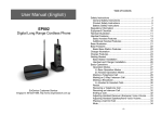
User’s Manual
For
The S³P.I. Learning System
v.0411
S3P.I. Learning System
Users Guide
TABLE OF CONTENTS
COMPONENTS
3
COMPONENTS INCLUDED
QUICK START GUIDE
4
QUICK START GUIDE
BATTERY CHARGING
5
5
CHARGING THE RADIOS
CHARGING THE VIDEO BATTERY PACKS
SETUP AND WEARING THE EQUIPMENT
BELT PACKS
GENERAL
BELTS
ANTENNA
POWER
6
6
6
6
RADIO
7
7
8
CONTROLS
CONTROL OPERATION – GENERAL
USING YOUR RADIOS &.EARSETS
GLASSES
ADJUSTMENTS
9
CAMERA (COACH GLASSES)
GENERAL
FRAMING/DISTANCE
ALIGNMENT
9
9
9-10
CONNECTIONS
POWER
ATHLETE PACK
COACH PACK
POWER BOTH PACKS
10
10
11
11
USING THE SYSTEM
SELECT ACTIVITY FOR IMPROVEMENT
PROVIDE VERBAL FEEDBACK
LIMIT INITIAL PRACTICE SESSIONS
INTRODUCE NEW ACTIVITIES AFTER SUCCESS ON PREVIOUS ACTIVITIES
12
12
12
12
TROUBLESHOOTING
GENERAL
POWER
CONNECTIONS
ALIGNMENT
CONTACT SUPPORT
13
13
13
13
13
WARRANTY
14
WARRANTY
SPECIFICATIONS
14
14
15
15
RADIO
VIDEO
BATTERY PACKS
CHARGERS
v.0411
M-Coast Enterprises LLC
www.m-coast.com
2
S3P.I. Learning System
Users Guide
Components Included
Case
Waterproof and dustproof with automatic
pressure purge system and molded-in padlock
holes.
Case Interior
Fully padded with compartments for all
components.
Belt Packs
Two double compartment ballistic nylon belt
packs with hook and loop closures.
Belt Packs – Interior
The two compartment packs carry the video and
audio equipment for the system.
Belts
Two belts are included with the system. Both
have quick clip adjustable buckles and the
athlete belt has integrated antennas.
Video Battery Chargers
Two intelligent chargers for the video
components in the packs.
Monitoring Glasses
One set for the athlete and one set with a video
camera for the coach.
Duplexing Radios
A master and a remote radio with
earset/microphone units and chargers for
each radio.
v.0411
M-Coast Enterprises LLC
www.m-coast.com
3
S3P.I. Learning System
Users Guide
Quick Start Guide
Step
Notes
Detail Section and Page
Charge all units
Charge the master and remote radios with
supplied chargers and batteries in the coach
and athlete belt packs.
Battery Charging
Radios – p. 5
Video – p. 5
Connect power
Connect power cable at bottom of switch box
on coach and athlete belt pack.
Setup & Wearing the
Equipment.
Connections
Power – p. 10
Clip on belt pack
Wear belts and belt packs outside of outer
clothing. Snap belt buckle halves together and
pull loose belt end until comfortably snug.
Setup & Wearing the
Equipment.
Belt Packs – p. 8
Attach earset
Loop elastic earset band over right ear. Built-in
microphone will automatically be placed near
your mouth.
Setup and Wearing the
Equipment
Using Your Radios
&.Earsets – p. 7
Slip on glasses
Adjust elastic sport band behind the head to
keep glasses comfortably in place while
practicing.
Setup & Wearing the
Equipment.
Glasses – p. 9
Connect cables
Insert plugs from earsets into jacks on radios
through access openings in belt packs. Insert
flat connectors from glasses into mating jacks
on video controllers. On coach pack, connect
camera power (red to red) and video (yellow to
yellow).
Setup & Wearing the
Equipment.
Connections
Power – p. 10
Athlete Pack – p. 10
Coach Pack – p. 11
Turn on pack
power switch
Toggle red rocker switches at top of belt pack
switch boxes until red pilot light is visible.
Connections
Power Both Packs – p. 11
Turn on video
controller power
switch
Through access opening in the front of belt
pack, press video controller power button until
green pilot light is visible.
Connections
Power Both Packs – p. 11
Adjust glasses
Adjust the image height with the nose pad and
left or right at the optical module. Adjust image
clarity with focus tab at top of optical module.
Setup & Wearing the
Equipment.
Glasses
Adjustment – p. 9
Adjust camera
If necessary, slightly loosen the knob on the
camera mount and turn or swivel the camera to
the desired view.
Setup & Wearing the
Equipment.
Camera (Coach Glasses)
Alignment – pp. 9&10
Turn on power to
radios.
Rotate on/off/volume knob clockwise to turn on
radios and adjust volume.
Setup & Wearing the
Equipment.
Using Your Radios &
Headsets - p. 7
v.0411
M-Coast Enterprises LLC
www.m-coast.com
4
S3P.I. Learning System
Users Guide
Battery Charging
Charging the Radios
First charging and after prolonged idle period:
The batteries that provide power to your system must be 'drained". Simply follow the
procedure below within 48 hours be-fore each use.
1. Turn ON all radios until LED lights turn OFF to drain battery power.
2. Turn power OFF to all radios.
3. Plug AC Charger/Adapter into a wall outlet and attach to radio charge socket.
4. Charge each radio for 10 - 12 hours.
5. The transceiver battery charges fully in 10 - 12 hours.
To prevent overheating of the charger and to prevent damage to the charge circuit do
not leave the charger plugged in for more than 24 hours. A fully charged battery will
operate in full duplex up to five hours.
Charging Video Battery Packs
Charge the video battery packs only with the supplied intelligent chargers. These
chargers are designed to sense and analyze the condition and balance of the battery
pack and then apply the correct charge. It is important to unplug the chargers from the
electrical outlet immediately before beginning the charging process and then plug
them in the outlet, again. This “resets” their memories and ensures that they will
correctly analyze the battery pack for charging. The battery packs are equipped with a
circuit board to protect them during normal use and charging.
Either charger can be used for the Coach or Athlete battery pack.
Charging is best done in a cool and dry place, out of direct sunlight.
Following steps apply to charging the Coach or Athlete battery pack. It is not
necessary to remove the video components or battery packs from the belt pack.
1. Turn off power rocker switch at top of power switch box fig. 1
2. Remove power cable plug from bottom power switch box. fig. 2
3. Disconnect intelligent charger power supply cable from electrical outlet for a
few seconds and then reconnect to outlet.
4. Connect charging cable from the intelligent charger to the power cable from the
belt pack. fig. 3
5. Note: red light on intelligent charger should now be visible indicating the
charging has begun.
6. Charging continues until the green light on the intelligent charger is visible.
Length of time needed for charging will depend on the degree of discharge at
the start of the process. Allow several hours for the charging cycle to be
completed.
Fully charged battery packs should allow video function for six to eight hours.
fig. 1
fig. 2
fig.3
v.0411
M-Coast Enterprises LLC
www.m-coast.com
5
S3P.I. Learning System
Users Guide
Setup and Wearing the Equipment
Belt Packs
General
Two belt packs are supplied with the system. Each one has double compartment for
the radio and video equipment and is clearly marked for Coach and Athlete. They
are made of ballistic nylon to protect the equipment and include a MOLLE (an
acronym for MOdular Lightweight Load-carrying Equipment, the current generation
of load-bearing equipment utilized by the United States armed forces) mounting
system to keep them securely fastened to the belt and wearer.
Both packs should be worn on the right side of the body as the cable for the
monitoring glasses is on the right side. The athlete pack is best worn just behind the
right hip to minimize interference with activity. The coach pack is best worn in front
of the right hip to provide the best possible video transmission. The video signal is
transmitted from the front of the coach pack so; keeping the pack directed at the
athlete will produce the best video signal.
Belts
A belt is supplied for each of the belt packs and both are fitted with a quick snap
buckle. The belts and belt packs should be worn on the outside of outerwear for
access and to achieve clear video signal. Although the standard belt is identified as
a 28” to 34”, it is actually much longer to accommodate use over outerwear. The
identified size relates to the placement of the antennas on the Athlete belt.
The standard Coach belt is longer and will cover up to 44”. It has no antennas.
Antenna
The belt supplied with the athlete pack is fitted with antennas to provide the best
possible video reception during the dynamic use of the system. When worn
properly, they allow ‘line of sight’ (an unobstructed path between sending and
receiving antennas) reception between the coach and athlete pack even as the
athlete changes directions or positions. A connector is
located between the belt and belt pack (fig. 6) and
generally protected by the belt and pack. Care must be
taken to avoid forcibly sliding the pack along the belt to
avoid damaging the antenna connection. This
connection only requires attention when changing from
the standard to large athlete belt.
fig. 6
Power
Each of the belt packs is equipped with a battery pack capable of powering the
video equipment for six to eight hours. The power cable, from the batteries, is
connected by an easy to use connector plug, to a switch box between the two pack
compartments (figs.1&2-p.5). This power cable is used for both powering the video
system and, when disconnected, recharging the battery pack (see section Charging
the Video Batteries). The switch box is equipped with a rocker switch, at the top
(fig.1-p.5). When the switch light is visible, power is available to all of the video
components in that pack. Toggling the rocker switch to the off position extinguishes
the light in the switch and removes power from all of the video components in that
pack. The units should be in the off position whenever they are not in use.
v.0411
M-Coast Enterprises LLC
www.m-coast.com
6
S3P.I. Learning System
Users Guide
Setup and Wearing the Equipment
Radio
Controls
1
2
3
4&5
6
7
8
9
10
11
On/Off, Volume knob
Talk button - up=standby; down=talk mode
Channel selectivity button - up=channel A; down=channel B.
Channel and status indicators A and B; startup mode=green; standby
mode=red; communication mode=orange
Battery low /charge indicator
Antenna
Headset socket
Belt clip
Charger socket
Channel dip switch inside battery compartment (do not alter settings)
Control Operation - General
1. Begin with radios in OFF position.
2. Turn radios ON by rotating on/off/volume knob clockwise.
3. Using CHANNEL button, select the operating frequencies indicated by green
light (A or B). Both the master and remote radio MUST be on the same
channel.
4. Set TALK button on each radio to STANDBY.
v.0411
M-Coast Enterprises LLC
www.m-coast.com
7
S3P.I. Learning System
Users Guide
Setup and Wearing the Equipment
Radio (cont.)
Using Your Radios &.Earsets
1. Charge radios as outlined in Battery Charging/Radios section.
2. Place radios in belt pack compartments.
3. Plug headset plug into headset socket marked MIC/EARPHONE through access
opening fig. 4 in belt pack compartment. fig. 5
4. Attach earset to right ear by stretching loop over top and behind ear. With foam
speaker cover toward ear canal. Microphone, on earset cable, is
automatically positioned near your mouth and will transmit your voice.
5. Identify MASTER radio, and turn it on by rotating on/off/volume knob
clockwise.
6. Set MASTER radio to transmit: press the talk button once, and confirm red
LED light either at channel A or B. If the light is green, it indicates that the
radio is in standby mode. Press talk once more and light turns red.
7. Turn on REMOTE radio by rotating on/off/volume knob clockwise. LED light
should be green, indicating standby mode.
8. Switch REMOTE to transmit by pressing the talk button. Light will turn
orange.
NOTE ON RADIOS: Verify that both radios are set to the same channel, either A
or B. Two small lights on the top of the radios indicate the selected channel and
can be changed by pressing the channel button. When both radios are turned
on, set to the same channel, and in talk mode, the lights on both radios will turn
orange. This is the correct operating mode.
9. Adjust volume of each radio with the on/off/volume knob.
fig.4
fig. 5
v.0411
M-Coast Enterprises LLC
www.m-coast.com
8
S3P.I. Learning System
Users Guide
Setup and Wearing the Equipment (cont.)
Glasses
Adjustments
Illustration a - To adjust image height: press nose-pad and adjust vertical position by
slightly turning from right and left, upwards or downwards.
Illustration b - To adjust for best image position, gently move the optical module, left
or right, with your fingers and select one of the 5 positions.
Illustration c - To adjust for best image clarity, gently move the focus tab to adjust
optical focus.
Adjust elastic sport band behind the head to keep glasses comfortably in place while
practicing.
Camera (Coach Glasses)
General
The coach glasses are equipped with a high resolution color video camera. The
camera is only ¾” in diameter and weighs less than an ounce.
Framing/Distance
The camera has a lens that allows the coach to stand at a comfortable distance
from the athlete while keeping his or her video image centered. The coach views the
image through the optical module on the glasses. For dressage applications, the
camera lens provides a field of view that will fully frame a horse and rider at 10
meters (20 meter circle with coach at X). For golf application, two to three meters
should frame the athlete.
Alignment
The camera is attached to the glasses with an adjustable mount that allows the
wearer to aim the camera and align the video picture with his or her field of vision.
This ensures that the wearer need not assume any unnatural position of the head or
neck while observing and coaching.
Camera alignment is done with the video system in operation and with a typical
subject on which to focus (horse and rider, golfer etc.) The distance between the
camera and the subject needs to be the same as during the practice session, e.g.
10 meters for equestrian or two to three meters for golf. Once the video image can
be seen in the optical module of the glasses, slightly loosen the knob on the mount
directly behind the camera fig. 7. With your right hand, you can redirect the camera
to frame the subject while assuming a comfortable posture. If necessary, the
camera can be rotated to level the image. fig. 8
v.0411
M-Coast Enterprises LLC
www.m-coast.com
9
S3P.I. Learning System
Users Guide
Setup and Wearing the Equipment (cont.)
Camera (Coach Glasses)
fig. 7
fig. 8
Connections
Power
The coach and athlete pack each have a power cable
extending from the lower side of the video
compartment. Insert the power cable connector plug
into the power jack on the bottom of the switch box on
the coach and athlete pack. fig. 9
fig. 9
Athlete Pack
Two connections are required for the athlete pack. The earset is connected to the
radio by plugging the headset plug into headset socket marked
MIC/EARPHONE through access opening in belt pack compartment. fig. 10
Next connect the cable from the glasses to the video controller in the video
compartment. (fig. 11 & 12) This is a flat plug that only engages one way. If you
experience difficulty connecting the plug, turn it 180° and then insert the plug
into the jack.
CAUTION: when removing the flat plug from the video controller, both latches
at the ends of the plug MUST be depressed before removing the plug!
Squeezing these latches between the thumb and index finger (fig. 13) will allow
the plug to be removed. Failure to follow this procedure will result in damage to
the plug and cable.
fig. 10
fig. 11
fig. 12
fig, 13
v.0411
M-Coast Enterprises LLC
www.m-coast.com
10
S3P.I. Learning System
Users Guide
Setup and Wearing the Equipment (cont.)
Coach Pack
Four connections are required for the coach pack. The earset is connected to the
radio by plugging the headset plug into headset socket marked
MIC/EARPHONE through access opening in belt pack compartment. fig. 10
above
Next connect the cable from the glasses to the video controller in the video
compartment. (fig. 11 & 12 above) This is a flat plug that only engages one
way. If you experience difficulty connecting the plug, turn it 180° and then
insert the plug into the jack.
CAUTION: when removing the flat plug from the video controller, both latches
at the ends of the plug MUST be depressed before removing the plug!
Squeezing these latches between the thumb and index finger (fig. 13 above)
will allow the plug to be removed. Failure to follow this procedure will result in
damage to the plug and cable.
The final two connections are for the video camera (fig. 14). Connect the yellow
video plug to the yellow video jack (fig. 15) and the red power plug to the red
power jack (fig. 16).
fig. 14
fig. 15
fig. 16
Power Both Packs
Once connections have been made, toggle the rocker switch on top of the switch
boxes to the on position. The red light will be illuminated (fig 17).
Press the power button on the video controller through the access opening in the
front of the video compartment. The green light will be illuminated (fig 17).
fig. 17
v.0411
M-Coast Enterprises LLC
www.m-coast.com
11
S3P.I. Learning System
Users Guide
Using the System
Select Activity for Improvement
Performance improvement can best be achieved by identifying and practicing individual
pieces of the desired performance. The coach determines key activities (movements,
postures, positions etc.) that are important to later performance or are in immediate need of
improvement.
Provide Verbal Feedback
A key element of the sensory integration benefit of the system is making sure that the
athlete can recognize successful performance. During practice on the selected activity, it is
important to give the athlete clear verbal feedback (in calm, reassuring tones) on what they
need to change and, most importantly, when they are successfully achieving the activity.
That is the “learning moment”; the time when success can be seen and felt and verbally
reinforced.
Limit Initial Practice Sessions
The use of the system will provide the greatest benefits if not over-used. Assuming a typical
observed practice lesson of 45 to 60 minutes, a concentrated 20 minute session using the
system would be a reasonable target as long as successful performance has been
achieved. Repeat the process after a 24 to 48 hour interval to allow the athlete the
opportunity to mentally process what has been learned. The next sessions will reinforce the
behavior/performance and strengthen a new mental circuit. Always end with success!
Introduce New Activities after Success on Previous Activities
When successful performance of a particular activity becomes repeatable, next step
activities should be introduced. The learning process is repeated with the new
activity until success allows combination with earlier activities. Return to earlier
activities occasionally to continue their reinforcement.
v.0411
M-Coast Enterprises LLC
www.m-coast.com
12
S3P.I. Learning System
Users Guide
Troubleshooting
General
Problems with operation of the system generally fall into just a few categories. If problems
arise, verification of the following will usually solve the problem.
Power
1. Verify that the batteries (radio and video) have been charged according to the
Battery Charging section of this manual. If not, charge according to manual section.
2. Verify that the power cable from the bottom of the video compartment of the belt
pack is inserted into the bottom of the switch box. If not, insert cable.
3. Verify that the red light in the rocker switch on top of the switch box is visibly lit. If
not, toggle rocker switch to on position and observe red light.
4. Verify that the green light in the power button of the video controller is visible
through the access opening in the front of the video compartment. If not, press
power button, through access opening, and observe green light. If no light is visible
on the video controller when the rocker switch light is lit, make sure the power plug
is fully inserted into the video controller. NOTE: it is not necessary to remove the
power plug from the video controller or from the receiver. All power is disconnected
when the rocker switch is toggled off and when the power cable is disconnected
from the bottom of the switch box.
5. Verify the red light on the video receiver in the video compartment of the athlete
pack. The receiver is a small black box located behind the plastic divider between
the receiver and the video controller. If no light is visible on the receiver when the
rocker switch light is lit, make sure the power plug with the red indicator band is fully
inserted into the receiver.
6. Verify that the red battery light on the radio is NOT lit. A red battery light indicates a
low radio battery. Recharge radio battery.
Connections
1. Verify that the flat video connector plugs are fully inserted into the video controllers.
If not, insert them.
2. Verify that the coach camera power and video cables are connected (red power to
red power; yellow video to yellow video). If not, connect camera cables.
3. Verify that plugs from earsets are inserted into the MIC/EARPHONE jack on the
radios. If not, insert them.
4. NOTE ON RADIOS: Verify that both radios are set to the same channel, either A or
B. Two small lights on the top of the radios indicate the selected channel and can be
changed by pressing the channel button. When both radios are turned on, set to the
same channel, and in talk mode, the lights on both radios will turn orange. This is
the correct operating mode.
Alignment
The coach camera should be aligned to eliminate the need for the coach to maintain
an unnatural or uncomfortable position while keeping the athlete framed in the
video. Also, if the picture is not level it can be somewhat disorienting to the coach
and athlete. By slightly loosening the knob on the mount directly behind the camera,
you can redirect the camera to frame the subject while assuming a comfortable
posture. If necessary, the camera can be rotated to level the image.
Contact Support
If you need additional help, contact us at [email protected]
v.0411
M-Coast Enterprises LLC
www.m-coast.com
13
S3P.I. Learning System
Users Guide
Warranty
M-Coast Enterprises LLC offers a full 6-month warranty on all products from date of
purchase. We will repair or replace your unit if it becomes defective or malfunctions in any
way that may be attributed to manufacturer or assembly flaw. This warranty will be through
us as well as the manufacturer of the components. This warranty does not cover any
damage from abuse or accident, failure to follow proper installation or assembly
instructions, or anything else that is not a manufacturer-related defect. Please do not open
a product and try to repair it yourself, as this voids the warranty.
Specifications
Weights and Dimensions
Case
Weight with all system components – 17lbs._
Dimensions - 19.75" x 15.53" x 7.48"
Radios
Specifications
"
Dimensions
Weight
Modulation
Tuning
Power
3"w x 1.5"d x 4''h
7.8 oz
Frequency modulation
PLL Frequency synthesizer
4.8V NiCad Battery, 700 mAH
Output
Deviation
Modular distortion
Spurious radiation
Sensitivity
Battery life
Standby(50mA)=12 hours
Communication(140mA)=5
hrs
70mA/hour trickle, 12 hrs for
full
902.6-904.55:925.6-927.55
MHz(40 channel combination)
"
"
.4 w x 2 µh
IF bandwidth
50mV/m (FCC Part 15)
+/-7KHz
<5%
>50 dBC
<-116dBm @ 12dB
SINAD
15KHz
Image rejection
>60 dB
Operating temp
-10 to +40°C
Switches
Off/Vol, Channel Select,
Full/Standby
Charging time
Frequency
range
Antenna
Video
Camera
Transmitter
Receiver
SONY EX-View Color 1/3" Super HAD CCD
580 line resolution
0.01 Low Lux rating
Auto Gain Control, Auto White Balance
IP 67 waterproof rated
Not infrared compatible
Wide dynamic working power tolerance
Built-in surge voltage input protection
Range Line of Sight (ft) 700
Channels 4
Frequency (GHz) 2.4
Amps DC (mA) 150
Volts DC 12
Built-in reverse polarity input
protection
Operating Temperature: -10C +or- 45C
Operating Current: 130mA
Dimensions: 2.3" (L) x 0.75" (D)
Weight: 80 mg
Video/Power leads
2.4GHz audio/video receiver
Stable 8 channel operation ( PLL)
Compatible with 2.4GHz transmitters
v.0411
M-Coast Enterprises LLC
www.m-coast.com
14
S3P.I. Learning System
Users Guide
Battery Packs
Made of six pcs Polymer Li-ion (UL listed) 3.7V 2000 mAh (H605060H) with
PCB on the 18mm x 50mm top plane and polyswitch for full protection
(3S2P)
The battery pack is wrapped by black PVC shrink tube
11.1V (working) 12.6V ( peak) 7.5V ( cut-off)
Packing
Voltage
Capacity
Protection
4000 mAh ( 44.44 wh)
Max. Discharging
Rate
Dimensions
(LxWxH)
Weight
71mm(2.8") x 54mm(2.1") x 39mm (1.5")
One PCB (5A) installed with the battery pack and protects the battery from
Overcharge
(>12.6V)
Over discharge ( < 7.5 V)
Over drain ( >5 Amp)
Short circuits
One 4 Amp polyswitch installed to limit max. discharge current at 4 A and to
protect wrong polarity
4 Amp limited by polyswitch
370g ( 10.4 Oz )
Chargers
Intelligent
Charger
Designed for 11.1V (3 cells pack, so called 10.8V) Li-Ion Battery pack including
Polymer Li-Ion and Cylinder Li-Ion.
Input AC power from 110V --- 240V.
1500 mA (1.5A ) constant charging current
Charge Li-Ion battery packs with capacity > 1500mAh. (Charging time for 4000mAh
battery pack is approx. 2.6 Hrs.)
Built in IC to cut off power automatically when battery is fully charged at 12.6V.
Red LED indicates battery is charging and Green LED indicates fully charged.
(Green LED indicates charger is operational without connecting the battery pack)
v.0411
M-Coast Enterprises LLC
www.m-coast.com
15