1
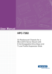
User Manual HPC-7140 1U Rackmount Server Chassis for MicroATX/ATX Server board with 4 x 3.5" Hot-swap Drive Bays and 1 full-height/halflength PCI-E x16 Expansion Slot Copyright The documentation and the software included with this product are copyright 2015 by Advantech Co., Ltd. All rights are reserved. Advantech Co., Ltd. reserves the right to make improvements in the products described in this manual at any time without notice. No part of this manual may be reproduced, copied, translated or transmitted in any form or by any means without the prior written permission of Advantech Co., Ltd. Information provided in this manual is intended to be accurate and reliable. However, Advantech Co., Ltd. assumes no responsibility for its use, nor for any infringements of the rights of third parties, which may result from its use. Acknowledgements HPC-7140 is a trademark of Advantech Co., Ltd. All other product names or trademarks are properties of their respective owners. On-line Technical Support For technical support and service, please visit our support website at: http://www.advantech.com/support Product Warranty (2 years) Advantech warrants to you, the original purchaser, that each of its products will be free from defects in materials and workmanship for two years from the date of purchase. This warranty does not apply to any products which have been repaired or altered by persons other than repair personnel authorized by Advantech, or which have been subject to misuse, abuse, accident or improper installation. Advantech assumes no liability under the terms of this warranty as a consequence of such events. Because of Advantech’s high quality-control standards and rigorous testing, most of our customers never need to use our repair service. If an Advantech product is defective, it will be repaired or replaced at no charge during the warranty period. For outof-warranty repairs, you will be billed according to the cost of replacement materials, service time and freight. Please consult your dealer for more details. If you think you have a defective product, follow these steps: 1. Collect all the information about the problem encountered. (For example, CPU speed, Advantech products used, other hardware and software used, etc.) Note anything abnormal and list any onscreen messages you get when the problem occurs. 2. Call your dealer and describe the problem. Please have your manual, product, and any helpful information readily available. 3. If your product is diagnosed as defective, obtain an RMA (return merchandise authorization) number from your dealer. This allows us to process your return more quickly. 4. Carefully pack the defective product, a fully-completed Repair and Replacement Order Card and a photocopy proof of purchase date (such as your sales receipt) in a shippable container. A product returned without proof of the purchase date is not eligible for warranty service. 5. Write the RMA number visibly on the outside of the package and ship it prepaid to your dealer. HPC-7140 User Manual Part No. 2001714000 Edition 1 Printed in Taiwan November 2015 ii Safety Instructions 1. 2. 3. 4. 5. 6. 7. 8. 9. 10. 11. 12. 13. 14. 15. 16. 17. 18. 19. Read these safety instructions carefully. Keep this User Manual for later reference. Disconnect this equipment from any AC outlet before cleaning. Use a damp cloth. Do not use liquid or spray detergents for cleaning. For plug-in equipment, the power outlet socket must be located near the equipment and must be easily accessible. Keep this equipment away from humidity. Put this equipment on a reliable surface during installation. Dropping it or letting it fall may cause damage. Do not leave this equipment in an environment unconditioned where the storage temperature under 0°C (32°F) or above 35°C (95°F), it may damage the equipment. The openings on the enclosure are for air convection. Protect the equipment from overheating. DO NOT COVER THE OPENINGS. Make sure the voltage of the power source is correct before connecting the equipment to the power outlet. Position the power cord so that people cannot step on it. Do not place anything over the power cord. All cautions and warnings on the equipment should be noted. If the equipment is not used for a long time, disconnect it from the power source to avoid damage by transient overvoltage. Never pour any liquid into an opening. This may cause fire or electrical shock. Never open the equipment. For safety reasons, the equipment should be opened only by qualified service personnel. If one of the following situations arises, get the equipment checked by service personnel: The power cord or plug is damaged. Liquid has penetrated into the equipment. The equipment has been exposed to moisture. The equipment does not work well, or you cannot get it to work according to the user's manual. The equipment has been dropped and damaged. The equipment has obvious signs of breakage. Caution: The computer is provided with a battery-powered real-time clock circuit. There is a danger of explosion if battery is incorrectly replaced. replace only with same or equivalent type recommended by the manufacture. discard used batteries according to the manufacturers instructions. THE COMPUTER IS PROVIDED WITH CD DRIVES COMPLY WITH APPROPRIATE SAFETY STANDARDS INCLUDING IEC 60825. CLASS 1 LASER PRODUCT KLASSE 1 LASER PRODUKT This device complies with Part 15 of the FCC rules. Operation is subject to the following two conditions: (1) this device may not cause harmful interference, and (2) this device must accept any interference received, including interference that may cause undesired operation Caution: Always completely disconnect the power cord from your chassis whenever you work with the hardware. do not make connections while the power is on. sensitive electronic components can be damaged by sudden power surges iii HPC-7140 User Manual 20. Caution: Always ground yourself to remove any static charge before touching the motherboard, backplane, or add-on cards. modern electronic devices are very sensitive to static electric charges. as a safety precaution, use a grounding wrist strap at all times. place all electronic components on a static-dissipative surface or in a static-shielded bag when they are not in the chassis 21. Caution: Any unverified component could cause unexpected damage. to ensure the correct installation, please always use the components (ex. screws) provided with the accessory box. A Message to the Customer Advantech customer services Each and every Advantech product is built to the most exacting specifications to ensure reliable performance in the harsh and demanding conditions typical of industrial environments. Whether your new Advantech equipment is destined for the laboratory or the factory floor, you can be assured that your product will provide the reliability and ease of operation for which the name Advantech has come to be known. Your satisfaction is our primary concern. Here is a guide to Advantech's customer services. To ensure you get the full benefit of our services, please follow the instructions below carefully. Technical support We want you to get the best performance possible from your products. If you run into technical difficulties, we are here to help. For the most frequently asked questions, you can easily find answers in your product documentation. These answers are normally a lot more detailed than the ones we can give over the phone. Please consult this manual first. If you still cannot find the answer, gather all the information or questions that apply to your problem, and with the product close at hand, call your dealer. Our dealers are well trained and ready to give you the support you need to get the most from your Advantech products. In fact, most problems reported are minor and can be easily solved over the phone. In addition, free technical support is available from Advantech engineers every businessday. We are always ready to give advice about application requirements or specific information on the installation and operation of any of our products. HPC-7140 User Manual iv Initial Inspection When you open the carton, please make sure that the following materials have been shipped: Chassis – 1 x HPC-7140 Chassis Components – 4 x 40*28 mm 4-pin PWM fan – 4 x HDD tray – 1 x SAS/SATA hard drive backplane Accessories – 1 x Accessory box with a package of screws – 2 x Key of HDD Tray If any of these items are missing or damaged, contact your distributor or sales representative immediately. We have carefully inspected the HPC-7140 mechanically and electrically before shipment. It should be free of marks and scratches and in perfect working order upon receipt. As you unpack the HPC-7140, check it for signs of shipping damage. (For example, damaged box, scratches, dents, etc.) If it is damaged or it fails to meet the specifications, notify our service department or your local sales representative immediately. Also, please notify the carrier. Retain the shipping carton and packing material for inspection by the carrier. After inspection, we will make arrangements to repair or replace the unit. v HPC-7140 User Manual HPC-7140 User Manual vi Contents Chapter 1 General Information ............................1 1.1 1.2 1.3 Introduction ............................................................................................... 2 Specifications ............................................................................................ 2 Redundant Power Supply Specifications (HPC-7140-R4A1E Only) ......... 2 Table 1.1: Power supply .............................................................. 2 Environment Specifications....................................................................... 2 Table 1.2: Environment specifications......................................... 2 Dimension Diagram................................................................................... 3 Figure 1.1 Dimension Diagram .................................................... 3 1.4 1.5 Chapter 2 System Setup .......................................5 2.1 2.2 Overview ................................................................................................... 6 Removing the Chassis Cover.................................................................... 6 2.2.1 Disconnecting the Chassis from the Power Source...................... 6 2.2.2 Removing the Chassis Cover ....................................................... 7 Figure 2.1 Removing the Chassis Cover ..................................... 7 Accessing the Hot-Swappable Drive Trays............................................... 8 2.3.1 Accessing and Installing Hard Drives ........................................... 8 Figure 2.2 Removing Hard Drive Carrier ..................................... 8 Installing Slim CD-ROM/DVD ROM .......................................................... 9 2.4.1 Storage Module Options ............................................................... 9 Figure 2.3 Installing the DVD-ROM Drive.................................... 9 Removing and Replacing the System Fans ............................................ 10 2.5.1 System Fans ............................................................................... 10 Figure 2.4 Installing the Fan Tray into the Chassis & Fan Tray Secured to the Chassis ............................. 10 Installing the Motherboard....................................................................... 11 2.6.1 Installing the I/O Shield ............................................................... 11 Figure 2.5 Installing the I/O Shield............................................. 11 Figure 2.6 Chassis Standoffs..................................................... 11 Figure 2.7 Installing the Motherboard ........................................ 12 Power Supply .......................................................................................... 13 Figure 2.8 Removing the Fixed Power Supply .......................... 13 Figure 2.9 Replacing the Redundant Power Supply.................. 14 2.3 2.4 2.5 2.6 2.7 Chapter Chapter 3 Operation............................................15 3.1 3.2 3.3 3.4 3.5 Overview ................................................................................................. 16 Figure 3.1 Chassis User Interface ............................................. 16 Control Panel Buttons ............................................................................. 16 Control Panel LEDs................................................................................. 17 Control Panel Board................................................................................ 18 Drive Carrier LEDs .................................................................................. 18 4 Rack installation ................................19 4.1 Rack Mounting Instructions..................................................................... 20 4.1.1 Identifying the Sections of the Rack Rails................................... 20 Figure 4.1 Identifying the Sections of the Rack Rails ................ 20 4.1.2 Locking Tabs............................................................................... 21 Figure 4.2 Identifying the Sections of the Rack Rails (right side rail vii HPC-7140 User Manual 4.1.3 4.1.4 4.1.5 4.1.6 4.1.7 4.1.8 Chapter shown)...................................................................... 21 The Inner Rail Extension (Optional)............................................ 21 Installing the Inner Rails ............................................................. 21 Figure 4.3 Assembling the Outer Rails...................................... 22 Outer Rack Rails......................................................................... 22 Installing the Outer Rails to the Rack ......................................... 22 Figure 4.4 Installing into a Rack ................................................ 22 Installing the Chassis into a Rack............................................... 23 Figure 4.5 Installing into an Open Rack .................... 23 Installing the Chassis into a Mid-mount Position (Telco) Rack... 23 5 1U 4Bay SAS Backplane .................. 25 5.1 5.2 An Important Note to Users .................................................................... 26 Front Connectors .................................................................................... 26 Figure 5.1 Front Connectors...................................................... 26 Figure 5.2 SAS Ports................................................................. 26 HPC-7140 User Manual viii Chapter 1 1 General Information 1.1 Introduction HPC-7140 is a 1U rackmount industrial computer chassis for high-performance and high-capacity computing applications. It meets a variety of application needs for filing, printing, e-mail and web serving. This powerful computing platform is suitable for mission-critical computer telephony applications, industrial automation, and factory management. A wide range of standard computing peripherals can be integrated with the chassis to meet different application needs for operation under harsh conditions 24 hours a day, 7 days a week. 1.2 Specifications Construction: Heavy-duty steel Disk Drive Capacity: One slim-type ODD Bay LED Indicators on Front Panel: Power, HDD activity, LAN status and system information Switch and Button on Front Panel: Power switch, system reset button Front I/O Interfaces: Two USB2.0 ports, one COM port Cooling System: Four 40 mm x 28 mm hot-swappable cooling fans Weight: 10 kg Dimensions (W x H x D): 437 x 43 x 504 mm 1.3 Redundant Power Supply Specifications (HPC7140-R4A1E Only) Table 1.1: Power supply Model 1+1 400 W redundant power supply Watt 400 W AC-DC power supply Input Rating 100 - 240 V, 50-60 Hz, 10-5 Amp Safety UL/TUV/CB/CCC 1.4 Environment Specifications Table 1.2: Environment specifications Environment Operating Non-operating Temperature 0° C ~ 35° C -40° C ~ 70° C Humidity 10 ~ 85% @ 40° C Non-Condensing 10 ~ 95% @ 40° C Non-Condensing HPC-7140 User Manual 2 Chapter 1 1.5 Dimension Diagram General Information Figure 1.1 Dimension Diagram 3 HPC-7140 User Manual HPC-7140 User Manual 4 Chapter 2 System Setup 2 2.1 Overview The following procedures instruct users on how to install a motherboard, add-on cards and disk drives into the HPC-7140. Caution! Use caution when installing or operating the components with the chassis open. Be sure to turn off the power, unplug the power cord and ground yourself by touching the metal chassis before you handle any components inside the machine. 2.2 Removing the Chassis Cover 2.2.1 Disconnecting the Chassis from the Power Source 1. 2. 3. Turn off all peripheral devices and turn off the power supply to the HPC-7140. Disconnect the AC power cords from the system. Disconnect all cables and label the cables for easy identification. Warning! Use a grounded wrist strap designed to prevent static discharge when handling components. After completing the above steps, you can remove the chassis cover and install components and devices into the chassis as described in this chapter. HPC-7140 User Manual 6 Chapter 2 2.2.2 Removing the Chassis Cover System Setup Figure 2.1 Removing the Chassis Cover 1. 2. 3. 4. Power down the system and unplug the power cord from the rear of the power supply. Simultaneously press both release tabs. Slide the cover back toward the rear of the chassis. Lift the cover upwards and off of the chassis. Warning! Except for short periods of time, do NOT operate the server without the cover in place. The chassis cover must be in place to allow proper airflow and prevent overheating. 7 HPC-7140 User Manual 2.3 Accessing the Hot-Swappable Drive Trays Hot-swappable drives may be removed and installed from the chassis without powering-down the system and without opening the chassis cover. 2.3.1 Accessing and Installing Hard Drives Figure 2.2 Removing Hard Drive Carrier HPC-7140 supports four hot-swappable 3.5" hard drives. Only SAS or enterprise level hard drives are recommended. The hard drives in your chassis may look slightly different than the ones shown in this manual. Removing Hard Drive Carriers from the Chassis 1. Press the release button on the drive carrier. This extends the drive bay handle. 2. Use the handle to pull the drive out of the chassis. HPC-7140 User Manual 8 2.4.1 Storage Module Options 1. 2. 6. Figure 2.3 Installing the DVD-ROM Drive HPC-7140 chassis models include space for one optional DVD-ROM drive. Installing the DVD-ROM Drive 1. Power down the system and unplug the power cord from the rear of the power supply. Open the chassis cover as described in Section 1-3. 2. Secure the left rail (A) to the left side of the DVD-ROM drive using two screws (B). 3. Attach the right rail (C) to the right side of the DVD-ROM drive using two screws (D). 4. Carefully slide the DVD-ROM drive and into the chassis. 5. Plug the power cord into the power supply and power up the system. 9 HPC-7140 User Manual System Setup 3. 4. 5. Insert the CD-ROM/DVD-ROM SATA cable through the B/P bracket. Connect the CDROM/DVD-ROM SATA cable with the Slim CD-ROM/DVDROM. Release thumb screw to remove the Slim CD-ROM/DVD-ROM holder bracket. Remove the Slim CD-ROM /DVD-ROM dummy plate. There are 2 pins on chassis as shown. Align the Slim CD-ROM/DVD-ROM onto these pins. Align these 2 pins of Slim CD-ROM/DVD-ROM holder bracket into the left of Slim CD-ROM/DVD-ROM & tighten the thumb screw. Chapter 2 2.4 Installing Slim CD-ROM/DVD ROM 2.5 Removing and Replacing the System Fans Before installing the motherboard in the chassis or accessing the motherboard after installation, it is necessary to remove the system fans. One set is located at the rear of the chassis, the other set is located in the middle of the chassis. 2.5.1 System Fans HPC-7140 chassis includes four heavy-duty fans with open slots for two additional fans to provide cooling for the chassis. These fans circulate air through the chassis to lower the chassis internal temperature. Replacing a System Fan 1. If necessary, open the chassis as described in Section 1-3 while the power is running to determine which fan requires changing. (Never run the server for an extended period of time with the chassis open.) 2. Power down the system and unplug the power cord from the rear of the power supply. If not already open, open the chassis cover as described in Section 1-3. 3. Remove the failed fan's power cord from the motherboard. 4. Remove the screws securing the fan tray to the chassis. 5. Gently push upward from the underside of the fan, sliding it out through the opening in the top of the fan tray. 6. Place the new fan into the vacant space in the housing. Make sure that the arrows on the top of the fan (indicating air direction) point in the same direction as the arrows on the other fans. 7. Plug the power cord into the rear of the power supply, power up the system and check that the fan is working properly before replacing the chassis cover. Figure 2.4 Installing the Fan Tray into the Chassis & Fan Tray Secured to the Chassis HPC-7140 User Manual 10 2.6.1 Installing the I/O Shield The I/O shield holds the motherboard ports in place. Install the I/O shield before installing the motherboard. If the motherboard you purchased did not include a standard I/O shield, contact the motherboard vendor for a compatible shield. Figure 2.5 Installing the I/O Shield Chassis Standoffs Figure 2.6 Chassis Standoffs 11 HPC-7140 User Manual System Setup Installing the I/O Shield 1. Review the documentation that came with your motherboard. Become familiar with component placement, requirements, and precautions. 2. Power down the system and unplug the power cord from the rear of the power supply. Open the chassis cover as described in Section 1-3. 3. With the illustrations facing the outside of the chassis, place the shield into the space provided at the rear of the chassis as illustrated below. 4. Replace the chassis cover, plug the power cord into the rear of the power supply and power up the system. Chapter 2 2.6 Installing the Motherboard Permanent and Optional Standoffs Standoffs prevent short circuits by securing space between the motherboard and the chassis surface. HPC-7140 chassis includes permanent standoffs in locations used by most motherboards. These standoffs accept the rounded Phillips head screws included in the HPC-7140 accessories packaging. Some motherboards require additional screws for heatsinks, general components and/or non-standard methods to secure them. Optional standoffs are included for these motherboards. To use an optional standoff, you must place the hexagonal screw through the bottom the chassis and secure the screw with the hexagon nut (rounded side up). Compare the mounting holes in the motherboard to those in the chassis and add or remove standoffs as needed. Installing the Motherboard 1. Review the documentation that came with your motherboard. Become familiar with component placement, requirements, precautions, and cable connections. 2. Power down the system and unplug the power cord from the rear of the power supply. Open the chassis cover as described in Section 1-3. 3. As required by your motherboard, install standoffs in any areas that do not have a permanent standoff. To do this: a. Place a hexagonal standoff screw through the bottom the chassis. b. Secure the screw with the hexagon nut (rounded side up). 4. Lay the motherboard on the chassis aligning the permanent and optional standoffs 5. Secure the motherboard to the chassis using the rounded, Phillips head screws. Do not exceed eight pounds of torque when tightening the screws. 6. Secure the CPU(s), heatsinks, and other components to the motherboard as described in the motherboard documentation. 7. Connect the cables between the motherboard, backplane, chassis, front panel, and power supply, as needed. Also, the fans may be temporarily removed to allow access to the backplane ports. 8. Replace the chassis cover, plug the power cord into the rear of the power supply and power up the system. Figure 2.7 Installing the Motherboard HPC-7140 User Manual 12 HPC-7140 chassis has one single power supply, or comes with two redundant power supplies. Figure 2.8 Removing the Fixed Power Supply 8. Use Flex-ATX power supply, add one bracket fix on power supply with 3 flat screws, as illustrated below. HPC-7140-R4A1E model chassis features redundant power supplies. The power supply can be changed without powering-down the server. 13 HPC-7140 User Manual System Setup Changing a Single Power Supply 1. Power down the system and unplug the power cord from the rear of the power supply. Open the chassis cover as described in Section 1-3. Lay the chassis on a flat, stable surface and remove the chassis cover. 2. Remove the two screws, located on the end of the power supply bay, as illustrated below. Set the screws aside for later use. 3. Gently slide the power supply out of the back of the chassis. 4. Replace the failed power module with another of the same model. 5. Slide the new power supply module into the power supply bay. 6. Align the holes in the power supply with the holes in the power supply bay and secure the power supply using the two screws which were set aside in step 2. 7. Replace the chassis cover, plug the power cord into the rear of the power supply and power up the system. Chapter 2 2.7 Power Supply Changing a Redundant Power Supply 1. Press the release button on the failed power supply. 2. Use the handle to gently slide the power supply out the back of the chassis. 3. Replace the failed power module with another of the same model. 4. Slide the new power supply module into the power supply bay until it clicks into the locked position. Figure 2.9 Replacing the Redundant Power Supply HPC-7140 User Manual 14 Chapter 3 Operation 3 3.1 Overview There are several LEDs on the control panel as well as others on the drive carriers to keep you constantly informed of the overall status of the system as well as the activity and health of specific components. HPC-7140 has three push-buttons on the control panel: a UID button, a reset button and an on/off switch. This chapter covers these buttons, and explains the meanings of all LED indicators and the appropriate responses you may need to take. Figure 3.1 Chassis User Interface 3.2 Control Panel Buttons There are three push-buttons located on the front of the chassis. These are (in order from left to right) a UID button, a reset button and a power on/off button. Power: The main power switch is used to apply or remove power from the power supply to the server system. Turning off system power with this button removes the main power but keeps standby power supplied to the system. Therefore, you must unplug system before servicing. Reset: The reset button is used to reboot the system. HPC-7140 User Manual 16 The control panel located on the front of HPC-7140 chassis has five LEDs. These LEDs provide you with critical information related to different parts of the system. This section explains what each LED indicates when illuminated and any corrective action you may need to take. Chapter 3 3.3 Control Panel LEDs Operation NIC2: Indicates network activity on GLAN2 when flashing. NIC1: Indicated network activity on GLAN1 when flashing. HDD: Indicated IDE channel activity. SAS/SATA drive and/or DVDROM drive activity when flashing. Power: Indicates power is being supplied to the system’s power supply units. This LED should normally be illuminated when the system is operating. 17 HPC-7140 User Manual 3.4 Control Panel Board ߑ 偖 ߓ ߔ ߕ ߖ 1. 2. 3. 4. 5. 6. 7. 8. ߗ ߘ Front control board connector (2 x 8 pins) JP3 OH LED light D5 NIC2 LED light D4 NIC1 LED light D3 HDD LED light D2 PWR LED light D1 Reset switch JP2 PWR switch JP1 3.5 Drive Carrier LEDs Your chassis uses SAS or SATA, but not both at the same time. SAS/SATA Drives Each SAS/SATA drive carrier has two LEDs. Green: Each Serial ATA drive carrier has a green LED. When illuminated, this green LED (on the front of the SATA drive carrier) indicates drive activity. A connection to the SATA backplane enables this LED to blink on and off when that particular drive is being accessed. Red: The red LED indicates a SAS/SATA drive failure. If one of the SAS/SATA drives fail, you should be notified by your system management software. HPC-7140 User Manual 18 Chapter 4 Rack installation 4 4.1 Rack Mounting Instructions This section provides information on installing HPC-7140 chassis into a rack unit with the rails provided. There are a variety of rack units on the market, which may mean the assembly procedure, will differ slightly. You should also refer to the installation Instructions that came with the rack unit you are using. Note! This rail will fit a rack between 26" and 33.5" deep. 4.1.1 Identifying the Sections of the Rack Rails The chassis package includes two rack rail assemblies in the rack mounting kit. Each assembly consists of two sections: an inner fixed chassis rail that secures directly to the server chassis and an outer fixed rack rail that secures directly to the rack itself. Front Inner Rails Figure 4.1 Identifying the Sections of the Rack Rails HPC-7140 User Manual 20 Both chassis rails have a locking tab. The tabs lock the server into place when installed and pushed fully into the rack. These tabs also lock the server in place when fully extended from the rack. This prevents the server from coming completely out of the rack when you pull it out for servicing. 4.1.3 The Inner Rail Extension (Optional) The inner rails are pre-attached and do not interfere with normal use of the chassis if you decide not to use a server rack. Attach the inner rail extension to stabilize the chassis within the rack. If you are not using a rack, you do not have to install the inner rail extensions. 4.1.4 Installing the Inner Rails 1. 2. 3. Place the inner rack extensions on the side of the chassis aligning the hooks of the chassis with the rail extension holes. Make sure the extension faces "outward" just like the pre-attached inner rail. Slide the extension toward the front of the chassis. Secure the chassis with two screws as illustrated. Repeat steps for the other inner rail extension. Warning! Do not pick up the server by the front handles. They are designed to pull the system from a rack only. 21 HPC-7140 User Manual Rack installation Figure 4.2 Identifying the Sections of the Rack Rails (right side rail shown) Chapter 4 4.1.2 Locking Tabs Figure 4.3 Assembling the Outer Rails 4.1.5 Outer Rack Rails Outer rails attach to the server rack and hold the server in place. The outer rails for HPC-7140 chassis extend between 30 inches and 33 inches. 4.1.6 Installing the Outer Rails to the Rack 1. 2. 3. 4. Attach the short bracket to the outside of the long bracket. You must align the pins with the slides. Also, both bracket ends must face the same direction. Adjust both the short and long brackets to the proper distance so that the rail fits snugly into the rack. Secure the long bracket to the front side of the outer rail with two M5 screws and the short bracket to the rear side of the outer rail with three M5 screws. Repeat steps 1-4 for the left outer rail. Figure 4.4 Installing into a Rack Note! Figures are for illustrative purposes only. Always install servers into racks from the bottom up. HPC-7140 User Manual 22 1. 2. 3. 4. Figure 4.5 Installing into an Open Rack Note! Figures are for illustrative purposes only. Always install servers into racks from the bottom up. 4.1.8 Installing the Chassis into a Mid-mount Position (Telco) Rack 1. 2. 3. 4. Use the two L-shaped brackets on either side of the chassis (four total). Determine how far the chassis will extend out the front of the rack. Larger chassis should be positioned to balance the weight between front and back. If a bezel is included on your server, remove it. Attach the two front brackets to each side of the chassis, then the two rear rackets positioned with just enough space to accommodate the width of the telco rack. Finish by sliding the chassis into the rack and tightening the brackets to the rack. 23 HPC-7140 User Manual Rack installation Confirm that chassis includes the inner rails and rail extensions. Also, confirm that the outer rails are installed on the rack. Line chassis rails with the front of the rack rails. Slide the chassis rails into the rack rails, keeping the pressure even on both sides (It may be necessary to depress the locking tabs when inserting). When the server has been pushed completely into the rack, the locking tabs will "click" into the locked position. (Optional) Insert and tightening the thumbscrews that holds the front of the server to the rack. Stability hazard. The rack stabilizing mechanism must be in place, or the rack must be bolted to the floor before you slide the unit out for servicing. Failure to stabilize the rack can cause the rack to tip over. Chapter 4 4.1.7 Installing the Chassis into a Rack HPC-7140 User Manual 24 Chapter 5 1U 4Bay SAS Backplane 5 5.1 An Important Note to Users All images and layouts shown in this user's guide are based upon the latest PCB revision available at the time of publishing. The card you have received may or may not look exactly the same as the graphics shown in this manual. 5.2 Front Connectors Figure 5.1 Front Connectors Front Connectors 1. Power connectors (4-pins) J3, J4 2. SATA connectors (7-pins) SATA1, SATA2, SATA3, SATA4 Figure 5.2 SAS Ports 3. 4. LED indicators LED1, LED2, LED3, LED4, LED5, LED6, LED7, LED8 SAS connectors (22-pins) J1, J2, J5, J6 HPC-7140 User Manual 26 Chapter 5 1U 4Bay SAS Backplane HPC-7140 User Manual 27 www.advantech.com Please verify specifications before quoting. This guide is intended for reference purposes only. All product specifications are subject to change without notice. No part of this publication may be reproduced in any form or by any means, electronic, photocopying, recording or otherwise, without prior written permission of the publisher. All brand and product names are trademarks or registered trademarks of their respective companies. © Advantech Co., Ltd. 2015