1
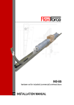
manual GB RES350 hardware set residential (garage) overhead doors built in dimensions 350mm INSTALLATION / MAINTENANCE © All rights reserved. Flexi-Force®, 2006 FF-MANUAL RES350/ www.flexiforce.com manual GB ATTENTION! GENERAL WARNINGS! o install, use and maintain this hardware set safely, a number of precautions T must be taken. For the safety of all concerned pay heed to the warnings and instructions given below! If in doubt, contact your supplier. pecial safety warnings or remarks in this manual are indicated with this S symbol:read these warnings carefully. This manual has been written for use by experienced fitters and as such is not suitable for d.i.y. purposes or for use by trainee fitters. This manual describes the installation of the hardware set components, door sections (panels) and refers to installation manuals of the electrical operator. Be sure to supplement this manual if needed with instructions for any additional components not described in this manual. Before starting, read this manual carefully! Certain components may be sharp or have jagged edges. As such you are advised to wear safety gloves. All the components which have been supplied are designed for use with this specific overhead door. Replacement or adding additional components may have an adverse effect on the safety of, and the guarantee on, the door. Also the CE-approval which has been granted to this door will be cancelled when components are changed or installation is not done according to this manual! Installer is responsible for this. During tensioning, springs can exert large forces. Work carefully. Use the proper equipment. Ensure that you are standing in a steady position. Ensure that there is sufficient light during installation. Remove obstacles and dirt. Make sure that there is no one else present other than the fitters. Other people (children!) may get in the way or endanger themselves during the installation. GARANTIE, CONDITIES EN VOORWAARDEN The general terms and conditions of delivery and payment issued by the Metaalunie and designated as METAALUNIE CONDITIONS are fully applicable to all our quotations, contracts and their implementation. We expressly reject all other terms and conditions. On request we will send you a copy of these terms and conditions free of charge. A copy may also be downloaded from our website www.flexiforce.nl. CONTACT Flexi-Force Group B.V., P.O. Box 37, 3770 AA Barneveld, The Netherlands Tel. +31-(0)342-427777, [email protected] FF-MANUAL RES350/ www.flexiforce.com manual GB INDEX - Warranty, terms and conditions - Introduction - Tools required for correct and rapid assembly - Control dimensional details - Assembly vertical track set - Assembly horizontal track set - Assembly top seal - Assembly and fitting of spring package - Fitting the door panels - Fitting cable and tensioning of the spring set - Finishing the door - Option electric drive - Panel assembly - Assembly instructions spring breaking device 651, 667 incl. BG-approval Enclosure - Installation and user instructions electric drive (option) Enclosure - Additional information Additional information INTRODUCTION Flexi-Force has a complete programme of hardware sets, especially for residential (garage) overhead doors. The set RES350 includes the following features: - Suitable for single and double garages to CW > 5000mm, 160 kg - Springs in front at lintelEnkele horizontale rails - Fitted with cable within the tracks and spring break device meeting CE standards - installation height 350mm In this handbook we shall restrict our instructions for the proper assembly of our hardware set parts. For the installation of the complete door, including any components added by the supplier, as well as for a user handbook, we refer you to the supplier of the complete overhead door who is also responsible for the correct CE marking of the door. The track set (vertical and horizontal) Standard parts and/or fixing material. (including spring break device) Fittings (hinges, ground console, top roller holder etc.) in version selected The cable set Tube shaft Torsion springs (galvanized or powder coated) in version selected Connection /suspension profiles for horizontal track set Top seal for on the lintel Electric drive (RES-E-500) drawbar type 1 box packaging Warning labels We wish you every success with the installation of this hardware set. If anything is unclear or should you have queries, you should of course contact Flexi-Force B.V. FF-MANUAL RES350/ www.flexiforce.com manual GB TOOLS REQUIRED FOR CORRECT AND RAPID ASSEMBLY (Battery) drill with Bit 4.0 mm Bit 4.5 mm Bit 6.5 mm Plug 10mm Plug 13 mm Hexagonal key 4 mm Ring /open ended spanner10 mm Ring /open ended spanner13 mm Ring /open ended spanner15 mm Ring /open ended spanner17 mm Socket wrench with ¼” square Wrench Gluing clamp Cord Water level (hose) 2 blocks of ca. 20 en 40mm in height CHECKING DIMENSIONAL DETAILS Before assembling the set the details below should be checked on the basis of this figure. Figure A = Clear width B = Clear height C = Side area D = Top area Panel assembly See enclosure A Installation area required Side area C: minimum 85 mm (117 mm when using hook 2602) Clear passage height based on manually operated flat panel:DMH Re 1) W hen you have a minimum installation height behind the spring package (above the hor. extension tracks) we advise you to fir the top seal to the lintel, see “assembly top seal”. Re 2) T he upper area required will depend on the height of the drive rod of the electrical drive. FF-MANUAL RES350/ www.flexiforce.com manual GB ASSEMBLY VERTICAL TRACK SET 11 First mark “A” en “B” on both piers using a spirit level or water level hose and then mark “C” (Figure) 21 Fit both vertical tracks with the lower surface on mark line C and the edge 64 mm along the pennant (Figure). The two bearing tracks should be parallel to one another. For fitting to brickwork a angle bracket (2602) may be used. 31 For sloping floors, one of the bearing tracks may be compensated (for example with a wedge). ASSEMBLY HORIZONTAL TRACK SET 41 Attach a piece of cord to the ceiling or the roof structure to maintain the elevation of the rear side of the horizontal tracks during the assembly process. 51 Fit the horizontal tracks to the vertical bearing tracks. See figure. the extremity of the bend in line with the horizontal tracks. Fit the M6 flanged nuts (1062M) and secure them hand-tight. ASSEMBLY TOP SEAL 61 Fit the sealing profile (1085) to the lintel using the 4 spring clips (1083) (figure). 4 pieces for DMB <3000, 6 pieces for DMB> 3000. The top sealing profile (1085) replaces the top rubber 1036-36. This prevents the top rubber (1036-36) scraping along the ceiling. FF-MANUAL RES350/ www.flexiforce.com manual GB FITTING TO FIXED POINT. 71 Depending on the option selected, one of the following instructions will be appropriate. The construction (and fitting) for suspension of the horizontal tracks will depend on others. With suspension profile for horizontal tracks to ceiling or roof structure (Figure ). Make using the perforated angle line (30B0750) a connection between the track fastening plate and ceiling /roof structure. With horizontal interconnecting profile between the horizontal tracks (Figure ). Fit the angle bracket (2602) with 2x press bolt (1062B) and 2x flanged nut (1062M) to the end of the upper horizontal tracks Assembly and fitting of spring package 81 CW < 3000 en CH <2500 Slide the tube spindle (CH< 2500 701, CW>2500 705GB) through both springs. The tension plug of the anti-clockwise wound spring is coded black and should be fitted on the left. See figure 91 CW > 3000 Slide each of the two cottered tube shafts (705GB) through a spring. The tube shafts are of unequal lengths to avoid the coupling (703ST) from the centre, and when there is an electric drive, sitting under the drawbar. The tension plug of the left-wound plug is coded black and should be fitted on the left. See figure. Fit to both shafts a bearing (USA-B) and a bearing holder (325) each with 2 M8 pressed bolts and nuts (1070-3.5B and 1068M) to the bearing plate (USA-MINI). Then fit disassembled halves of the coupler (703ST) (711A-38). FF-MANUAL RES350/ www.flexiforce.com manual GB 101 Fit the spring break devices (651LH/RH or 667LH/RH) to the stationary spring plugs, following the drawings that are included in the packaging with every spring break device. ! See handbook enclosed for the 651/667 spring break device. 111 Slide on both sides a cable drum (FF-4X8 or FF-4-13) onto the shaft. The cable drum coded RH, should be fitted on the left side. Turn the securing bolts of the cable drum to secure these hand-tight to the tube shaft. Secure each cable drum FF-4-13 with a cotter (711A-75). 121 Fit the bearing plate/spring rupture protection assemblies with a spring package on the wall FITTING THE DOOR PANELS General In order to insert the self-tapping screws into the panels holes have to be drilled. The diameter of the holes will depend on the panel material. Guideline value for steel insulated panels is 4.5 mm. 131 Place the bottom panel truly level between the bearing tracks on ca 20 to 40 mm high blocks. 141 Hook the loop of the lifting cable ( k3....) to the pin intended for that purpose on the bottom bracket. Insert the shaft of the bearing roller (574-100) through the spacer (2066-07) and the holes of the bottom bracket (422LH/RH) intended for that purpose. Place then the bearing roller first in the bearing track and then secure the bottom brackets with the self-tapping screws (1055BV) Figure. 151 Place the remaining panels and secure the side and central hinges (may be pre-fitted) to the panels (Figure) DMB < 3000 1 central spring per section, DMB > 3000 and < 5000 several central springs depending on the panel type and clear width. See appendix in order to determine which type of hinge may be employed. FF-MANUAL RES350/ www.flexiforce.com manual GB 161 Adjust the bearing roller to the side hinge such that the nylon-bearing roller is located in the rounding of the track and that the play between panel and side seal is at a minimum. The shaft of the bearing roller should remain capable of turning by hand. 171 Slide the shaft of the bearing roller (574-100) into the sleeve of the top roller holder. Place the bearing roller in the shortened bend and fix the top roller holder (417) to the upper side of the top panel with 4 self-tapping screws (1055BV) (Figure). FITTING CABLE AND TENSIONING THE SPRING PACKAGE 181 Align the shaft. 191 Guide the cable from the bottom bracket, behind the bearing roller shafts to the cable drum. See fig. 201 Hook the end of the cable with the end of the pressure clamp (circular) into the cable drum and turn the cable drum until the lifting cable is taut. Align the cable drum in such fashion that the lifting cable is free to wind up. Secure finally the drum with the hexagon bolts to the shaft without keyway (tightening moment 10Nm). For a tube shaft with a keyway the drum must be secured with a cotter (711A-75) and bolts. 211 Block the shaft with for example a wrench. 221 Secure the other cable in the same fashion. Both cables must be tensioned equally while the door panel is truly level. 231 Ensure that the door does not elevate. You can do this for example by placing wrenches in the vertical bearing tracks. 241 Tension the springs by the prescribed number of turns (see packaging list in the box), pull the spring ± 5 mm apart (to reduce friction) and secure the spring to the tube shaft using the screws of the tension plug (17 Nm). CAUTION! Torsion springs are subject to considerable tension. Proceed at all times with extreme caution. Instal¬lation, maintenance and repair should be carried out only by experienced and properly trained overhead door fitters. Use correctly fitting and properly maintained tension levers. Tensioning the spring a. Make sure that the marking strip on the spring forms a sharp line b. Insert the 1st tension lever completely into the tensioning slot. FF-MANUAL RES350/ www.flexiforce.com manual GB c. d. e. f. g. h. i. j. k. Turn the 1st tension lever a quarter turn such the spring is tensioned. Insert the 2nd tension lever completely into the following tensioning slot. Take over the tension of the spring from the 1st tension lever to the 2nd tension lever. Remove the 1st tension lever from the slot. Turn the 1st tension lever a quarter turn such the spring is tensioned. Repeat steps 2 through 7 until the spring has realized the prescribed number of turns. Secure the spring plug on the shaft by turning the bolts in the tension plug in the tube shaft. Remove the final tension lever. Check the number of turns by counting the number of turns that the marking strip has made. Number of turns spring: CH 4 panels 5 turns 2100 7.1 turns 6.8 turns 2125 7.6 turns 7.3 turns 2250 8.0 turns 7.7 turns 2375 8.4 turns 8.7 turns 2500 8.5 turns9.2 turns 251 Remove the restriction from the door in the tracks and from the shaft and check whether the door is properly balanced. When this is not the case you should correct this by tensioning or relaxing by at most 1 turn per spring. Make sure when doing this that both springs are equally corrected. Correction of the spring tension a. Insert the 1st tension lever completely into the tension slot. b. Take over the tension from the spring with this tension lever. c. Loosen the bolts in the tension plug. d. Turn the 1st tension lever in the direction required. e. Insert the 2nd tension lever completely in the next tension slot. f. Take over the tension of the spring from the 1st tension lever to the 2nd tension lever. g. Remove the 1st tension lever from the slot. h. Turn the 2nd tension lever a quarter turn in the direction required. i. Insert the 1st tension lever completely into the next tension slot. j. Take over the tension of the spring from the 1st tension lever to the 2nd tension lever. k. Repeat steps 4 through 10 until the correction required has been realized. l. Secure the spring plug on the shaft by turning the bolts in the tension plug in the tube shaft. m. Remove the final tension lever. 261 When the door panel is not hanging completely horizontally in the lifting cables in (almost) closed conditions there are three options for fine adjustment. A. Loosen slightly from the bearing plate the securing bolts of the spring break device and adjust the bearing plate upwards or downwards. B. Loosen the securing bolts of the cable drum and the drum relative to the tube shaft. C. When a coupling is employed this may be adjusted to ensure a better horizontal setting. 271 Close the door and secure the door panel. Press the top panel against the side (upper) seal and slide the top roller holder as far as possible (minimum play between door panel and seal). FF-MANUAL RES350/ www.flexiforce.com manual GB FINISHING THE DOOR 281 Fit any additional accessories that you have ordered separately such as: Handgrip, Lock, Bolt, a bolt may not be fitted to an electrically driven door. 291 Fit the rubber doorstop supplied with a pressed bolt M6x16 (1062B) and nut M6 1062M), to the end of the horizontal tracks (Figure). 301 Lubricate all hinges and bearing rollers with a drop of oil. 311 Grease the cables. 321 Grease the bearing roller shafts. 331 The torsion springs are already lightly oiled. 341 Place your CE identification plate on the door together with any warning labels required. NB! Place a warning label on the lower curve because fingers or hands could be trapped between curve and panel when the door is moving. 351 Hand over necessary documents to the end-user: 1 User manual 2 Dismantling instructions (included in this manual) 3 Maintenance instructions (included in the user manual) 4 Service log book 5 Declaration of conformity IIa declaring the door is according to EN-13241-1. NB! WITH THIS DOOR NO ROPE IS BEING SUPPLIED. DO NOT INSTALL A ROPE WITH A POWER OPERATED DOOR AT ANY TIME!! THIS CAN CAUSE SERIOUS INGOURIES OR DANGER TO THE USER OF THE DOOR! OPTION ELECTRICAL DRIVE When you have selected option I. Electrical drive (RES-E-500), then this should be assembled in conformity with the handbook supplied with the drive. You should clearly follow the instructions for electrical operation in this handbook. In order to maintain the closing force of the door within the standards set the attachment (97014) point of the drawbar should be 230 mm from the upper hinge point. NB! De persoon die de deur installeert dient grondig te controleren of deze deur veilig met de gekozen aandrijving kan worden gecombineerd. (ITT REPORT 0402-CPD-402201.) Denk daarbij aan de maximale piekkracht die toegestaan is als de deur wordt gesloten. Er kunnen mensen gewond raken als de software-instellingen of de installatie van de aandrijving, of de geselecteerde aandrijving voor deze deur niet goed zijn gecontroleerd!! FF-MANUAL RES350/10 www.flexiforce.com manual GB GENERAL SYSTEM DRAWING FF-MANUAL RES350/11 www.flexiforce.com manual GB E = A + 45 F = B + 15 (See also figure ) (See also figure ) Enclosure A NB! Make sure that the bottom panel will not be cut for adjusting the panel or door height. This should be done with the top section only! The attachment of the bottom bracket, which is holding the complete door weight, is relying on the construction of the panel. Danger can occur if the panel is cut at this point. FF-MANUAL RES350/12 www.flexiforce.com manual GB TROUBLESHOOTING : What should be checked if the door is not balanced properly? When a door is not well in balance, then it is necessary to check first the following details : 1. Is the given information correct : - - weight of the door leaf (including hardware) is the division of the weight equal on each panel, or are there panels with a different weight than the others, for instance by the application of different panels (glass, pass door with heavy profiles). 2. Were the correct parts supplied and fitted? - especially the drums and springs are important : - correct dimensions supplied ? 3. Is the door properly installed? - 4. Were modifications made afterwards ? - 5. horizontal tracks really horizontally and not with inclination. heck if any changes were made during the fitting, or if a pass door was fitted later, or any reinforcement profiles fitted etc. Is the e-operator installed and selected properly? - - - Is the installed e-operator suitable for this door? Is the e-operator power adjusted properly for this door? (See installation manual operator) Is the connection of the drawbar to the top-panel on the right position? (See attachment and manual operator). WHAT TO DO AFTER CABLE BREAK OR SPRING BREAK? NB! Also make sure to instruct the user about this. After spring breaking the door will be stopped by the 651LH/RH or 667LH/RH spring break device. The end user must contact immediately a qualified overhead door mechanic. The spring breaking device is a so called “one-shot” device. After it has acted, it must be replaced, together will all other possibly damaged components of the door, such as torsion springs, spring plugs, bearing plates etc. The door has to be inspected thouroughly. We refer to the separate manual for the 651/667 spring break devices on our website: www.flexiforce.com / downloads / manuals. After cable breaking, the door will be stopped by the second cable, which is designed to be strong enough to hold the weight of the door. Again, qualified overhead door mechanics must inspect the door and replace all possibly damaged components, such as: bottom brackets, cable, roller carriers, rollers, etc. FF-MANUAL RES350/13 www.flexiforce.com manual GB DISMANTLING THE OVERHEAD DOOR ATTENTION! WARNING! To dismantle an existing overhead door, a number of precautions must be taken. For the safety of all concerned pay heed to the warnings and instructions given below! If in doubt, contact your supplier. Dismantling should only be carried out by experienced fitters. This manual is not suitable for d.i.y. purposes or for use by trainee fitters. This manual only describes the installation/dismantling of hardware for overhead doors and as such must be supplemented with instructions for any additional components. FOR ANY DETAILS ON THESE DISMANTLING INSTRUCTIONS, WE REFER TO THE INSTALLATION CHAPTERS OF THIS MANUAL WHERE DRAWINGS AND DETAILS ARE DISPLAYED. STEP 1. De-tensioning the torsion spring(s) CAUTION ! Torsion springs and bottom brackets are under high tension. Exercise at all times great caution. Use properly fitting and maintained tension irons (see drawing). Start dismantling of the door by closing the door and securing its movement with a clamp on the vertical track. First the tension on the torsions springs and cable has to be released. Do this by following these instructions : 1 2 3 4 5 6 7 8 9 10 11 12 Insert the 1st tensioning iron fully into the tensioning aperture. Take over the tension of the spring with this tensioning iron. Loosen the bolts in the tensioning plug and remove the key. Turn the 1st tensioning iron in the direction required. Insert the 2nd tensioning iron fully into the next tensioning aperture. Take over the tensioning of the spring from the 1st tensioning iron with the 2nd tensioning iron. Remove the 1st tensioning iron from the aperture. Turn the 2nd tensioning iron a quarter turn in the direction required. Insert the 1st tensioning iron fully into the tensioning aperture. Take over the tensioning of the spring from the 2nd tensioning iron with the1st tensioning iron. Repeat steps 4 through 10 until all tension is released. Remove the last tensioning iron. FF-MANUAL RES350/14 www.flexiforce.com manual GB STEP 2. Disconnect the electrical operator. Follow any instructions given in the separate manual of the operator. STEP 3. Loosen the cable drums and remove the keys. Act carefully, there might be some tension left on the cable. Check if the cable is slack. Remove the cable by disconnecting it from the bottom bracket and cable drum. STEP 4. Dismantle the horizontal track construction. STEP 5. Remove the panels one by one from the vertical track construction, starting with the top panel. Do this by loosening the hinges and rollers first. STEP 6. Remove the shaft construction from the lintel, after you have dismantled the E-operator from the shaft. If the shaft is divided and connected with a coupler, first disconnect the coupler and carefully remove both halves of the shaft system. Attention ! Watch out for parts that might slide of the shaft, such as cable drums, bearings or keys STAP 7. Remove vertical tracks and angles from the building construction. STAP 8. Make sure that you remove all the parts and panels in an environment kindly way. Check with your local authorities where and how you can leave this as garbage. FF-MANUAL RES350/15 www.flexiforce.com manual GB SPRING IDENTIFICATION 2” = 51mm 2 5/8” = 67mm FF-MANUAL RES350/16 www.flexiforce.com manual GB TENSIONING IRONS (SPANNERS) Φ13 : FF-2.00, FF-2.63TAI, FSW51, FSW67 FF-MANUAL RES350/17 www.flexiforce.com manual GB INSTALLING GRIP TYPE 634 NB! For safety reasons always install the grip in the center of a door. In that way, when opening the door manually, there is less risk of injuring hands between de track and rollers! INSTALLING GRIP 639BL FF-MANUAL RES350/18 www.flexiforce.com manual GB INSTALLING SLIDE BOLT 638L NB! Do not install a slide bolt in combination with an e-operator! FF-MANUAL RES350/19 www.flexiforce.com manual GB MAINTENANCE AND REPLACEMENT OF PARTS RESIDENTIAL DOORS An overhead door should be maintained and checked regularly to ensure safe operation and use. This is described in the EN-norms. GENERAL: 1 2 3 Torsion springs, brackets and other components which are attached to the springs and cables, are under extreem tension. If not handled properly, injuries or damages might occur! So, working on these components may only be carried out by qualified overhead door mechanics! Replacement of broken or weared components should always be done by qualified overhead door mechanics. When checking the door, always disconnect the electrical main power supply. Make sure that it is blocked against re-engaging without you knowing it. REGULAR MAINTENANCE: After installation: 1. Grease running part of the tracks 2. Grease the bearings of the rollers 3. Grease the shafts of the rollers 4. Grease the bearings of the shaft 5. Grease the hinge pins 6. Grease the lock 7. Protect the panels with carwax 8. Grease the rubbers slightly with vasaline After 3 months: 1. Complete inspection visualy 2. Check balancing system and adjust if needed 3. Grease all the above mentioned points if needed Every 6 months (or after every 750 cycles): 1. Check side seals on damage or wear and tear 2. Check top seal on damage or wear and tear 3. Check bottom seal on damage or wear and tear 4. Grease all above mentioned points 5. Clean the panels 6. Clean the windows (only water wash, do not use cloth) 7. Remove dirt and waste from the door or its surroundings Every 12 months (or after every 1500 cycles): 1. Check or test the fixation of the springs to the fittings 2. Check the balance of the door and adjust if needed 3. Check the cables for damage or wear and tear 4. Check the cable connection points on drums and bottom bracket 5. Check the roller on wear and free moving space 6. Check the hinges on breaking 7. Check the panels on damage, wear and roust 8. Check the spring breaking device acc. to instructions in manual 9. Check and test the safety edge system with operator 10. Check the manual operation of the door 11. Grease the springs FF-MANUAL RES350/20 MECHANIC MECHANIC MECHANIC MECHANIC MECHANIC MECHANIC USER USER MECHANIC MECHANIC MECHANIC USER USER USER USER USER USER USER MECHANIC MECHANIC MECHANIC MECHANIC MECHANIC MECHANIC MECHANIC MECHANIC MECHANIC MECHANIC MECHANIC www.flexiforce.com manual GB After two years (or after every 3000 cycles): 1. Grease all the above mentioned points 2. Check or test the fixation of the springs to the fittings 2. Check the balance of the door and adjust if needed 3. Check the cables for damage or wear and tear 4. Check the cable connection points on drums and bottom bracket 5. Check the roller on wear and free moving space 6. Check the hinges on breaking 7. Check the panels on damage, wear and roust 8. Check the spring breaking device acc. to instructions in manual 9. Check and test the safety edge system with operator 10. Check the manual operation of the door 11. Grease the springs 12. Check side seals on damage or wear and tear 13. Check top seal on damage or wear and tear 14. Check bottom seal on damage or wear and tear 15. Check the shaft on wear and tear or damage 16. Check the bottom bracket on wear and tear and damage 17. Check the connection of the drum to the shaft (keys!) 18. Check and re-fix the bolt of the coupler 19. Check the connections of the track system 20. Check the suspension of the door to the lintel and ceiling MECHANIC MECHANIC MECHANIC MECHANIC MECHANIC MECHANIC MECHANIC MECHANIC MECHANIC MECHANIC MECHANIC MECHANIC MECHANIC MECHANIC MECHANIC MECHANIC MECHANIC MECHANIC MECHANIC MECHANIC MECHANIC After spring break: See instructions in this manual and look into the manual of the spring breaking device 651/667 (download manual from internet www.flexiforce.com) NB! Do not touch any connection or part of the door after spring break. Wait until qualified mechanics arrive at the scene! After cable break: See instructions in this manual and look into the manual of the cable break device 440-600etc. (download manual from internet www.flexiforce.com) NB! Do not touch any connection or part of the door after cable break. Wait until qualified mechanics arrive at the scene! Use for greasing Use for cleaning : PTFE or SAE20 or WD40 : : Soft soap with water. Do not use aggressive soap or cloth. FF-MANUAL RES350/21 www.flexiforce.com manual GB HINGE-PANEL-END CAP OVERVIEW. APPROVED COMBINATIONS In the Initial Type Testing with SP-institute, the following combinations of hinges were approved. Overview fingersafe residential panels <> Flexi-Force hinges Panel Intermediate hinge Side hinge Bremet Secuwall 420HZ+10RES 420CZ+10RES ThyssenKruppHoesch 450HZ+10 450CZ+10REV Tecsedo new panel 420HZ+10RES 420CZ+10RES Tecsedo old panel 450HZ+10 450CZ+10 Kingspan (Apco) 423HZ 423CZ+10R Ryterna 450HZ 450CZREV Lindab 450HL 450CL IDL 450HZ+10 450CZ+10 Tekla 450HZ+10 450CZ+10REV 500mm section 500mm section 610mm section 610mm section prototype prototype FF-MANUAL RES350/22 Endcaps 40E500(W), 40E610(W) 40E500(W), 40E610(W) 40E500(W), 40E610(W) 40E500(W), 40E610(W) 40ES500L/R 40ES500WL/R 40ES610L/R 40ES610WL/R 40E500(W), 40E610(W) 40E500(W), 40E610(W) 40E500(W), 40E610(W) 40E500(W), 40E610(W) www.flexiforce.com manual GB INSTALLATION OF THE OPERATOR BRACKET TO THE TOP PANEL. APPROVED COMBINATIONS The point on which the drawbar bracket is attached to the top panel, and the angle of the bracket is critical for the operated peak force of the e-operator. During Initial Type Testing the following instructions and connections were approved. NB! If you need more information, ask your operator supplier for their instructions. The dimensions that effect the test results is : a = the horizontal angle between the centre of the fastening bolt in the top panel to the centre of the fastening bolt connected to the operator b= the horizontal distance between the same bolts Given the minimal in-build dimensions of the systems, the a and b values should be: a° B mm Marantec Comfort 211 45 Marantec Comfort 220 32 Marantec Comfort 250 45 Marantec Comfort 252 45 Compact Marantec 45 370 Marathon 800 SL 45 360 Marathon 1100 SL 45 360 Duo 650 SL 45 360 Liftmaster 60 32215 Liftmaster 80015 480 Liftmaster 100015 480 Liftmaster 558015 480 Bernal S 401-120 45 500 Novoferm Tormatic GTA 701 30 300 Novoferm Tormatic GTA 702 30 300 FAAC 531 EM 600 N23 435 FAAC 576 EM 1000 N23 435 Marantec Comfort 220 45 360 15 485 Marantec Comfort 250 32 300 Marantec Comfort 252 32 300 Remark 370 300 370 With bracket 370 With bracket With bracket With bracket With bracket With bracket With bracket + special astragal With bracket With bracket With bracket With bracket With bracket + safety edge filled with foam Lindab door (new test with different config.) Lindab door Lindab door FF-MANUAL RES350/23 www.flexiforce.com