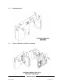
1
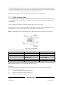
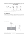
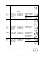
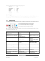
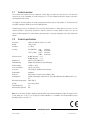
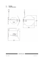
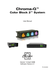
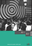
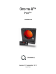
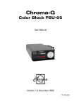
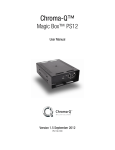
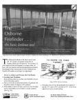
Chroma-Q™
Mirror
User Manual
Version 1.3 September 2012
PN: 123-0500
Warranty Statement
Chroma-Q warrants to the original purchaser, with proof of purchase, that its delivered products shall be free from defects in
material and workmanship under normal use for a period of 12 months from date of shipment.
Chroma-Q will repair, or at its option, provide an equivalent item or replace, the defective product during the stated warranty
period. This warranty applies only to the repair or replacement of the product and only when the product is properly handled,
installed and maintained according to Chroma-Q instructions. This warranty excludes defects resulting from improper
handling, storage, installation, acts of God, fire, vandalism or civil disturbances. Purchaser must notify Chroma-Q in writing
within 14 days of noticing the defect. This warranty excludes field labour or service charges related to the repair or
replacement of the product.
The warranty contained herein shall not extend to any finished goods or spare parts from which any serial number has been
removed or which have been damaged or rendered defective (a) as a result of normal wear and tear, willful or accidental
damage, negligence, misuse or abuse; (b) due to water or moisture, lightning, windstorm, abnormal voltage, harmonic
distortion, dust, dirt, corrosion or other external causes; (c) by operation outside the specifications contained in the user
documentation; (d) by the use of spare parts not manufactured or sold by Chroma-Q or by the connection or integration of
other equipment or software not approved by Chroma-Q unless the Customer provides acceptable proof to Chroma-Q that
the defect or damage was not caused by the above; (e) by modification, repair or service by anyone other than Chroma-Q,
who has not applied for and been approved by Chroma-Q to do such modification, repair or service unless the Customer
provides acceptable proof to Chroma-Q that the defect or damage was not caused by the above; (f) due to procedures,
deviating from procedures specified by Chroma-Q or (g) due to failure to store, install, test, commission, maintain, operate or
use finished goods and spare parts in a safe and reasonable manner and in accordance with Chroma-Q’s instructions (h) by
repair or replacement of engines without factory training.
The warranty contained herein shall not apply to finished goods or spare parts which are sold “as is”, as “second-hand”, as
used”, as “demo” or under similar qualifications or to Consumables (“Consumables” is defined as any part(s) of goods or
part(s) for use with goods, which part(s) of goods or part(s) for use with goods are consumed during the operation of the
goods and which part(s) of goods or part(s) for use with goods require replacement from time to time by a user such as, but
not limited to, light bulbs).
The warranty contained herein shall not apply, unless the total purchase price for the defective finished goods or spare parts
has been paid by the due date for payment.
The warranty contained herein applies only to the original purchaser and are not assignable or transferable to any
subsequent purchaser or end-user.
This warranty is subject to the shipment of the goods, within the warranty period, to the ChromaQ warranty returns
department, by the purchaser, at the purchasers expense. If no fault is found, ChromaQ will charge the purchaser for the
subsequent return of the goods.
Chroma-Q reserves the right to change the warranty period without prior notice and without incurring obligation and
expressly disclaims all warranties not stated in this limited warranty.
www.chroma-q.com
Mirror User Manual
1
V1.3 September 2012
Disclaimer
The information contained herein is offered in good faith and is believed to be accurate. However, because conditions and
methods of use of our products are beyond our control, this information should not be used in substitution for customer's
tests to ensure that Chroma-Q products are safe, effective, and fully satisfactory for the intended end use. Suggestions of
use shall not be taken as inducements to infringe any patent. Chroma-Q sole warranty is that the product will meet the sales
specifications in effect at the time of shipment. Your exclusive remedy for breach of such warranty is limited to refund of
purchase price or replacement of any product shown to be other than as warranted.
Chroma-Q reserves the right to change or make alteration to devices and their functionality without notice due to our on
going research and development.
The Chroma-Q Mirror has been designed specifically for the professional entertainment lighting industry. Regular
maintenance should be performed to ensure that the products perform well in the entertainment environment.
If you experience any difficulties with any Chroma-Q products please contact your selling dealer. If your selling dealer is
unable to help please contact [email protected]. If the selling dealer is unable to satisfy your servicing needs, please
contact the following, for full factory service:
Outside North America:
Tel: +44 (0)1494 446000
Fax: +44 (0)1494 461024
[email protected]
North America:
Tel: 416-255-9494
Fax: 416-255-3514
[email protected]
For further information please visit the Chroma-Q website at www.chroma-q.com.
Chroma-Q is a trademark, for more information on this visit www.chroma-q.com/trademarks.
The rights and ownership of all trademarks are recognised.
www.chroma-q.com
Mirror User Manual
2
V1.3 September 2012
Table of Contents
1.
Product Overview
……………...…………………………………………………….………... 4
2.
Operation
……………...…………………………………………………….………... 4
3.
2.1
Unpacking the units
…………………………………………………………. 4
2.2
Control and power cables
……………………………………………….…………. 5
2.3
Mounting the unit
…………………………………………………….……. 6
2.4
Operating the unit
…………………………………………………….……. 7
2.5
Modes of operation
………………………………………………………..… 7
2.6
Troubleshooting
2.7
Technical overview
2.8
Technical specifications ……………………………………………………………………11
Drawings
…………………………………………………………………… 10
………………………………………………… 11
……………...…………………………………………………….………... 12
3.1
Outside dimensions
…………………………………………………………. 12
3.2
Extension bracket
……………………………………………….…………. 13
3.3
Chroma-Q Broadway and Mirror combined …………………………………….…………. 13
www.chroma-q.com
Mirror User Manual
3
V1.3 September 2012
1.
Product overview
The Chroma-Q Mirror improves the functionality of a profile fixture by adding the remote capability of re-positioning the beam
of a single fixture in a fixed position to multiple varied locations. It is designed to give years of trouble free use, providing that
it is regularly maintained and used in accordance with the instructions detailed in this manual.
The Mirror is a motorised mirror attachment which mounts onto fixed position profile fixture to achieve many of the effects
traditionally only available with high priced intelligent moving lights. The compact and stylish design is equally at home in a
theatre, exhibition centre, shopping mall, or car showroom.
The moving mirror accurately redirects a fixed position beam of light through a pan of 230° and a tilt of 57°, making it a very
cost-effective and space-saving option for illuminating multiple locations using just a single profile fixture. As well as being
compatible with most standard medium and narrow beam profile fixtures, the unit can be daisy chained with Chroma-Q
colour changers and gobo rotators to provide moving colour and beam rotation effects.
The Chroma-Q Mirror is designed to operate either on the ANSI E1.11 USITT DMX 512-A protocol or in automatic mode. The
DMX serial data system allows for the individual addressing of multiple units on one data cabling system. The unit is
addressed by using the three push button switches and LED display. The unit equipped with a diagnostic section on the LED
display showing power, DMX signal and level presence.
When operating in automatic mode the Chroma-Q Mirror only requires a 24 VDC supply to operate.
Note: The quantity of Chroma-Q Mirror Mirrors used and the maximum cable length per power supply output is dependant
upon the size of PSU/splitter box used (see later in this manual for details).
2.
Section Name
2.1
Unpacking the unit
2.2
Control and power cables
2.3
Mounting the unit
2.4
Operating the unit
2.5
Modes of operation
2.6
Troubleshooting
2.7
Technical overview
2.8
Technical specifications
2.1
Unpacking the unit
The Chroma-Q Mirror package comes with the following items:
•
Chroma-Q Mirror
•
User manual
The unit is shipped in a specially constructed shipping carton to provide protection to the unit. Carefully open the carton and
remove the unit by grasping the support arm in the middle and lifting the unit vertically out of the carton. Next, carefully
remove the rubber restraint band used to stabilise the mirror unit during shipment.
www.chroma-q.com
Mirror User Manual
4
V1.3 September 2012
The front light shield had been designed so that it can act as a shipping support and must be repositioned before using the
unit. Loosen the two M4 wing screws on the front of the unit and reposition the light shield by moving the shield downward
to the position necessary to prevent light leaks depending on the beam angle and focusing.
Note: The packing material protects the fixture during shipment; always use it to transport the fixture.
2.2
Control and power cables
The Chroma-Q Mirror utilises an XLR 4-pin cable system to supply power and data. Pins 1 and 4 supply 24V DC power, pins
2 and 3 supply ANSI E1.11 USITT DMX 512-A control protocol and the connector shells should be connected via the
ground/drain wire.
For use in automatic mode the unit only requires a suitable 24V DC connected to pins 1 and 4).
Damage will occur if power connections short to data or ground/shield connections. When assembling XLR 4-pin cables,
heat shrink should be used on each individual pin to prevent short circuits (see diagram overleaf).
Note: It is very important to ensure that the drain wire from the cable shield is connected to both the XLR connector cases.
Detail of connector wiring (typical)
The correct wiring between male and female connectors is 'one to one'.
Pin #
Function
Minimum Cable size
1
Ground (-ve)
2.50mm² (14 AWG)
2
Control data minus (-)
0.35mm² (22 AWG)
3
Control data plus (+)
0.35mm² (22 AWG)
4
24V DC (+ve)
2.50mm² (14 AWG)
Chassis
Cable shield/drain wire
0.25mm² (24 AWG)
Note: Cable length should not exceed more than 60m /200' with return line.
Connections:
Correct connection of the units to the power supply will decrease the chances of units malfunctioning due to cabling
problems. Please follow these basic rules:
a)
Use the correct and gauge type of cable and connectors.
b)
Keep cable runs as short as possible to reduce line loss.
c)
Always use a return cable for each run.
www.chroma-q.com
Mirror User Manual
5
V1.3 September 2012
This will ensure balanced DC power to all units that the line is correctly terminated and all units receive power if one link of
the chain is faulty.
Note: Cable length should not exceed more than 60m (200') with return line.
2.3
Mounting the unit
For proper operation the unit must be firmly attached to the light fixture. To achieve this, the mounting plate of the unit has
two flat springs at the outer edge. The back plate should be inserted in the rear colour slot and gently pushed down until the
unit is firmly seated in the bottom of the slot. The safety wire supplied with the fixture should then be attached as a means of
secondary fixing.
Power and DMX should be brought to the unit by Tourflex Datasafe Ultra XLR-4 cable. If daisy chaining is desired, a XLR-4
cable should be run from the output connector on the unit to the next device in the chain.
When DMX is first applied to the unit it will go through a homing sequence which will cause the mirror to momentarily move
around.
Note: If the rear slot is not available for mounting of the unit because of the use of a gel holder in this slot, the front slot may
be used for mounting instead.
Chroma-Q Mirror mounted on a lighting fixture.
Note: Ensure the safety wire is used as a means of secondary attachment.
www.chroma-q.com
Mirror User Manual
6
V1.3 September 2012
2.4
Operating the unit
All unit functions are accessed using the LED display and the three push-button switches on the left side panel.
Control
Function
Red Button
Mode access and record
Black Button
Decreases (-) the mode level or value
Blue Button
Increases (+) the mode level or value
3 digit display
Displays mode, monitor or blank display
Push button operation:
The RED button is used to scroll through the different modes of operation and the BLUE or BLACK buttons used to select the
level or value in that mode. If any mode or value is changed, the last digit of the display will flash until the RED button is
pushed to acknowledge (or record) the change.
Display operation:
Power-up Display
On power-up, the display will show 'ini' during the initialisation sequence, and
then show the DMX address.
Monitor Display
The display will revert to 'Monitor Mode' if left undisturbed for 5-7 seconds.
The first vertical bar indicates that there is Power (24V DC).
The second vertical bar indicates that there is Data (DMX).
The horizontal bars indicate the data Signal Level (DMX).
See also: 'Troubleshooting' section of this manual.
Display Flip
The display can be flipped through 180º by pressing and holding the RED button then pressing the BLACK button.
2.5
Modes of operation
a. Effect (automatic) mode
In this mode the unit can be used without a DMX control signal; only a 24V DC supply is required.
To use the automatic mode;
•
Connect a suitable 24V DC power supply to the unit.
•
Press the RED button to scroll through the menu until the display reads 'At0'.
•
Press the BLUE button once, so that the display reads 'At1' (Auto mode) and press the RED button.
www.chroma-q.com
Mirror User Manual
7
V1.3 September 2012
•
Press the RED button to scroll through the menu until the display reads 'Pn'. This accesses the mirror panning
movement in the auto mode. Using the BLUE/BLACK buttons select the either range of movement you require Pn0
- Pn7, continuous back and forth sweep Pn8, or mirror held at the centre position Pn9. Press the RED button to
store the pan value and change the display to 'tL', the mirror tilting movement in the auto mode.
•
Repeat the above process to set a tilt movement value.
•
When the desired effect is selected, press the RED button.
b. DMX Control Mode
In this mode, the unit can be fully controlled using two or four DMX channels (see below). A combined DMX and 24V DC
supply cabling system is required in this system.
Press the RED button to move between modes, and to record any changes made.
DMX channel address mode
This mode is used to set the DMX start address in the range of 1-511 (2 channels, 8-bit resolution) and 1-509 (4 channels,
16-bit resolution).
The display shows the current DMX address.
(To alter the address, press BLUE or BLACK button once to increment/decrement the value; hold down the BLUE or BLACK
for fast increments/decrements of the value.)
Pan/tilt movement modes
These modes allow the user to reverse the direction of the pan, tilt, or pan and tilt motion, when the configurations of the
lighting fixture/mirror unit dictate.
The display shows either the pan movement or the tilt movement ('Pn' pan/ 'tL' tilt) and the current direction ('0'= normal/'1'
= reverse) of travel.
(Press BLUE or BLACK button to switch directions, and the RED button to change modes.)
DMX resolution
This mode is used to set the movement resolution, or accuracy, of the unit between two or four DMX control channels.
The display shows the current DMX mode ('rn0'= 8-bit or 'rn1'= 16-bit resolution).
(Press BLUE or BLACK to switch between modes.)
Display mode
This mode is used to switch the display on or off. This feature can be used to blank displays that may be an unwanted
distraction. The display will re-activate when any button is pressed.
The display shows the current display mode ('dP0'= display off or 'dP1'= display on),
(Press BLUE or BLACK to switch between on and off.)
DMX/Automatic Mode
This mode is used to select either DMX control or automatic (stand-alone) operation of the unit.
The display shows the current mode ('At0'= DMX control, or 'At1'= automatic mode).
(Press BLUE or BLACK to switch between modes.)
Summary of control functions:
Note: Press the RED button to move between modes, and to record any changes made.
www.chroma-q.com
Mirror User Manual
8
V1.3 September 2012
Mode
Description
Actions required
Display
DMX
Sets the units DMX
address.
To alter the address, press
BLUE or BLACK button once
to increase or decrease the
value; hold down the BLUE or
BLACK for fast increments or
decrements.
The display shows the current
DMX address.
This mode allows
the user to reverse
the direction of the
pan motion.
To alter the mode, press
BLUE or BLACK button once
to switch between modes.
The display shows that the PAN
movement is set for normal
direction.
This mode allows
the user to reverse
the direction of the
tilt motion.
To alter the mode, press
BLUE or BLACK button once
to switch between modes.
Sets unit operating
with 2 or 4 DMX
control channels,
with 8 or 16-bit
resolution.
To alter the mode, press
BLUE or BLACK button once
to switch between modes.
This mode is used to
switch the display on
or off.
To alter the mode, press
BLUE or BLACK button once
to switch between modes.
channel
address mode
Pan
movement
mode
Tilt
movement
mode
DMX
resolution
mode
Display mode
In the range of 1-511 (2
channel, 8-bit resolution)
In the range of 1-509 (4
channel, 16-bit resolution).
The display shows that the PAN
movement is set for reverse
direction.
The display shows that the TILT
movement is set for normal
direction.
The display shows that the TILT
movement is set for reverse
direction.
The display shows the unit is
set for 8-bit resolution.
The display shows the unit is
set for 16-bit resolution.
This shows that the display is
set for auto-blanking.
This shows that the display is
set to be permanently on.
DMX/
Automatic
mode
This mode allows
the user to select to
between DMX and
Automatic modes.
To alter the mode, press
BLUE or BLACK button once
to switch between modes.
The display shows that the unit
is set for DMX control.
The display shows that the unit
is set for automatic operation.
Default Settings:
'Factory' default settings
If the unit is reset, using the RED button (held down) and the BLUE button pressed for 2 sec's, the unit
will revert to the factory default settings.
www.chroma-q.com
Mirror User Manual
9
V1.3 September 2012
The 'Factory' default settings put the unit in its normal operating mode.
DMX Address
=
001
Pan/tilt direction
=
Normal
Resolution
=
8-bit
Display
=
On
DMX/Auto
=
DMX
Display Flip
=
Normal
'User' default settings
Each time the RED record button is pressed, the unit will save that change and these 'user defaults' will take precedence on
the next power cycle. These 'User' defaults can be reset to the 'factory' defaults using the method detailed above.
2.6
Troubleshooting
The LED display aids in the troubleshooting of the system. These indicators are located on the on the side panel of each unit.
The first vertical bar indicates that there is Power (24V DC).
The second vertical bar indicates that there is Data (DMX).
The horizontal bars indicate the data Signal Level (DMX).
Note: The signal level changes during normal operation of the unit and is present during automatic operation. 1st bar =
25%, 2nd bar = 50% and 3rd bar = 75%.
Symptom
Possible Cause
Solution
Unit does not respond to DMX control, but
display indicator is on.
Unit set to wrong or different DMX
address.
Check DMX address settings.
Unit doesn’t respond to DMX, DMX display
indicator is off.
Bad cable.
Check cable and DMX run from the
console.
Units run at different speeds.
Cable lengths are too long.
Check the cable length and
configuration.
No cable return line.
Ensure there is a cable return line
in the system.
Overloading of chain or cable runs
too long.
Check voltage levels on last unit.
Should not be below 20VDC.
Units have dim LED indicators and run slowly.
No DMX at splitter/PSU.
PSU overloaded.
Display indicators appear OK but unit does not
move.
Mechanical (or electrical) failure in
the unit.
Turn unit on and off. Return unit for
repair.
The tilt doesn't respond to DMX.
16-bit mode setting when 8-bit
control is intended, or vice versa.
Check and reset.
Mirror panning/tilting in opposite direction.
Pan/tilt reverse switch with improper
setting.
Check and reset.
The mirror vibrates in one place when it is
supposed to move.
Broken motor cable
Contact distributor for service
Popped out motor connector.
Reconnect and check.
www.chroma-q.com
Mirror User Manual
10
V1.3 September 2012
2.7
Technical overview
The electronics card consists of four key components: a motor driver (x 2), transceiver, and a processor. The transceiver
operates in the receive configuration to convert serial protocol to a TTL level. All data relevant to the operation of the unit is
stored onboard in flash memory.
The majority of electronics problems are usually created by external factors such as shorted cables etc. The transceivers are
susceptible to damage if 24VDC is present on the DMX signal lines.
Troubleshooting is a process of elimination. First, rule out the other field factors i.e. faulty cables, power sources etc. If an
electronics problem is suspected try replacing the electronics card first. If accuracy problems should occur, check for
obvious mechanical problems. For technical advice and/or parts please contact your selling dealer or the offices listed in this
manual.
2.8
Technical specifications
Dimensions:
260 x 228 x 266 mm / 10.25" x 9" x 10.5"
Weight:
1.6kg (3.5 lbs)
Resolution:
8 or 16 bit
Accuracy:
Pan (230º Max.)
Movement speed:
0.9º
0.028º
Tilt (57.3º Max.)
0.225º
0.028º
0-100% pan (max) = 2 sec
0-100% tilt (max) = 1 sec
8-bit mode
16-bit mode
8-bit mode
16-bit mode
DMX protocol:
ANSI E1.1 USITT DMX 512-A
DMX addressing:
Digitally, via push buttons (3) and LED display
Working Voltage:
24 VDC (+/- 10%)
Power consumption:
1PU (see note below)
Connectors:
XLR-4 (male) in and XLR-4 (female) through
Body material:
Aluminium
Body color:
Black powder coat (other colours available, P.O.A.)
Mounting plate:
Integral mounting plate, designed for use in any ellipsoidal fixture with a 160 mm (6.25") gel
slot
Max. ambient temperature:
40° C (104° F)
Cooling:
Convection (natural)
European approvals:
Yes
North American approvals:
N/A
Note: We use the Power Unit (PU) to simplify the load calculation on any given Chroma-Q power supply. For example a PSU12 will supply up to 12 PU, so you can plug-in 12 Chroma-Q Mirror or a combination of 6 Chroma-Q Mirrors and 6
Broadway scrollers on one PSU-12.
www.chroma-q.com
Mirror User Manual
11
V1.3 September 2012
3.
3.1
Drawings
Outside dimensions
www.chroma-q.com
Mirror User Manual
12
V1.3 September 2012
3.2
Extension bracket
3.3
Chroma-Q Broadway and Mirror combined
www.chroma-q.com
Mirror User Manual
13
V1.3 September 2012