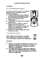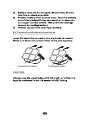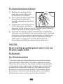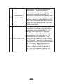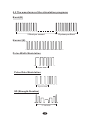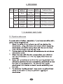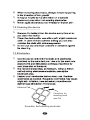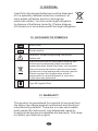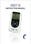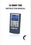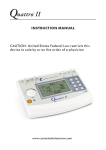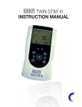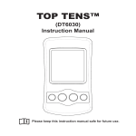
1
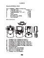
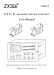
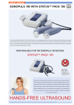
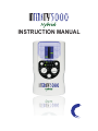
INSTRUCTION MANUAL
This manual is valid for the
TM
In TENSity 5000 TENS Stimulator
This user manual is published by Current Solutions™, LLC
Current Solutions™, LLC does not guarantee its contents and
reserves the right to improve and amend it at any time without
prior notice. Amendments may however be published in new
editions of this manual.
All Rights Reserved.Rev.V1.0 © 2011
: United States Federal Law restricts this device to sale by
or on the order of a physician or licensed practitioner
Conformity to safety standards
Current Solutions™, LLC declares that the device complies
with following normative documents:
IEC60601-1, IEC60601-1-2, I EC60601-2-10, IEC60601-1-4,
ISO10993-5, ISO10993-10, ISO10993-1
TABLE OF CONTENTS
1. INTRODUCTION...........................................................4
1.1 General
1.2 Medical background
2. PARTS......................................................................... 6
3. GENERAL WARNINGS AND SAFETY..............................8
4. INSTRUCTIONS FOR USE............................................ 11
4.1 Battery
4.2 Connect electrodes to lead wires
4.3 Connect lead wires to device
4.4 Electrode
4.5 Turn the device on:
4.6 Select the therapy mode:
4.7 Adjust the pulse width and pulse rate:
4.8 Select therapy time:
4.9 Adjust Channel intensity
4.10 Safety Lock Feature
4.11 Turn the device off
5. SPECIFICATION...........................................................17
5.1 Technical information:
5.2 The waveforms of the stimulation programs
6. Program....................................................................... 20
7. Cleaning and Care.........................................................20
7.1 Tips for skin care
7.2 Cleaning the device
7.3 Electrodes
7.4 Cleaning the Electrodes cords
7.5 Maintenance
8. TROUBLESHOOTING................................................... 24
9. MAINTENANCE AND CAUTIONS................................... 26
10. STORAGE.................................................................. 26
11. DISPOSAL..................................................................27
12. GLOSSARY OF SYMBOLS...........................................27
13. WARRANTY................................................................27
3
1. INTRODUCTION
1.1 General
TM
(anterior neck) or transcerebrally (through the head).
TM
1.2 Medical background
EXPLANATION OF PAIN
(anterior neck) or transcerebrally (through the head).
4
EXPLANATION OF TENS
(anterior neck) or transcerebrally (through the head).
HOW TENS WORK
(anterior neck) or transcerebrally (through the head).
5
2. PARTS
About InTENSity
TM
5000
TM
(anterior neck) or transcerebrally (through the head).
Main Unit Parts
15
1
16
2
3
5
4
6
17
7
8
9
10
11
12
13
19
14
18
(anterior neck) or transcerebrally (through the head).
6
(anterior neck) or transcerebrally (through the head).
7
3. GENERAL WARNINGS AND SAFETY
Before you start
(anterior neck) or transcerebrally (through the head).
Contraindications
Warnings
(anterior neck) or transcerebrally (through the head).
8
(anterior neck) or transcerebrally (through the head).
Precautions
(anterior neck) or transcerebrally (through the head).
9
(anterior neck) or transcerebrally (through the head).
Adverse Reactions
(anterior neck) or transcerebrally (through the head).
10
4. INSTRUCTIONS FOR USE
4.1 Battery
4.1.1 Check/Replace the battery
(anterior neck) or transcerebrally (through the head).
9V
6F22
4.1.2 Disposal of battery
CAUTION:
(anterior neck) or transcerebrally (through the head).
11
(anterior neck) or transcerebrally (through the head).
4.2 Connect electrodes to lead wires
Transparent Film
Connection Cables
CAUTION:
12
4.3 Connect lead wires to device
1) Before proceeding to this
step, be sure the device is
completely turned OFF.
2) Insert the wires provided with
the system into the jack
sockets located on top of the
device.
3) Holding the insulated portion
of the connector, push the
plug end of the wire into one of the jacks (see drawing);
one or two sets of wires may be used.
4) This device has two output receptacles controlled by
Channel 1 and Channel 2 at the top of the unit. You may
choose to use one channel with one pair of lead wires
or both channels with two pairs of lead wires. Using
both channels gives the user the advantage of
stimulating two different areas at the same time.
CAUTION:
4.4 Electrode
4.4.1 Electrode options
The electrodes are disposable and should be routinely
replaced when they start to lose their adhesive nature.
If you are unsure of your electrodes adhesive properties,
order replacement electrodes. Replacement electrodes
should be re-ordered through or on the advice of your
physician to ensure proper quality. Follow application
procedures outlined in electrode packing, to maintain
optimal stimulation and to prevent skin irritation.
13
4.4.2 Place electrode pads on skin
Apply electrodes to the exact site
indicated by your physician or
therapist. Before applying electrodes,
be sure the skin surface over which
electrodes are placed is thoroughly
clean and dry. Make sure the
electrodes are pressed firmly to the skin and make good
contact between the skin and the electrodes. Place the
electrodes over the skin; attach them properly, firmly, and
evenly.
CAUTION:
(anterior neck) or transcerebrally (through the head).
4.4.3 Electrode placement
The placement of electrodes can be one of the most
important parameters in achieving success with therapy.
Of utmost importance is the willingness of the physician to
try the various styles of electrode placement to find which
method best fits the needs of the individual patient.
14
Every patient responds to electrical stimulation differently
and their needs may vary from the conventional settings
suggested here. If the initial results are not positive, speak
to your physician about alternative stimulation settings
and/or electrode placements. Once an acceptable location
has been achieved, mark down the electrode sites and the
device settings, so the patient can easily continue treatment.
4.5 Turn the device on
In order to turn on the device, press [ON/OFF] button,
mode LED indicator and timer LED indicator will light up.
4.6 Select the therapy mode
(anterior neck) or transcerebrally (through the head).
4.7 Adjust the pulse width and pulse rate
By turning the [P. W.] knob clockwise to select pulse width,
the pulse width is adjustable from 30 us to 260 us.
By turning the [P. R.] knob clockwise to select pulse rate,
the pulse rate is adjustable from 2 Hz to 150 Hz.
4.8 Select therapy time
There are 4 therapy time (15, 30, 60, C) for you to select.
Press the [TIMER] button, the appropriate time LED
indicator will be light. Press [MODE] button cycle to select
the therapy time.
15
4.9 Adjust Channel intensity
Press the intensity control button [▲] and [▼] to control the
intensity output and you will hear a “beep” sound. Slowly
press the intensity button control until you reach the setting
recommended by your physician or therapist. Repeat for
the other channel, if both channels are used.
CAUTION:
1) The maximum output intensity level is 10.
2) The therapy mode and therapy time LED indicator
will flash in this state.
4.10 Safety Lock Feature
(anterior neck) or transcerebrally (through the head).
4.11 Turn the device off
16
5. SPECIFICATION
5.1 Technical information
Mechanism
01
Channel
02
Power Supply
Technical description
Dual, isolated between channels
One 9 Volt Battery
Adjustable,0-80 mA
03 Pulse Amplitude peak into 500 ohm load each channel
04
Pulse Rate
Adjustable, from 2 to 150 Hz
Burst rate: 0.5Hz (Burst mode)
05
Pulse Width
Adjustable,
from 30 to 260 microseconds
06
Voltage
0 to 40 V (Load : 500 ohm)
07
Wave Form
Mono-phase square pulse wave
08
Size
11.7cm(L) x 6.6cm(W) x 28.5cm(H)
09
Weight
10
Timer
11
Burst (B)
Bursts occur twice very second.Pulse
width(adjustable), pulse
rate = 100 Hz, Burst rate=0.5Hz
12
Normal Mode
(N)
The pulse rate and pulse width are
adjustable. It generates continuous
stimulation based on the setting value.
Modulation 1
mode (M1)
Modulation 1 mode is a pulse width
modulation. The pulse width is
automatically varied in a cycle
pattern over an interval of nominally
10 Seconds. Pulse width increase
over a period of 5 seconds from 30
us to the control setting value, then
decreases over a 5 seconds period
to its original value (30 us). The cycle
is then repeated.
13
94 g (without battery)
15, 30,60 minutes or Continue
17
14
15
Modulation 2
mode (M2)
Modulation 2 mode is a pulse rate
modulation. The pulse rate is
automatically varied in a cycle pattern
over an interval of nominally 10
Seconds. Pulse rate decreases over
a period of 5 seconds from the control
setting value to a value which is 40%
less, then increase over a 5 seconds
period to its original value. The cycle
is then repeated.
SD mode (SD)
The SD (Strength-Duration) mode
consists of automatic modulation
intensity and pulse width in 70%
range. The intensity is always
increasing while the pulse width is
decreasing and vice versa. The
intensity is decreased by 70%
while the pulse width is increased
by 70% in 5 seconds. In the next 5
seconds, the intensity is increased
by 70% while the pulse width is
decreased by 70%. Total cycle
time is 10 seconds. Pulse rate
(2~150Hz) and pulse width (30 ~
260μS) are fully adjustable.
18
5.2 The waveforms of the stimulation programs
Burst(B)
2 Burst per second
Normal (N)
Pulse Width Modulation
Cycle time
Pulse Rate Modulation
Cycle time
SD (Strength-Duration)
10 seconds
19
10 pulses per Burst
6. PROGRAM
Frequency Pulse
Mode Program Modulation
Method
Width
TENS
B
Burst
N
Continuous
Pulse width
modulation
Pulse rate
modulation
StrengthDuration
M1
M2
SD
Treatment time
100Hz
15,30,60min,continuous
Burst:0.5Hz 30-260us
2-150Hz 30-260us 15,30,60min,continuous
2-150Hz
30-260us 15,30,60min,continuous
2-150Hz
30-260us 15,30,60min,continuous
2-150Hz
30-260us 15,30,60min,continuous
7. CLEANING AND CARE
7.1 Tips for skin care
1)
2)
(anterior neck) or transcerebrally (through the head).
3)
4)
5)
20
6)
7)
8)
(anterior neck) or transcerebrally (through the head).
7.2 Cleaning the device
1)
2)
(anterior neck) or transcerebrally (through the head).
3)
7.3 Electrodes
1)
2)
(anterior neck) or transcerebrally (through the head).
3)
Adhesive Pad
Connector for
inserting Lead
wire Pin
Reusable, Self-adhering electrodes
21
To use these electrodes
1)
2)
3)
(anterior neck) or transcerebrally (through the head).
To remove your electrodes
1)
2)
(anterior neck) or transcerebrally (through the head).
3)
CAUTION:
1)
2)
3)
4)
(anterior neck) or transcerebrally (through the head).
5)
6)
7)
22
7.4 Cleaning the Electrodes cords
7.5 Maintenance
1)
2)
(anterior neck) or transcerebrally (through the head).
3)
4)
23
8. TROUBLESHOOTING
Problem
Possible Cause
Solution
1. Try fresh batteries.
LED indicator
fail to light up
Stimulation
weak or cannot
feel any
stimulation
Battery contact
failure
Electrodes
1. Dried out or
contaminated
2. Placement
2. Ensure batteries are
inserted correctly.
Check the following
contacts:
• All contacts are in place.
• All contacts are not broken.
Replace and
re-connect
Lead wires
Old/worn/damaged Replace
Intensity is too high Decrease intensity.
Stimulation is
uncomfortable
Electrodes are
too close together
Damaged or worn
electrodes or lead
wires
Electrode active
area size is too
small.
Mayn't operate the
device according
to the manual.
Reposition the electrodes.
Replace.
Replace electrodes with ones
that have an active area no
2
less than 16.0cm (4cm*4cm).
Please check the manual
before use.
1. Verify connection is
secure. Insure firmly.
Intermittent
output
2. Turn down the intensity.
Rotate lead wires in socket
90°. If still intermittent,
replace lead wire.
Lead wires
3. If still intermittent after
replacing lead wire, a
component may have failed.
Call the repair department.
24
4.Some programs will seem
intermittent. This is expected.
Improper electrode Reposition electrode
and applicator
Stimulation
and applicator
is ineffective. placement
Contact clinician.
Unknown
Use the electrodes Re-position the electrodes. If
on the same site
at any time you feel pain or
every time.
discomfort stop use
immediately.
The electrodes
Ensure the electrode is stuck
The skin
aren't stuck onto
securely on the skin.
becomes
the
skin
properly.
red and/or you
feel a stabbing The electrodes are Clean the electrode pads with
dirty.
pain
a damp, lint free cloth or
replace new electrode pads.
The surface of the
electrode was
scratched.
Replace new electrode.
The electrode pads Turn off the device and stick
come off the skin. the electrode pad firmly to
the skin.
Output current
The cable is
stops during
disconnected
therapy
The power of the
batteries has been
exhausted.
25
Turn off the device and
connect the cable
Please replace them with new
batteries.
9. MAINTENANCE AND CAUTIONS
1) Do not immerse device in water or any liquid. Do not
drop the device or throw it from a height.
2) After using the device, please remove the output plug
from the output socket and re-attach the electrode
pads to the protective transparent film.
3) Always use the protective film when the pads are not
in use.
4) Do not twist or pull the output cable.
5) Do not use any chemical to clean the main unit or the
electrodes. If you need to clean them, please wipe with
a damp, lint free cloth.
6) Do not let the pad dry out or expose to sunlight.
7) Keep the electrode pad clean.
10. STORAGE
1) Remove the batteries from the unit if you are not going
to use it for a long period of time.
2) Leaking batteries can damage the unit.
3) Do not make any sharp kinks in the connecting leads
or electrodes.
4) After use, stick the electrode pad onto the protective
plastic film.
5) Do not expose the device to direct sunlight and protect
it against dirt and moisture.
6) Store the device in a cool, well- ventilated place.
7) Never place any heavy objects on the device.
26
11. DISPOSAL
Used fully discharged batteries must be disposed
of in a specially labeled collection container, at
toxic waste collection points or through an
electrical retailer. You are under legal obligation
to dispose of batteries correctly. Please dispose
of the device in accordance with the legal obligation.
12. GLOSSARY OF SYMBOLS
Batch code
Serial number
Attention: Read the operating instruction
before use!
Electrical devices are recyclable material and
should not be disposed of with household
waste after their useful life! Help us to protect
the environment and save resources and take
this device to the appropriate collection points.
Please contact the organization which is
responsible for waste disposal in your area
if you have any questions.
Ty pe BF Applied Part
13. WARRANTY
This product is guaranteed for a period of one year from
the date of purchase against mechanical and electrical
manufacturing defects. There are no user serviceable
parts inside the instrument. Any attempted repair by
unauthorized persons invalidates the warranty. This does
not affect your statutory rights.
27
Manufactured for:
Current Solutions LLC
3814 Woodbury Drive
Austin,TX 78704
Ph:(800)871-7858
www.currentsolutionsnow.com
TM