1
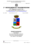
Invacare® ScanBeta NG
Child cot
User manual
Brugsanvisning
Bruksanvisning
Brugsvejledning
Manuel d’utilisation
Gebruiksaanwijzing
EN
DA
SV
NO
FR
NL
This manual must be given to the user of the product.
Before using this product, read this manual and save for future reference
Forside_ScanBeta.indd 1
2011-10-18 11:53:37
1
UM_1542073_UK_DA_ver01.indd 1
2011-10-18 10:00:51
Contents
1. General information . . . . . . . . . . . . . . . . . . . . . . . . . . . . . . . . . . . . . . . . . . . 4
1.1 Using the product . . . . . . . . . . . . . . . . . . . . . . . . . . . . . . . . . . . . . . . . . 4
1.2 Certification and requirements. . . . . . . . . . . . . . . . . . . . . . . . . . . . . . . 5
1.3 Explanation of labels and symbols . . . . . . . . . . . . . . . . . . . . . . . . . . . . 6
1.4 Safety instructions and warnings. . . . . . . . . . . . . . . . . . . . . . . . . . . . . . 7
2. On delivery. . . . . . . . . . . . . . . . . . . . . . . . . . . . . . . . . . . . . . . . . . . . . . . . . . . 9
2.1 Parts of the cot. . . . . . . . . . . . . . . . . . . . . . . . . . . . . . . . . . . . . . . . . . . . 9
2.2 Assembly the cot.. . . . . . . . . . . . . . . . . . . . . . . . . . . . . . . . . . . . . . . . . .10
3. Operating the cot . . . . . . . . . . . . . . . . . . . . . . . . . . . . . . . . . . . . . . . . . . . . .15
3.1 Using the hand control. . . . . . . . . . . . . . . . . . . . . . . . . . . . . . . . . . . . . .15
3.2 Operating the braking castors . . . . . . . . . . . . . . . . . . . . . . . . . . . . . . .16
3.3 Operation of the manual adjustments . . . . . . . . . . . . . . . . . . . . . . . . .17
4. Operating of accessories . . . . . . . . . . . . . . . . . . . . . . . . . . . . . . . . . . . . . . .18
4.1 Operating of downward-slideable side. . . . . . . . . . . . . . . . . . . . . . . . .18
4.2 Operation of side doors. . . . . . . . . . . . . . . . . . . . . . . . . . . . . . . . . . . . .19
5. Assembling and disassembling the cot . . . . . . . . . . . . . . . . . . . . . . . . . . . .20
5.1 Assembly of mattress support . . . . . . . . . . . . . . . . . . . . . . . . . . . . . . .20
5.2 Mounting of the pipe pin between shear arm and base . . . . . . . . . . .20
5.3 Removing the mattress support . . . . . . . . . . . . . . . . . . . . . . . . . . . . . .21
5.4 Mounting and removal of motors . . . . . . . . . . . . . . . . . . . . . . . . . . . . .21
2
UM_1542073_UK_DA_ver01.indd 2
2011-10-18 10:00:51
6. Cleaning and maintenance . . . . . . . . . . . . . . . . . . . . . . . . . . . . . . . . . . . . . .23
6.1 Cleaning . . . . . . . . . . . . . . . . . . . . . . . . . . . . . . . . . . . . . . . . . . . . . . . . .23
6.2 Maintenance . . . . . . . . . . . . . . . . . . . . . . . . . . . . . . . . . . . . . . . . . . . . . .23
6.3 Maintenance chart . . . . . . . . . . . . . . . . . . . . . . . . . . . . . . . . . . . . . . . . .24
7. Trouble-shooting the electrical system. . . . . . . . . . . . . . . . . . . . . . . . . . . .25
8. Electrical data . . . . . . . . . . . . . . . . . . . . . . . . . . . . . . . . . . . . . . . . . . . . . . . .26
9. Technical specifications . . . . . . . . . . . . . . . . . . . . . . . . . . . . . . . . . . . . . . . .27
9.1 Dimensions . . . . . . . . . . . . . . . . . . . . . . . . . . . . . . . . . . . . . . . . . . . . . . .27
9.2 Weights . . . . . . . . . . . . . . . . . . . . . . . . . . . . . . . . . . . . . . . . . . . . . . . . . .28
9.3 Transportation and storage conditions . . . . . . . . . . . . . . . . . . . . . . . .28
10. Disposal . . . . . . . . . . . . . . . . . . . . . . . . . . . . . . . . . . . . . . . . . . . . . . . . . . . .28
3
UM_1542073_UK_DA_ver01.indd 3
2011-10-18 10:00:52
Foreword
Congratulations with your choice of the Invacare®ScanBeta NG cot.
x
x
x
x
The total load on the ScanBeta NG cot should not exceed 100 kg. (SWL = Patient + mattress + sides
Patient max. weight
+ other equipment).
The ScanBeta NG cot is designed for patients requiring residential or home care nursing, in hospitals
and other healthcare institutions.
The ScanBeta NG cot combines stability with ergonomic design, making it easy to disassemble and
= 100 kg
operate.
The ScanBeta NG cot must only be used in accordance with this user manual and safety instructions.
Please read the entire user manual before using the cot.
You are welcome to contact Invacare®with any questions regarding the use or maintenance of the cot.
All instructions regarding left and right assume a patient is lying in the cot.
Please note that there may be sections of this user manual, that are not relevant for your cot, as the manual
is applicable (at the time of publication) for all existing models.
1. General information
1.1 Intended use
The ScanBeta NG cot has been designed for patients with limited mobility and for use in home care,
hospitals and other healthcare institutions.
Max. load (SWL)
The ScanBeta NG cot should only be used by patients whose body weight does not exceed 70 kg.
The ScanBeta NG cot can be adjusted to give the patient good ergonomics and the carer a good
working position.
= 70 kg
Depending on the model, the backrest, leg and thigh section or the whole mattress support can be adjusted
using either the hand control or manually.
4
UM_1542073_UK_DA_ver01.indd 4
2011-10-18 10:01:11
1.2 Certification and requirements
Invacare® is certified according to DS/EN ISO 9001 and ISO 13485.
This ensures the customers, that the product is always supplied in a uniform quality.
Throughout the entire production process the materials and products are quality controlled by the operators.
Once the product is assembled, a final test is carried out. The operator performing the test, which also includes checking all moving
parts, motors and castors, signs the receipt for the product with his/her personal QA-number.
If the product does not meet Invacare® stipulated quality requirements, the product will be rejected.
If, contrary to our expectations, there should be any problem with the product, please contact your local Invacare® supplier.
The ScanBeta NG cot is CE-marked in accordance with Directive 93/42/EEC on medical equipment.
The ScanBeta NG cot has undergone risk assessment in accordance with EN ISO14971:2008.
The ScanBeta NG cot has been approved in accordance with the Nordic Requirement Specification.
The ScanBeta NG cot has been approved in accordance with EN 60601:1996-03 and EN60601-1-2.
5
UM_1542073_UK_DA_ver01.indd 5
2011-10-18 10:01:11
1.3 Explanation of labels and symbols
WARNING - This symbol indicates danger.
If the necessary precautions are not taken, it may result in personal injury or damage to the cot.
NOTE - This symbol indicates important information and instructions.
Instruction - Reference to the user manual.
To identify the cot, see product-label on the base.
Electrical information
See chapter 7
Type no. of the bed.
Serial no.
Date of production.
Symbols
See chapter 1 and 8
Disposal
See chapter 10
6
UM_1542073_UK_DA_ver01.indd 6
2011-10-18 10:01:25
1.4 Safety instructions and warnings
Before using the cot, always check the following:
That the total load on the cot does not exceed 100 kg.
That the cot is not damaged or does not function correctly for any reason.
That the accessories for the cot are correctly fitted.
Invacare® does not accept any responsibility if used incorrectly, modified or assembled in any way other than described in the user manual. ONLY use approved accessories as stated in this user manual. Accesories that are not
approved by Invacare® may not be used on the cot.
If the cot is damaged on delivery, it must not be used until the damage is rectified.
See delivery conditions.
The cot must not be used for patients over 12 years of age or by patients whose body size is the same as, or larger
than, an average 12-year-old.
There is a risk that a patient might slip through the openings at the end of the cot. This may result in the patient
becoming trapped or asphyxiated between the mattress support, bed sides and bed end plate.
When the cot is raised or lowered there may be a risk of the patient becoming trapped in between the moveable
parts and mattress support.
Before adjusting the height, backrest, leg or thigh sections, the user must ensure that there are no blockages or
persons close by that may hinder the movement of the cot.
7
UM_1542073_UK_DA_ver01.indd 7
2011-10-18 10:01:44
It is recommended that the hand control is locked after each use.
Children must not play with the hand control.
If the hand control is used in an unauthorised way, there may be a risk
that persons, especially children, may get trapped in or under the cot.
The patient must not use the hand control without prior assessment by care personnel
The mains cable must be kept clear of all moveable parts.
Pull the plug out of the wall socket before moving the cot.
The cables must be fitted so that they do not touch the floor or block the castors.
When the bed is not being used, the mains cable must be removed from the wall socket.
Due to the formation of condensation, the cot must not be used until it has reached a temperature of over 10°C.
8
UM_1542073_UK_DA_ver01.indd 8
2011-10-18 10:01:52
2. On delivery
Bed end attachments
2.1 Parts of the cot
The cots top frame and
mattress support
Check that the packaging/cot has not been damaged and that all parts
are included. See illustration
There are several types of bed sides, and a cot may have the same
type on both sides or have different types on each side.
The bed end attachments and bed end plates should always be
mounted on the cot in both ends.
There may be a difference between your product and the illustration,
depending on which model and extra equipment you have chosen.
Downward-slideable side
Fixed side
* The bed sides may be of plexi glass or laminate instead of wood. All
illustrations in this user manual are shown wooden.
Bed end plate
Side doors*
Folding side doors*
9
UM_1542073_UK_DA_ver01.indd 9
2011-10-18 10:01:58
2.2 Assembling the cot
Be aware! Some parts of the cot are heavy. Always lift correctly.
Always leave the cot in the lowest position. This is the safest position should a patient fall out of the cot.
Do not climb under the cot.
2.2.1 Fitting the bed end attachments
2
1.
Place the two bed end attachments in the side frame tubes.
2.
Tighten the 2 x screws in each corner using the hexagonal key,
which is attached to the base frame.
3.
1
3
The bed end attachments should be aligned.
1
10
UM_1542073_UK_DA_ver01.indd 10
2011-10-18 10:02:15
2.2.2 Mounting the bed end plates
3
1.
Lift the bed end plate so that the guide pins in the top frame fit
into the holes on the lower edge of the bed end plate.
2.
Swing the upper edge of the bed end plate in towards the top
of the bed end pieces so that the holes in the top of the cot end
plate are flush with the holes in the bed end piece.
3.
Secure the cot end plate using the 2 screws provided.
4.
Repeat steps 1-3 for the opposite bed end plate.
5.
Please ensure that the bed end plate is securely mounted and
tightened.
2
1
2.2.3 Mounting the fixed bed sides
3
1.
Place the fixed bed side so that the guide pins in the side frame
tube can be guided into the brass bush on the bottom of the
lattice.
2.
Swing the upper edge of the fixed bed side in towards the bed
end piece, so that the holes in the brass bush are flush with the
holes and the guide pin fits.
3.
Secure the fixed bed side using the two screws provided.
4.
Please ensure that the fixed bed side is securely mounted and
tightened.
11
1
UM_1542073_UK_DA_ver01.indd 11
2011-10-18 10:02:20
2.2.4 Mounting the downward-slideable side
1
1.
Mount the wooden post to the corner posts and mount the
wooden rail on the side frame tube with the included screws.
NOTE! The slots must face in towards each other.
2.
Activate the locking pins on each side of the cot side.
1
3.
Guide the plastic rail on the downward-slideable side up from
below and into the slot on the wooden post.
4.
Lift the downward-slideable side up with both hands until the
locking pin clicks into place in the hole on the wooden post.
5.
Please ensure that both locking pins are secure by lifting the
downward-slideable side lightly up and down
2
2
3
3
12
UM_1542073_UK_DA_ver01.indd 12
2011-10-18 10:02:23
2.2.5 Mounting the side doors
3
1.
2.
3.
4.
5.
Place the door so that the guide pin in the side tube is fitted into
the brass bush on the bottom of the doors. To facilitate this,
make sure that the bed end pieces are aligned.
Swing the upper edge of the door towards the bed end piece,
so that the brass bush and the guide pin fits with the hole in the
corner mounting on top of the corner post.
Secure the door using the screws provided
Repeat points 1-3 for the other side.
Please ensure that both doors are securely mounted and
tightened and that the doors can be opened and closed without
binding.
2.2.6 Mounting the folding side doors
1.
2.
3.
4.
Place the folding doors so that the guide pin in the top frame fit
into the brass bush on the bottom of the doors. To facilitate this,
make sure that the bed end pieces are aligned.
Swing the upper edge of the folding door in towards the bed end
piece, so that the holes in the brass bush on the upper edge fit
with the holes on top of the corner post.
Secure the side bars using the two screws provided.
Please ensure that the folding doors are securely mounted and
tightened and that the doors can be opened and closed without
binding.
3
1
13
UM_1542073_UK_DA_ver01.indd 13
2011-10-18 10:02:26
2.2.6 Mattresses
The following mattresses can be used
Cot sizes
Mattress sizes
Incontinence cover
Part No.
Cotton cover
Part No.
140x60
160x70
180x80
140x60
160x70
180x80
1514560
1514561
1514562
1547664
1547529
1547528
There must be a minimum 220 mm from the top of the
mattress to the top of the bed end plate.
2.2.7 Other accessories
Fitting and use of accessories can be found in manuals supplied with
the accessories
The following accessories are approved for use in ScanBeta NG cot.
Lifting pole
Padding
Support handle
14
UM_1542073_UK_DA_ver01.indd 14
2011-10-18 10:02:28
3. Operating the cot
3.1 Using the hand control.
UP/DOWN
The cot is equipped with a hand control that, depending on
the model, can have different functions.
Sitting position
- green button
Backrest
- yellow button
Thigh section
- grey button
Height adjustment
of the bed
- white button
The hand control is equipped with a key that locks the bed’s
functions.
When the cot is in the right position, lock all
functions to prevent unwanted movement of the
cot.
Key
Key for locking and unlocking the electrical functions
Insert the key below each button to respectively lock and unlock the
hand control functions.
15
UM_1542073_UK_DA_ver01.indd 15
2011-10-18 10:02:28
3.2 Operating the braking castors
In some instances, the castors can mark certain types of floor, e.g. untreated wooden floors. If in doubt, Invacare®
recommends that a suitable protective covering is laid between the castors and the floor.
2
3.2.1 Operating castors without a central braking system
When the cot is in the desired position, at least one castor at the
head end and one castor in the foot end must be locked.
1
1. Lock: Step on the outer part of the pedal.
2. Releasing: Step on the release pedal.
Do not attempt to release the brake with your fingers as they may
get caught.
1
2
3.2.2 Operating castors with central braking system
When the cot is in the desired position, the brakes must be applied.
1. Neutral: When the pedal is in the horizontal position, the
brakes are not activated and the cot can be moved.
2. Brake: Depress the pedal to activate the brake.
16
UM_1542073_UK_DA_ver01.indd 16
2011-10-18 10:02:29
3.3 Operation of the manual adjustments
- Angle setting:
1.
The angle of the leg section is adjusted by lifting the leg section
frame to the desired position.
2.
Lower the frame carefully until the rastofix mounting locks into
place.
- Horizontal setting:
1.
Lift the leg section until the rastofix mounting disengages.
2.
Lower the leg section carefully to the horizontal position.
17
UM_1542073_UK_DA_ver01.indd 17
2011-10-18 10:02:30
4. Operating of accessories
4.1 Operating of downward-slideable side.
There is a risk that the downward-slideable side may fall down, resulting in slight injury e.g. to the feet.
Keep a firm grip on the downward-slideable side during operation.
- Down
1.
2.
3.
Lift slightly and then release the locking pin on both sides.
Pull the downwards-slideable side carefully down with both
hands.
When the downwards-slideable side is in the lowest position,
the locking pins will click into place in the lowest holes in the
wooden post.
1
- Up
1.
2.
3.
4.
Release the locking pin on both sides.
Lift the downwards-slideable side carefully up with both hands.
When the downwards-slideable side is in the highest position,
the locking pins will click into place in the uppermost holes in
the wooden post.
Always check that both locking pins are correctly positioned in
the holes in the wooden posts.
- Demounting
1.
2.
3.
4.
Open the downward-slideable side.
Release the locking pins with both sides.
Lower the downward-slideable side carefully out of the slots.
18
The downward-slideable side is removed.
UM_1542073_UK_DA_ver01.indd 18
2011-10-18 10:02:35
4.2 Operation of side doors.
Be careful not to get fingers caught when opening and closing the doors.
KG
When the door is open, it must not be have weight put on it as the cot may tip
over. The maximum angle of opening is 90°.
Open
- Open
The child lock bracket is opened as follows:
1. Pull down on the locking pin at the top of the door.
2. Push the rail to one side.
3. Pull up the locking pins on the bottom of the doors.
(Folding doors have 2 locking pins on each door).
4. Open the doors.
Close
- Close
1.
2.
3.
4.
Pull the locking pin on both doors at the bottom of the door up.
Close the doors. Ensure that the locking pin fits the hole in the
side rail.
Push the rail to one side until the locking pin is located.
Please ensure that the doors are sefely and securely closed.
19
UM_1542073_UK_DA_ver01.indd 19
2011-10-18 10:02:40
5. Assembling and disassembling the cot
There must be at least two persons to assemble / disassemble the mattress support.
Be careful not to get fingers caught when assembling the cot.
5.1 Assembly of mattress support
1.
2.
3.
4.
5.
6.
Lift the mattress support up over the base.
Carefully lower the mattress support so that the gliding shoes slide
into the gliding rail on both sides of the base.
Carefully lower the foot end, so that the axle ends drop into the
spring lock.
Lock the spring lock by pulling the red button out and turning it 45°
anti-clockwise until it locks.
The motors may need to be mounted once again. (see section 5.3)
Please ensure that the cot is properly assembled and that both spring
locks are in place and locked.
45
0
5.2 Mounting of the pipe pin between shear arm and base
1.
2.
3.
The pipe pin must be mounted with the opening upwards and locked.
Make sure that the pipe pins are fully inserted through both holes of
the tubular section, and that the spring clip is fully engaged onto the
bed end of the pin prior to operating the lifting mechnism on the bed.
Check that all four plastic bushings are intact and located correctly
between shear arm/base and shear arm/top frame.
Do not pull the clamp part of the pipe pin during dismantling – the clamp may be deformed, thus being unable to lock
properly.
20
UM_1542073_UK_DA_ver01.indd 20
2011-10-18 10:02:45
5.3 Removing the mattress support
1.
Please ensure that the motors are removed, whether they are mounted directly on the mattress support, or between the
mattress and the base. These must be removed before the mattress support can be removed. (See Chapter 5.3 for removal of
motors).
2.
Release the two spring locks by pulling the red button completely out and turning it 45° clockwise.
3.
Lift the cot end closest to the snap spring locks.
4.
Pull the mattress support backwards so that the gliding shoes can slide along the groove in the slide rails.
5.
Lift the mattress support at both ends.
Make sure that the castors are locked.
5.4 Mounting and removal of motors
Pull the mains cable out of the wall socket before removing the motor.
The cables must be fitted so that they cannot get caught in the cot’s moveable parts.
If the height adjustable motor is to be removed, there must be a minimum of two persons to hold the mattress support and one to remove the motor.
21
UM_1542073_UK_DA_ver01.indd 21
2011-10-18 10:03:00
If motors with integrated control units have to be removed / mounted, all cable connections to the other motors, as well as to the
hand control, must be removed / fitted.
All control units have a lock cam that must be loosened before the plugs can be pulled out of the control unit.
1.
2.
3.
Release the lock cam by pressing the small locking pins out with a screwdriver.
When mounting is complete, the lock cam must be fitted again.
Press down on the lock cam so the locking pins engage.
- Mounting the motor
1.
2.
3.
4.
5.
Place the motor in the fork mounts and pull the split pin through.
Lock the split pin.
Insert the plugs into the control unit. Take care that the plug is
the right way round and inserted correctly into the control unit.
Replace the lock cam.
Make sure that all the working parts function correctly.
- Removing the motor
When removing the height adjustable motor, the mattress support must be
held up by two persons.
1.
2.
3.
Remove the lock cam and pull the cables out of the control unit.
Open the split pins at both ends of the motor and pull them out.
The height adjustable motor can now be removed and the mattress support lowered
into the lowest position.
(On some models, the ends of the motor are secured by bolts and these must be removed).
22
UM_1542073_UK_DA_ver01.indd 22
2011-10-18 10:04:36
6. Cleaning and maintenance
6.1 Cleaning
Before cleaning the cot, ensure that the mains cable is removed from the wall socket.
The ScanBeta NG cot cannot withstand cleaning in washing machines or by high pressure water jets.
Clean with a soft wrung out cloth.
Use only neutral liquid cleaning fluids without solvents.
Cleaning of electrical parts must be done using a dry cloth.
6.2 Maintenance
Service and maintenance of the ScanBeta NG cot must only be carried out by personnel, who have undergone the
necessary training and instruction.
- Before use
Ensure that all manual and electrical parts function correctly and are safe to use.
- After 3 months use
Ensure that all manual and electrical parts and tighten all bolts, screws, nuts, etc.
- Annually
Service must be carried out in accordance with the service and maintenance chart.
See Chapter 6.3, “Maintenance chart”.
23
UM_1542073_UK_DA_ver01.indd 23
2011-10-18 10:04:45
6.3 Maintenance chart
Service and maintenance of the ScanBeta NG must only be carried out by personnel who have undergone the necessary
instruction or training.
Serial no. (placed on the cot base): _____________________
Date:
Initials:
Circlips, split pins and plastic fixing ring checked.
Screws, bolts and nuts tightened.
Weldings checked.
Castors brakes checked.
Height adjustment-, backrest- and leg-motor checked.
Cables correctly suspended and undamaged.
Plug undamaged.
Damaged coating repaired.
Wooden parts and doors checked
Accessories checked.
A service contract can be taken out in the countries where Invacare® has its own sales company.
Invacare® can also offer courses in the service and maintenance of the ScanBeta NG.
24
UM_1542073_UK_DA_ver01.indd 24
2011-10-18 10:04:46
7. Trouble-shooting the electrical system.
Make sure that the main cable is connected.
Defective cable
Sound from
the relay
No motor sound
Motor plug not
conneccted
Defective motor
Motor does
not run
No relay sound
Defective
control unit
Motor sound
Piston rod does
not move
Defective motor
25
UM_1542073_UK_DA_ver01.indd 25
2011-10-18 10:04:46
8. Electrical data
Voltage supply:
Max. current input:
Intermittent (periodic use of motors):
Max. accumulator capacity:
Protection class for motors:
Protection class for hand control:
Sound level:
230 V AC/50 Hz.
1 A.
10%, max. 6 minutes/hour.
1,2 Ah.
IP 66.
IP 54.
55 dB (A).
Double insulated, class II, type B:
Alternating current:
Direct current:
The patient is not separated from
the earth and the chassis:
The control unit has no circuit breaker. Disconnection from the mains is therefore the only means of switching off the power supply.
26
UM_1542073_UK_DA_ver01.indd 26
2011-10-18 10:04:54
9. Technical specifications
9.1 Dimensions
All measurements are given in mm. All measurements and angles are given without tolerances.
Invacare®reserves the right to change the stated measurements and angles without further notice.
b
c
d
e
f
62/72/82 cm
10 cm
30 - 85 cm
g
68/78/88 cm
a
L/W
a (mm)
b (mm)
c (mm)
d (mm)
e (mm)
f (mm)
g
h
h
60 cm
1480
1364
621,5
70
212
460,5
73°
36°
70 cm
1680
1564
671,5
150
222
520,5
73°
31°
80 cm
1880
1764
751,5
190
271,5
551
73°
27°
27
UM_1542073_UK_DA_ver01.indd 27
2011-10-18 10:05:09
9.2 Weights
Weight chart
Cot parts/size
70x160
Mattress support
31 kg
Base with shear
47 kg
Wooden bed end
13,5 kg
Cot total
91,5 kg
80x180
38 kg
47 kg
14,5 kg
99,5 kg
9.3 Transportation and storage conditions
Temperature between -10° and 50° C
Relative humidity between 10 and 80 % RH
Air pressure between 700 and 1.100 hPa
10. Disposal
This product has been supplied by an environmentally aware manufacturer in compliance with
the Waste Electrical and Electronic Equipment (WEEE) Directive 2002/96/CE.
This product may contain substances that could be harmful to the environment unless disposed of in
accordance (land fills) with current legislation.
The crossed out wheelie bin symbol is placed on this product to encourage you to recycle wherever possible.
Please be environmentally responsible and recycle this product through your local recycling facility at the end of its life.
28
UM_1542073_UK_DA_ver01.indd 28
2011-10-18 10:05:15