1
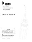
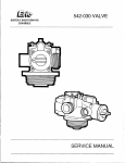
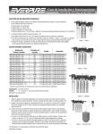
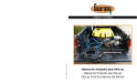
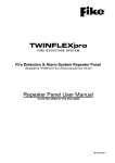
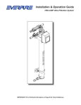
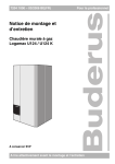
8.8601.00.4
EXPLOSION PROTECTION SYSTEM
HRD SUPPRESSION CONTAINER
INSTALLATION AND MAINTENANCE
INSTRUCTIONS
µ
8.8601.00.4
July, 2003
Explosion Protection Systems
HRD Suppression Container
Installation and Maintenance Instructions
REVISIONS
LETTER
2
3
4
DATE
02/01
02/2003
06/2003
BY
GB
JS
SM
DESCRIPTION
New Lay-out
General revision for Atex certification
§ 7.2 Periodic maintenance
TABLE OF CONTENTS
1
INTRODUCTION ........................................................................................................... 1
1.1
SCOPE .................................................................................................................................... 1
1.2
FIKE EXPLOSION SUPPRESSION CONCEPT ............................................................................. 1
1.3
DEFINITIONS .......................................................................................................................... 2
2
WARNINGS ..................................................................................................................... 4
3
HRD SUPPRESSION CONTAINER............................................................................. 5
4
3.1
DESCRIPTION ......................................................................................................................... 5
3.2
IDENTIFICATION OF SUPPRESSION CONTAINERS ................................................................... 5
HRD SUPPRESSION CONTAINER INSTALLATION ............................................. 9
4.1
MECHANICAL INSTALLATION ................................................................................................ 9
4.2
CONTAINER PRESSURISATION ................................................................................................ 9
4.3
ACTUATOR INSTALLATION & HANDLING ............................................................................. 10
5
HRD SUPPRESSION CONTAINER REFURBISHMENT....................................... 11
6
ACTUATOR INSTALLATION & HANDLING ........................................................ 13
7
6.1
ACTUATOR ASSEMBLY......................................................................................................... 13
6.2
PERSONAL SAFETY MEASURES ............................................................................................ 14
6.3
ELECTRICAL SAFETY PROCEDURES...................................................................................... 14
6.4
ACTUATOR INSTALLATION................................................................................................... 14
6.5
ACTUATOR EXCHANGE ........................................................................................................ 14
PERIODIC MAINTENANCE ...................................................................................... 15
7.1
GENERAL ............................................................................................................................. 15
7.2
PERIODIC INSPECTION:......................................................................................................... 16
7.3
THREE-MONTHLY SERVICE / INSPECTION BY FIKE: ............................................................. 16
7.4
THREE-YEARLY.................................................................................................................... 17
7.5
FIVE-YEARLY ....................................................................................................................... 17
7.6
TEN-YEARLY ........................................................................................................................ 17
8
DE-COMMISSIONING PROCEDURE / CHECK-LIST.......................................... 18
9
REPAIR AND RETURN AUTHORISATION............................................................ 19
Document 8.8601.00.4
Page i
FIGURES
FIGURE 1: SUPPRESSION CONTAINER TYPES ........................................................... 5
FIGURE 2: CONTAINER IDENTIFICATION PLATE (NAMEPLATE) ................................ 5
FIGURE 4: HRD SUPPRESSION CONTAINER (TYPICAL) ............................................ 7
FIGURE 5: SPREADER NOZZLES: STANDARD AND TELESCOPIC ................................ 8
FIGURE 7: SUPPRESSION CONTAINER FILLING PRESSURE......................................... 9
FIGURE 9: DETONATOR ASSEMBLY (TYPICAL)...................................................... 13
Document 8.8601.00.4
Page ii
1 INTRODUCTION
1.1
SCOPE
This document is intended to provide information and assist with the maintenance and repair of Fike
Europe 2.5 litre, 5 litre, 10 litre, 20 litre, 30 litre and 50 litre explosion suppression containers.
Individuals should read this manual carefully. Specific sections will be of particular interest
depending upon specific responsibilities. This information shall be used in conjunction with the
drawings and additional information provided for the specific application.
1.2
FIKE EXPLOSION SUPPRESSION CONCEPT
The risk of an industrial explosion occurs in many stages of production, transport, and storage of
combustible dusts and gases. Apart from all the known preventive measures to avoid conditions, in
which explosions may occur, a large number of constructive protection measures can be taken.
Protective techniques are classified into explosion venting, suppression and isolation. Explosion
venting and explosion suppression are designed to protect process vessels from over pressurisation.
Explosion isolation prevents explosions from spreading throughout a process. By isolating the
explosion, the effect of an explosion is limited to the equipment where the explosion initially
occurred.
Responsive explosion suppression systems act upon the detection of an explosion at its incipient
stage. These systems prevent pressure increase beyond a predetermined limit by instantaneously
discharging the suppressant powder, which chemically extinguishes the combustion reaction. To
suppress explosions the suppression system proceeds through 3 basic sequences: detection, initiation
and suppression.
Refer to Fike document 8.6501.00.x (Suppression Container HRD – Specifications and Installation
Instructions).
Document 8.8601.00.4
Page 1
1.3
DEFINITIONS
HRD-Suppressor (High Rate Discharge): Appliance containing an explosion suppressant that can
be expelled by the action of internal pressure.
Suppressant: Substance contained in the suppressor that, when dispersed into a volume to be
protected, can arrest or prevent a developing explosion in that volume. Three categories of
suppressants are in general use, separately or in combination (powder, water, halon-carbons).
Powder suppressant: Powder with recognised flame extinguishing properties such as products based
on mono-ammonium phosphate, potassium bicarbonate or sodium bicarbonate. Such suppressants
may contain additives to improve their flow properties and their effectiveness.
Actuator: Initiating device to open the HRD container, typically a gas generator (GCA or Gas
Cartridge Actuator) or detonator.
Explosion sensor: Device that is responsive to the changes of environmental parameters such as
pressure caused by a developing explosion.
Explosion detector: Device or arrangement of apparatus, containing one or more explosion sensors,
that responds to a developing explosion by providing an explosion detection signal.
Explosion: The propagating of a flame in a premixed dispersion of combustible gases dusts or
mixtures of these, in a gaseous oxidant such as air in a closed or substantially closed vessel.
Deflagration: Explosions which propagate because of heat transfer and having two distinctive and
separate parts - a pressure wave and a flame. The deflagration type of explosion is generally referred
to as a combustion reaction where the flame front burns into the unburned material at a velocity lower
than the speed of sound. The Fike hardware is designed to provide protection against deflagrations
only, not against detonations unless otherwise specified.
Dispersion nozzle: A discharge-device fitted on a Suppressor or the protected installation and
designed to deploy the suppressant into the equipment to be protected.
Control and indicating Equipment (CIE): Equipment which records and monitors the signals
transmitted by explosion pressure sensors / detectors spark and flame, temperature and other safety
sensors. Depending on configuration, by interrogation and interpretation of the detector / sensor data
the CIE selectively controls the actuation of Suppressors, extinguishing barriers, fast closing isolation
valves, process equipment shut down, water spray or extinguishant release, and all audible and visual
alarms. The CIE must be constructed according to special specifications.
Explosion Protection System Controller (EPSC): Fike equivalent name for CIE.
Zone: A zone that is protected against an explosion; it consists of protection devices that are
electrically linked with detectors. A validated (acknowledged) detection signal will activate the
explosion protection devices for that specific protected zone.
Document 8.8601.00.4
Page 2
Armed: the EPSC is active and will process a detection signal.
Disarmed: the EPSC is inactive and will not process a detection signal.
Shutdown: Disarm action followed by the dischargeing of the capacitors of a CIE/EPSC.
Consequently, the power to fire the actuator is no longer present. Therefore, shutdown is safer than
DISARM. Shutdown must be used during maintenance to an area of plant, where people can enter
the protected volume. Shutdown also guarantees a safe state of the circuitry for the operator or
technician for maintenance or measurements.
Fike Service Sign:
The sections marked with this icon require specialist assistance.
ONLY CERTIFIED FIELD SERVICE ENGINEERS SHALL PERFORM THE ACTIONS
DESCRIBED IN THESE MARKED SECTIONS.
Document 8.8601.00.4
Page 3
2 WARNINGS
WARNING: ALL MAINTENANCE WORK SHOULD BE EXECUTED BY CERTIFIED FIELD
SERVICE ENGINEERS.
ONLY COMPONENTS SUPPLIED BY FIKE i.e RELOAD KITS, SPARE PARTS
ETC., SHOULD BE USED TO REFURBISH THE CONTAINERS.
FIKE SHALL NOT BE LIABLE FOR CONSEQUENTIAL DAMAGES TO FIKE
ASSEMBLIES, COMPONENT PARTS OR HARM TO PERSONNEL IF WORK TO
THE FIKE EQUIPMENT IS CARRIED OUT BY NONE FIKE CERTIFIED
ENGINEERS.
THE SECTIONS MARKED WITH THIS ICON REQUIRE SPECIALIST
ASSISTANCE. PLEASE CONTACT FIKE FOR INFORMATION, ASSISTANCE OR
SERVICE TRAINING PROGRAMS.
WARNING: SUPPRESSION CONTAINERS ARE NOT DESIGNED TO BE EXPOSED TO
VIBRATIONS. FOR MORE DETAILS OR IN CASE OF DOUBT CONTACT FIKE.
WARNING: ONLY QUALIFIED FIKE PERSONNEL HAVE THE AUTHORITY TO INSTALL /
REMOVE ACTUATORS.
WARNING: IN MANY COUNTRIES THE TRANSPORT, STORAGE AND USE OF ACTUATORS
ARE CONTROLLED BY GOVERNMENT RULES AND OFFICES. THE LOCAL
AUTHORITIES MUST BE CONSULTED BEFORE TRANSPORT, USE OR
INSTALLATION OF THESE DEVICES AND THE RELEVANT PERMITS
OBTAINED
WARNING: ACTUATORS ARE PYROTECHNIC DEVICES THAT CAN CAUSE BODILY
INJURY AND / OR EQUIPMENT DAMAGE IF NOT HANDLED CORRECTLY.
ONLY AUTHORIZED PERSONS SHALL WORK WITH THESE DEVICES AND
MUST BE FAMILIAR WITH AND UNDERSTAND THE RELEVANT
PROCEDURES.
WARNING: TO PREVENT POSSIBLE INJURY, THE ACTUATOR MUST BE DISCONNECTED
AND SHUNTED WHENEVER PERFORMING ANY OF THE REFURBISHMENT
AND REBUILD PROCEDURES.
WARNING: IN NORMAL CIRCUMSTANCES, ACTUATORS ARE THE LAST PART TO BE
INSTALLED AND MAY ONLY BE INSTALLED WHEN EQUIPMENT AND
SYSTEM HAVE BEEN CHECKED.
Document 8.8601.00.4
Page 4
3 HRD SUPPRESSION CONTAINER
3.1
DESCRIPTION
The Fike explosion suppression containers, used in conjunction with other Fike explosion system
components, are designed to suppress explosions originating in vessels or prevent flame propagation
through ducts or conveying lines to downstream equipment or other operating locations.
Figure 1: Suppression container types
Fike Suppressant Containers are incorporated into the protection system to perform vital system
functions. The controlled and predictable release of the suppressant powder is a vital function.
Release of this media results from an electrical signal generated by the CIE or EPSC. The electrical
signal is transmitted to an actuator that instantly opens the rupture disc. Upon opening of the disc, the
suppressant powder flows out of the container. The rate and velocity of the discharging suppressant
powder are a function of the container outlet diameter, suppressant container geometry, initial
pressurisation level, temperature, flow path restrictions, and dispersion nozzle design.
3.2
IDENTIFICATION OF SUPPRESSION CONTAINERS
3.2.1
HRD-container: Nameplate
II 2/1 G/D
Ineris 03ATEX0058X
EExd IIC T6 IP66 T65°C
To identify the suppression container and order replacement parts, the containers have been
permanently labelled. The container identification plate, located on the cylindrical shell of the
container, contains among other things following information: Serial No, Gross Weight, Next
inspection date, Suppressant type, Suppressant Qty in Kg and Filling pressure (see Figure 2).
Figure 2: Container identification plate (nameplate)
Document 8.8601.00.4
Page 5
Document 8.8601.00.4
Page 6
3.2.2
HRD-container: Component parts
13
Figure 3: HRD suppression container (typical)
N°
Item description
N°
Item description
1
2
3
4
5
6
7
Pressure gauge
Fill valve
HRD suppressant container
Bracket for nameplate
Actuator boss
Electrical EExd junction box
Cable gland
8
9
10
11
12
13
14
15
Electrical shielded cable
Equipotential connection
Stud M27
Nut
Vessel wall, reinforcement plate
Process flange
Spreader nozzle, nozzle cover
Lifting lug
Table 1: Component parts
Document 8.8601.00.4
Page 7
3.2.3
HRD-containers: dimensions
Container type /
volume
(litre)
Max. dimensions
(mm)
A
2.5
5
10
20
30
50
Weight
empty
(Kg)
B
500
610
870
950
1160
1310
310
400
400
470
470
620
C
Thrust
(N)
D
430
470
470
470
470
628
∅ 114
∅ 168
Ø 168
Ø 273
Ø 273
Ø 273
30
42
46
75
85
150
8900
13345
22241
40034
44482
67000
Table 2: Dimensions (see details Figure 4)
3.2.4
HRD-containers: dispersion nozzles
Fike can supply 2 types of dispersion nozzle. The standard spreader nozzle assembly has a fixed
position in the vessel wall. The telescopic spreader nozzle on the other hand is stored outside of the
process vessel and is moved forward to protrude into the vessel when the system is activated.
Standard spreader nozzle
Telescopic spreader nozzle
Figure 4: Spreader nozzles: standard and telescopic
N°
Item description
N°
Item description
10
Stud M27
20
Holddown
11
Nut
21
Spreader nozzle cover telescopic
13
Process flange telescopic nozzle
22
Quad ring nozzle
14
Standard Spreader nozzle cover
23
Spreader nozzle telescopic
17
O-ring
24
Weldment telescopic
18
Rupture disc
25
Process flange
19
Cap-screws
26
Standard Spreader nozzle
Please consult the Fike relevant documents for a complete updated overview of nozzle configurations
(Fike doc. 8.6503.00.x).
Document 8.8601.00.4
Page 8
4 HRD SUPPRESSION CONTAINER INSTALLATION
WARNING: THE CONTAINER MUST BE INSTALLED BEFORE PRESSURISATION!
4.1
MECHANICAL INSTALLATION
Use the lifting lug (item 15, Figure 3) to manipulate the suppressant container.
The suppressant container requires sufficient structural support based on its weight and the dynamic
and static forces created during operation. Refer to Figure 4 and the Fike supplied Engineering
Drawings for the physical specifications of the suppressant container. The suppressant container must
be mounted to the process vessel using studs and nuts (Fike supply unless otherwise specified).
The nuts must be torqued to 81 Nm uniformly, in a criss cross pattern in one-third increments (26Nm
–53Nm – 81Nm) using a torque wrench.
4.2
CONTAINER PRESSURISATION
Fike suppressant containers are factory filled with suppressant powder. After installation, the
containers must be pressurised by a Fike Service Engineer during start-up of the system (dry nitrogen,
initial pressure 62 barg at 22°C). It is possible that the fill valve/gauge assembly is supplied in a
separate carton box, to prevent damages due to shipment. In this case, install the valve/gauge
assembly on the top mounted boss, after having removed the plastic protection cap. Make sure all
surfaces are clean and free from debris prior to installation. Use vacuum grease onto the O-ring and
groove, tighten untill the nut bottoms out. Refer to Figure 5 for the required filling pressure if the
ambient temperature differs from 22°C to prevent accidental firing and possible injury due to
overfilling.
Figure 5: Suppression container filling pressure
Document 8.8601.00.4
Page 9
To assure start-up, commissioning and fast reconditioning of the explosion protection devices, the
user should provide a stand-by filling station meeting the requirements as per Fike document
8.6605.00.x (Nitrogen filling requirements).
4.3
ACTUATOR INSTALLATION & HANDLING
Refer to SECTION 6 ACTUATOR INSTALLATION & HANDLING for details on installation of
the actuator.
Refer to the relevant CIE, EPSC manual and site specific drawing package for the completion of the
controller wiring and system checkout.
Document 8.8601.00.4
Page 10
5 HRD SUPPRESSION CONTAINER REFURBISHMENT
After an activation and the suppressant powder has been released, the container has to be refurbished.
The Fike HRD suppressant containers are designed to allow easy and quick on-site refurbishment.
When refurbishing an explosion suppression container, the following parts are required.
1. An explosion suppression reload kit which consists of:
an actuator boss and O-ring
a 4" or 6" disc assembly with O-ring
suppressant powder (SBC or Dessikarb)
2. Nozzle cover: standard or telescopic, in silicone (S) or metal (M);
3. Actuator (detonator or GCA) in safety enclosure.
WARNING: ONLY QUALIFIED FIKE PERSONNEL HAVE THE AUTHORITY TO INSTALL /
REMOVE ACTUATORS.
5.1.
Check on the container identification plate if the container is due for inspection or
testing.
WARNING: BEFORE STARTING ANY WORK, ENSURE THE PRESSURE GAUGE READS
ZERO.
WARNING: TO PREVENT POSSIBLE INJURY, NO ACTUATOR SHALL BE INSTALLED
WHEN PERFORMING ANY OF THE FOLLOWING ACTIONS.
5.2.
Remove the container from the process vessel. Make sure that only the nuts are
unscrewed while the studs remain inserted in the process flange. The studs will
ease container removal. First remove the lower nuts, leave the upper nut to be
unscrewed as the last of all to simplify container removal.
5.3.
Place the container in a horizontal position, be careful not to damage the gauge or
valve. Remove the outlet disc holddown flange from the container flange.
5.4.
Remove the opened rupture disc and O-ring.
WARNING: THE OPENED RUPTURE DISC IS VERY SHARP AND CAN CAUSE INJURY.
HANDLE WITH CARE!
5.5.
Clean the fill valve with pressurised air and make sure the valve seat is dirt free. In
case of doubt about the condition of the fill valve and/ or the gauge, a new gauge
and Valve pre-assembly must be installed (refer to the Fike suppression spare part
list).
Document 8.8601.00.4
Page 11
5.6.
Remove the jam nut to release the old actuator boss and o-ring. Clean the o-ring
seat and apply sufficient high vaccum grease (Dow Corning) on the o-ring and it’s
groove. Install a new actuator boss and o-ringboss. The junction box can be
removed to make the removal and installation of the actuator boss easier.
5.7.
Refill the container (still in horizontal position) with the correct type and quantity
of suppressant powder, using a funnel. When filling larger containers it is
necessary to incline the container slightly to prevent air becoming trapped in the
container.
5.8.
Clean the seat and install a new rupture disc and new O-ring. Apply sufficient high
vacuum grease (Dow corning) on the O-ring and its groove.
5.9.
Re-install the holddown on the rupture disc, lubricate the bolts (item 19) and
torque to 81 Nm uniformly in a criss-cross pattern in one-third increments (26 Nm
- 53 Nm - 81 Nm).
5.10.
Remove the opened spreader nozzle cover from the spreader nozzle assembly.
Apply a new cover on the spreader nozzle.
5.11.
When a telescopic spreader nozzle is used, clean all the moving (not painted) parts
and lubricate them with chassis grease. Inspect the condition of the quad-ring and
exchange if necessary. Install the quad-ring on the tip of the nozzle to ensure
optimal nozzle position.
5.12.
Mount the container and re-install the container washers & nuts, torque uniformly
in a criss-cross pattern in one-third increments increments (26Nm –53Nm – 81Nm)
using a torque wrench.
5.13.
Install a new actuator see SECTION 6.
5.14.
The container can now be pressurissed. Check the container identification plate for
the applicable fill pressure and pressurise with dry nitrogen (initial filling pressure:
62 barg at 22°C ambient temperature). Refer to Figure 5 for the required filling
pressure when the ambient temperature differs from 22°C. Check for leaks using a
suitable leak detection spray or liquid.
Document 8.8601.00.4
Page 12
6 ACTUATOR INSTALLATION & HANDLING
WARNING: ONLY QUALIFIED FIKE PERSONNEL HAVE THE AUTHORITY TO INSTALL /
REMOVE ACTUATORS.
The actuators of the Fike Explosion Protection Systems are widely used in industrial applications but
must be respected for their extremely fast response and the possibility of accidental detonation. When
actuators are handled in accordance with all proper safety practices, accidental detonations should not
occur.
WARNING: TO PREVENT POSSIBLE INJURY, THE ACTUATORS MUST BE DISCONNECTED
AND SHUNTED
PROCEDURES.
6.1
WHEN
PERFORMING
ANY
OF
THE
FOLLOWING
ACTUATOR ASSEMBLY
Each actuator is transported in a safety boss with two safety caps. In order to exchange an overdue
actuator, an additional, empty actuator transport boss is required to hold the overdue actuator.
WARNING: ACTUATORS
ARE INDIVIDUALLY LABELLED
IDENTIFICATION. DO NOT REMOVE THIS LABEL!
TO
ENABLE
PROPER
In the figure below a detonator in safety housing is shown (typical arrangement).
Figure 6: Detonator assembly (typical)
N°
Item description
N°
Item description
27
28
29
30
31
32
Original cap detonator wire
Shunted lead wires
Detonator tag
Cable length 1 m
Retainer nut
2 component epoxy glue
33
34
35
36
37
38
Pipe
Detonator
Jam nut
Safety cap
O-ring
Detonator boss
Document 8.8601.00.4
Page 13
6.2
PERSONAL SAFETY MEASURES
When handling actuators:
6.3
wear approved face protection;
do not wear static electricity producing clothing;
always put the safety cap on the actuator boss when removing it from the equipment.
Alternatively, actuator handling is also safe if the actuator is held into a safety transport
boss;
do not handle more than one actuator at the same time;
do not expose actuators to high heat sources as this may considerably affect their service
life.
ELECTRICAL SAFETY PROCEDURES
When handling actuators:
6.4
actuators must remain shunted at all times when electrically disconnected from the
protection system and during servicing;
do not check actuator continuity with any type of Ohm-meter or other measuring device;
do not install actuators if current is present on conduit or equipment;
do not install actuators if radio transmitters or wireless telephones are used in nearby
areas;
connect actuator lead wires only after the detonator assembly has been properly installed.
ACTUATOR INSTALLATION
ONLY QUALIFIED FIKE PERSONNEL HAVE THE AUTHORITY TO INSTALL
ACTUATORS.
6.5
ACTUATOR EXCHANGE
ONLY QUALIFIED FIKE PERSONNEL HAVE THE AUTHORITY TO REMOVE
ACTUATORS.
Refer to datasheet 8.6502.00 (Reload parts HRD) for further information and material listing.
Document 8.8601.00.4
Page 14
7 PERIODIC MAINTENANCE
CAUTION:
BEFORE MAINTENANCE OR SERVICE TO THE SYSTEM IS PERFORMED, MAKE SURE TO
BE FAMILIAR WITH THE SYSTEM OPERATION, INDIVIDUAL COMPONENT OPERATION,
AND SYSTEM SAFETY. THE PROTECTED PROCESS MUST BE IN A NON-HAZARDOUS
STATE.
7.1
GENERAL
In order to assure the SAFETY FUNCTION of the Fike protection system it is essential that the
integrity of the system remains. In order that your company can benefit from our after sales services
(in case of emergencies) a service contract should be set up prior to or just after commissioning. Once
the contract is in place you will receive our emergency (24 hour) telephone numbers.
Remarks:
1. We recommend that a service be carried out every 3 months.
2. Fike is unable to provide any additional support other than that stated in Fike’s standard conditions
of sale, unless a service contract is established.
The inspection schedule and procedure set forth below are provided as a minimum requirement for
Fike Explosion Protection Systems operating in moderate environments. If your particular protection
system does not employ all the equipment mentioned, disregard the appropriate instruction. The
instructions are to be implemented in conjunction with complete system inspection instructions.
During initial system checkout or start-up, the Fike Service Engineer may decide that - due to the
process characteristics - additional inspections are required. In such case, these are to be considered in
addition to the maintenance schedule given below.
It is extremely important to closely monitor the operational characteristics of your system during the
first few days or weeks after initial start-up.
Document 8.8601.00.4
Page 15
7.2
PERIODIC INSPECTION:
The following checks can be conducted by others than Fike. It is advised to conduct these checks at
regular intervals (once a week) and to file the results in a logbook. In this way, the Fike Service
Engineer will have a clear overview of the system status and behaviour during time. Furthermore, this
logbook will be very helpful for trouble shooting and system analysis upon system trouble conditions.
1. Before performing an inspection, it is important to obtain first all pertinent data related to the
specific system inspected. The information required includes and should be obtained from:
Fike System Engineered Drawings
Copy of manuals, specifications or documents referenced on Fike system drawings.
System owner’s operating procedures
Inspection equipment
Operating specifications of each component inspected.
2. Check the display of the CIE or EPSC:
in normal status, only the green LED’s on the front panel should be lit. Consult the
applicable EPSC user manual if this is not the case.
in normal status all programmed outputs should be switched active or armed. REFER TO
THE APPLICABLE EPSC USER MANUAL to perform any action on the explosion
controller.
3. Visually check all components for physical deterioration and abuse. If components’ ability to
perform is in question, they must be thoroughly tested and/or replaced. Do not submerge
components in liquids.
4. Check all components supporting hardware, mounting brackets, and bolts. Check if they are tight
and secure, replace if necessary.
5. Check the actual fill pressure of all pressurised components, top-up if necessary (Refer to § 4.2
Container Pressurisation).
6. File a complete and detailed report of the inspection findings with the system owner, servicing
company, and Fike.
7.3
THREE-MONTHLY SERVICE / INSPECTION BY FIKE:
A three-monthly inspection must be performed by a Fike Service Engineer or factory authorised
technicians. Consult Fike to schedule an inspection visit or for information on authorisation for
system service by others than Fike.
To perform an inspection, it is important to obtain first all pertinent data related to the specific system
inspected. The information required includes and should be obtained from:
Fike System Engineered Drawings
Copy of manuals, specifications or documents referenced on Fike system drawings.
System owner’s operating procedures
Inspection equipment
Operating specifications of each component inspected.
Document 8.8601.00.4
Page 16
During this 3-monthly inspection, the Fike Service Engineer (further on called SE) proceeds following
checks:
1. SE shuts down the Fike CIE or EPSC. SE then removes the actuators from the electrical circuit to
ensure the highest possible level of safety & security while working.
2. SE proceeds through a visual check of all components for physical deterioration and abuse. If
components’ ability to perform is in question, he will thoroughly test or even replace the specific
component(s).
3. SE checks all components supporting hardware, mounting brackets, and bolts to be tight and
secure.
4. SE checks the actual fill pressure of all pressurised components.
5. SE links a portable PC to the EPSC for a full-automatic system check. This software checks the
electronic addresses of the EPSC and the proper functioning of the controller.
6. SE also uses this Fike software to check whether all process equipment shutdown contacts controlled by the Fike system - operate in the appropriate sequence.
7. SE uses the Fike software for measureing the condition of the complete field wiring installation.
8. SE checks the explosion pressure detectors calibration for the activation pressure set point,
calibration adjusted as required.
9. SE to file a complete and detailed report of the inspection findings. A copy of this report will be
sent to the system owner or servicing company, Fike will retain a copy for their records.
7.4
THREE-YEARLY
1. A three-year inspection includes the replacement of all batteries, -EEPROMS.
7.5
FIVE-YEARLY
1. A five-year inspection includes the replacement of all detonators - actuators. Refer to the
applicable safety procedure.
2. National guidelines may require periodic testing of the suppression containers (pressure vessel
code). It is the responsibility of the owner to contact your local authorities having jurisdiction.
7.6
TEN-YEARLY
1. A ten-year inspection includes the replacement of all suppressant powder and GCA-actuators.
Refer to section 5 Refurbishment instructions.
NOTE:
The 3-, 5-, and 10-year replacements are based on a 60°C maximum service temperature. More
regular replacement may be necessary in case of higher temperatures or harsh operational
environments.
Document 8.8601.00.4
Page 17
8 DE-COMMISSIONING PROCEDURE / CHECK-LIST
The following procedure must only be performed by a Fike qualified Service Engineer, who has been
assigned to prepare and complete the de-commissioning of the above referenced Explosion Protection
System.
Each step in the listed procedure must be adhered to and completion/acceptance of this form is
mandatory. The Service Engineer must check off each of the following steps. In the case of noncompliance, the observed discrepancy must be corrected before completion of the system decommissioning.
STEPS / DESCRIPTION
1.
Use Fike system/project component location diagram to record
and verify the locations of all Fike system components for each
zone and system.
pass
fail
Remark/
Note No.
2.
Control Panel to be Disarmed/Shutdown.
pass
fail
Remark/
Note No.
3.
All Suppressor/Valve actuators to be shunted.
pass
fail
Remark/
Note No.
4.
Each Suppressor/Valve container to be depressurised. Note,
Do not ventilate Nitrogen in a confined space.
pass
fail
Remark/
Note No.
5.
Power supply to the Control Panel to be Isolated by the
Customer and disconnected to prevent accidental reconnection.
Fike to Verify.
pass
fail
Remark/
Note No.
6.
Control Panel battery to be disconnected and removed for
disposal.
pass
fail
Remark/
Note No.
7.
Each actuator is to be removed and placed in a storage boss, to
be either stored on site or removed for disposal.
pass
fail
Remark/
Note No.
8.
Verify that all Suppressor/valve gauges are reading zero,
replace fill valve cap loosely
pass
fail
Remark/
Note No.
ATTENTION: SYSTEM IS NOW DE-COMMISSIONED AND READY
FOR DISMOUNTING BY THE CUSTOMER/OWNER.
Document 8.8601.00.4
Page 18
9 REPAIR AND RETURN AUTHORISATION
Any component that is to be returned to Fike must be approved for return prior to shipment. In order
for the returned component to receive the correct attention * credit * repair * replacement * either
under warranty or at the owner's expense, an Material Return Authorisation number must be assigned
by Fike. A prearranged return authorisation will expedite the business and corrective action measures
taken upon receipt of the part(s).
A reference to the return authorisation number should be inserted to the packing slip. If a packing slip
is not used, then reference to the return authorisation number should be made through alternate
means. When preparing the component for shipment, please include your original Purchase Order
Number, Invoice Number, or Fike Production Order Number. Include with the package the address
you want the part shipped back to, shipment method, contact name, and telephone number.
A specific statement as the perceived defect or component failure will assist in examining the part(s).
This statement should also address symptoms and an operation history of the system in which the
component was installed.
In the event the suspect part is found within a larger top assembly component, the party assigning the
Material Return Authorisation Number (MRA) should be able to assist you as to whether the entire
assembly must be returned or only the component in question.
Return Address:
Fike Europe B.V.B.A.
Toekomstlaan 52
B-2200 Herentals
BELGIUM
tel. +32 14 21 00 31
fax +32 14 21 07 43
Attention:
Explosion Protection
MRA # __________
Document 8.8601.00.4
Page 19