1
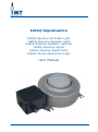
ILED® Signalisation
ILED® Aquarius Perimeter Light
ILED® Aquarius Repeater Light
ILED® Aquarius Repeater Light SA
ILED® Aquarius Signal
ILED® Aquarius Signal Flash
ILED® Taurus Obstruction Light
User Manual
User Manual
ILED® Signalisation
Contents
1.
2.
2.1
3.
3.1
3.2
4.
5.
5.1
5.2
6.
6.1
6.2
6.3
7.
7.1
7.2
8.
9.
10.
11.
Safety..................................................................................................................................... 3
Warranty ................................................................................................................................ 3
General.................................................................................................................................... 3
Type plate .............................................................................................................................. 4
Standard model ........................................................................................................................ 4
Explosion proof model ............................................................................................................... 5
Product Description................................................................................................................ 6
Specifications ......................................................................................................................... 6
General.................................................................................................................................... 6
Dimensions .............................................................................................................................. 6
Installation ............................................................................................................................ 7
Preparation .............................................................................................................................. 7
Assembly ................................................................................................................................. 7
Connections ............................................................................................................................. 8
Use ....................................................................................................................................... 10
Operation ................................................................................................................................10
Insulation test .........................................................................................................................10
Maintenance......................................................................................................................... 10
Recycling.............................................................................................................................. 10
Contact details ..................................................................................................................... 10
EC Declaration of Conformity ............................................................................................... 11
Copyright © IMT B.V.
All rights reserved.
No part of this User Manual may be copied, redistributed, published or changed without the prior written
permission of IMT B.V.
User Manual
ILED® Signalisation
2
Version 6.9 201302
User Manual
ILED® Signalisation
1. Safety
To ensure that the product is used safely and to optimize its useful life, the following instructions must be
observed.
Only qualified personnel may install the product.
Observe the locally applicable safety standards and safety regulations.
During assembling, make sure the light fitting is not subjected to mechanical stress.
If excessive tension is applied to the mounting feet during or after installation, such as when it is
mounted on an uneven surface, the mounting feet's spot welds can be broken off from the light fitting.
Use all the mounting holes when installing the light fitting.
Ensure that the cable gland used is suitable for the dimensions and type of cable to be connected.
This is necessary, otherwise the IP protection cannot be guaranteed.
Ensure that the cable gland used has an IP level of IP66, IP67 or IP68 in accordance with EN 60529,
and in case of an explosion proof lighting fixture, is Ex-e certified according to IEC 60079-7.
When using metal glands, use an earthing plate and lock nut on the inside of the junction box.
Ensure there is a reliable connection to the earthing system, both with the external earthing point
and with the connection in the light fitting junction box.
Never open the light fitting's housing.
Do not clean the light fitting using pressurized steam or a high-pressure water jet, to avoid
damage not covered by the warranty.
2. Warranty
2.1 General
The guarantee on the ILED® Signalisation series of fittings is only applicable when the light fitting is used
within the operational limits.
Operational limits are:
The minimum and maximum ambient temperature for the ILED® Signalisation fittings are -40° C and
+55°C
The light fitting must be installed by a qualified person and in compliance with the installation
instructions.
Damage caused by incorrect installation, accidents or external influences such as lighting strike and
harmonic distortion in accordance with EN 50055 are not covered by the guarantee.
The lighting level of the light fitting depends on the temperature and is therefore not covered by the guarantee.
If an ILED® Signalisation fittings fails within the warranty period, IMT B.V. will supply a new fitting with a
comparable specification free of charge. Before the guarantee can be confirmed, a defective light fitting must
be sent to IMT B.V. at the user’s expense for inspection. After this inspection the user will be informed of the
result(s). See invoice for individual guarantee agreements.
User Manual
ILED® Signalisation
3
Version 6.9 201302
User Manual
ILED® Signalisation
3. Type plate
3.1 Standard model
The standard light fitting has a type plate:
It contains the following information:
1.
Type
:
:
:
:
:
:
ILED®
ILED®
ILED®
ILED®
ILED®
ILED®
Aquarius Perimeter
Aquarius Repeater
Aquarius Repeater SA
Aquarius Signal
Aquarius Signal Flash
Taurus Obstruction
2.
Version
:
:
:
:
:
:
:
:
:
Green
Blue
Royal Blue
Red
Red Orange
Amber
Cool White
Neutral White
Warm White
3.
Ambient temp.
: -40°C up to 55°C
4.
Serial number
5.
Year of Manufacture
6.
Frequency
: 24Vdc
: Multi Voltage
geen
50/60
7.
Voltage
: 24Vdc
: Multi Voltage
24Vdc ±10%
95-255Vac of 130-360Vdc
8.
Current
: 24Vdc
: Multi Voltage
Max. 390mA
Max. 230-80mA of Max. 130-50mA
9.
Power
: 24Vdc
: Multi Voltage
Max. 10W
Max. 20W
/
/
/
/
/
/
/
/
/
Side
Side
Side
Side
Side
Side
Side
Side
Side
or
or
or
or
or
or
or
or
or
Flash
Flash
Flash
Flash
Flash
Flash
Flash
Flash
Flash
WARNING
The power and current are the maximum values. The precise values can be found
on the light fitting.
User Manual
ILED® Signalisation
4
Version 6.9 201302
User Manual
ILED® Signalisation
3.2 Explosion proof model
The explosion-proof model has a type plate:
It contains the following information:
1.
Type
:
:
:
:
:
:
ILED®
ILED®
ILED®
ILED®
ILED®
ILED®
2.
Version
:
:
:
:
:
:
:
:
:
Green
Blue
Royal Blue
Red
Red Orange
Amber
Cool White
Neutral White
Warm White
3.
Ambient temp.
: -40°C/+55°C
4.
Serial number
5.
Year of manufacture
6.
Frequency
: 24Vdc
: Multi Voltage
geen
50/60
7.
Voltage
: 24Vdc
: Multi Voltage
24Vdc ±10%
95-255Vac of 130-360Vdc
8.
Current
: 24Vdc
: Multi Voltage
Max.390mA
Max. 230-80mA of Max. 130-50mA
9.
Power
: 24Vdc
: Multi Voltage
Max. 10W
Max. 20W
10. Marking
Aquarius Perimeter
Aquarius Repeater
Aquarius Repeater SA
Aquarius Signal
Aquarius Signal Flash
Taurus Obstruction
: 24Vdc
: Multi Voltage
/
/
/
/
/
/
/
/
/
II
II
II
II
Side
Side
Side
Side
Side
Side
Side
Side
Side
2
2
2
2
G
D
G
D
Ex
Ex
Ex
Ex
or
or
or
or
or
or
or
or
or
Flash
Flash
Flash
Flash
Flash
Flash
Flash
Flash
Flash
e mb II T4
tD A21 IP66 T100°C
e mb II T4
tD A21 IP66 T100°C
WARNING
The power and current are the maximum values. The precise values can be found
on the light fitting.
User Manual
ILED® Signalisation
5
Version 6.9 201302
User Manual
ILED® Signalisation
4. Product Description
All ILED® Signalisation light fittings are designed for use in demanding surroundings.
The various ILED® Signalisation light fittings:
Have a 2-year warranty for correct operation
Are sealed for life
Are vibration-proof
Are based on ILED® technology
explosion-safe model ATEX category 2 suitable for use in Zone 1 & 211
5. Specifications
5.1 General
Housing
Lens
Colour
Mechanical protection
Voltage 24Vdc
Voltage Multi-Voltage
Burning position
(Re)ignition
Power factor
Connection
:
:
:
:
Stainless steel 316L (AISI)
Hardened glass
Perimeter Green, according to ICAO Annex 14 Vol. 1 Appendix 1
Obstruction and Repeater Light Red, according to ICAO Annex 14 Vol. 1
Appendix 1
: IP66
: 24 VDC ±10%
: 95-255Vac 50/60Hz / 130-360Vdc ( no Signal Flash and Repeater)
: Universal
: Immediate
: >0,55
: Fitted as standard with a junction box, type E012129, suitable for a singlephase connection.
Options
The following options are available for all the ILED® Signalisation light fittings:
Junction boxes in other sizes.
3-phase connection.
5.2 Dimensions
1
Risk of the presence of an explosive gas mixture or dust mixture during normal operation is high (10 to 1,000 hours per year)
User Manual
ILED® Signalisation
6
Version 6.9 201302
User Manual
ILED® Signalisation
6. Installation
6.1 Preparation
1.
Check whether the light fitting is to be installed in an environment that meets the ambient
temperatures, gas group and temperature class. This data is included on the light fitting type plate.
WARNING
Use the IMT ILED Repeater and Signal Flash only in combination with the IMT
control IM-RO-SYNC
WARNING
Installation of a light fitting in an environment that does not meet the specified
conditions may result in a dangerous situation.
WARNING
Installation of a light fitting in an environment that does not meet the specified
ambient temperatures may have a negative effect on the useful life of the light
fitting.
2.
Choose the correct type of protection for the light fitting. When doing so, ensure:
a. The choice of cut-out current for the safety device is suitable for the expected nominal current.
This depends on the number of light fittings that are connected.
b. The safety device's cut-out power is suitable for the maximum short-circuit current that the mains
power supply can provide.
c. The safety device for the 24 VDC version has a maximum cut-out current of 4 A.
6.2
1.
2.
Assembly
Remove the light fitting from the packaging.
Inspect the light fitting for mechanical damage.
WARNING
Installation of a light fitting in an environment that does not meet the specified
conditions may result in a dangerous situation.
WARNING
Installation of a light fitting in an environment that does not meet the specified
ambient temperatures may have a negative effect on the useful life of the light
fitting.
3.
Mount the light fitting to the construction.
Ensure there is a reliable connection to the earthing system, both with the external earthing point and
with the connection in the light fitting junction box.
Ensure that the cable gland is suitable for the dimensions of the type of cable that will be connected
and has an IP level of IP66, IP67 or IP68 in conformance with EN 60529, and in case of an explosion
proof lighting fixture, is Ex-e certified according to IEC 60079-7. This is necessary to ensure the IP
protection, and to be suitable for a hazardous environment.
WARNING
During assembly, make sure the light fitting is not subjected to mechanical stress.
4.
Route the connection cable correctly through the cable gland. Pay special attention to make sure
the cable gland is suitable for the dimensions and type of cable to be connected. This is necessary,
otherwise the IP protection cannot be guaranteed. An M20 cable gland is suitable for a cable diameter of
5.5 - 13 mm and an M25 cable gland is suitable for a cable diameter of 8 - 17 mm.
WARNING
If metal cable glands or blind plugs are used, an earthing plate must be used in the
junction box.
WARNING
If other cable glands or blind plugs are used, they must at least meet the
requirements of ATEX Ex II 2 G Ex e II in accordance with EN 60079-0:2006 and
EN 60079-7:2007 or meet the requirements of ATEX Ex II 2 D Ex tD A21 IP66 in
accordance with EN 61241-0 and EN 61241-1. Threaded holes in the junction box
are M20 x 1.5 or M25 x 1.5.
User Manual
ILED® Signalisation
7
Version 6.9 201302
User Manual
ILED® Signalisation
5.
6.
7.
8.
Cut the cable to the required length.
Connect the cable to the terminals. The standard terminals in the junction box are suitable as a
standard for a core diameter of 0.22 - 4 mm².
Check the connections that have been made.
Close the junction box
WARNING
The installation must be carried out in accordance with (NEN-EN)IEC 60079-14.
6.3 Connections
As standard, there is a terminal block in the junction box of the Perimeter and Obstruction Multi voltage version
which is suitable of a 1-phase connection as shown in the diagram.
Multi voltage version:
The following connection can be made:
L and N
Power connection
As standard, there is a terminal block in the junction box of the Perimeter, Obstruction 24 VDC version and the
Repeater Light SA version as shown in the diagram.
24 VDC version:
The following connection can be made:
+ and DC power connection
WARNING
Swapping over the + and – may damage the light fitting.
User Manual
ILED® Signalisation
8
Version 6.9 201302
User Manual
ILED® Signalisation
As standard, there is a terminal block in the junction box of the 24 Vdc Repeater Light version as shown in the
diagram.
24Vdc Repeater Light Version:
The following connection can be made:
+ and DC power connection
1 and 2
Connection for Control, Connect on 1 and 2 of IM-RO-SYNC
WARNING
Use the IMT ILED Repeater Light only in combination with the IMT control IMRO-SYNC
WARNING
Swapping over the + and – may damage the light fitting.
WARNING
Installing the 24V on the 1 and 2 will damage the light fitting.
WARNING
Connection 1 and 2 can not be used serial or parallel
User Manual
ILED® Signalisation
9
Version 6.9 201302
User Manual
ILED® Signalisation
7. Use
7.1 Operation
The light fitting can be used as soon as the installation has been completed.
7.2 Insulation test
Installations in which ILED® Signalisation light fittings are installed can be tested by means of an insulation
test. For this test, apply a maximum of 500 VDC between earth and phase or neutral wire.
WARNING
Never apply more than 500 VDC between a phase and a neutral wire.
All the light fittings are subjected to a dielectric test during manufacture (Perimeter, Obstruction and Repeater
Light) (24 VDC version: 700 VDC for 60 seconds, Perimeter and Obstruction Multi voltage version: 2115 VAC
for 60 seconds). In addition, the light fittings have also been subjected to an endurance test.
8. Maintenance
The light fittings are 'sealed for life' and, therefore, cannot be opened. Consequently, maintenance as stated in
IEC 60079-17 is not applicable; a visual inspection for correct operation is sufficient.
WARNING
Opening the light fitting invalidates any warranty claim.
9. Recycling
For recycling the light fitting, agreements have been made with local authorities within the context of the WEEE
directive.
Contact your local partner (see 'Contact details'). Your local partner will take care of further processing
10.
Contact details
IMT B.V.
Pascalweg 10a, 4104 BG Culemborg
P.O. Box 88, 4100 AB Culemborg
THE NETHERLANDS
Phone : +31 (0)88 – 12 69 100
Fax
: +31 (0)88 – 12 69 101
E-mail : [email protected]
For an up-to-date overview of all national and international contacts, visit our website: www.imt.eu.
User Manual
ILED® Signalisation
10
Version 6.9 201302
User Manual
ILED® Signalisation
11.
EC Declaration of Conformity
The undersigned, representing the company
IMT B.V.
Pascalweg 10a
4104 BG Culemborg
The Netherlands
Phone :+31 (0) 88 - 12 69 100
herewith declares that the product, ILED® Signalisation lighting, marked with Ex II 2 G Ex e mb II T4, Ex II
2 D Ex tD A21 IP66 T100° C, complies with the terms of the EC directive(s), including all applicable
supplements.
94/9/EC
Equipment and protective systems intended for use in potentially explosive atmospheres.
2004/108/EC
Electromagnetic Compatibility.
And with the provisions of the following standards and/or technical specifications.
Standard
Issue
Title
EN 60079-0
2006
Electrical apparatus for potentially explosive atmospheres
General requirements
EN 60079-7
2007
Explosive atmospheres – Part 7: Equipment protection by increased safety
“e”
EN 60079-18
2004
Explosive atmospheres – Part 18: Equipment protection by encapsulation
“m”
EN 61241-0
2006
Electrical apparatus for use in the presence of combustible dust. Part 0:
General Requirements.
EN 61241-1
2004
Electrical apparatus for use in the presence of combustible dust. Part 1:
Protection by enclosures “tD”
EN 61547
2009
Equipment for general lighting purposes. EMC immunity requirements
EN 61000-3-2
2006
Limits for harmonic current emissions (equipment input current up to and
including 16A per phase)
EC type certificate number KEMA 08 ATEX0158 X issued by
Kema B.V.
Utrechtseweg 310
6812 AR ARNHEM
Nederland
Identification number: 0344
Culemborg, 1-12-2010
IMT B.V.
R.L.L.M.G. Mignot , Managing director
User Manual
ILED® Signalisation
11
Version 6.9 201302
IMT B.V.
Pascalweg 10a, 4104 BG Culemborg
P.O. Box 88, 4100 AB Culemborg
Tel: +31 (0)88 – 12 69 100, Fax +31 (0) 88 – 12 69 101
www.imt.eu, [email protected]