1
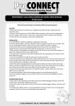
PIR Switch User Manual
Application:
Ideal for use in public buildings, stairwells, corridors, warehouses, toilet lobbies or
areas where lights only required when occupied. The PIR switch will allow lights or
fans to operate up to a point where no moving body heat is detected.
Suitable for fluorescent lights, incandescent lamps, energy save lamps or exhaust
fans.
Properties:
-
Reduce Energy Bills, Durable, Save and Reliable.
-
The PIR switch will continuous monitoring of human body heat changes, switch
on the connected load automatically when an area is occupied, and then switch
it off when the area has been vacant for a chosen duration.
-
Photocell included which only operate in dim light (adjustable)
-
In room temperature of 20°C, detection range is within 8 m, in higher temperate,
the detection distance may be reduced.
-
Switch ON the Manual Switch which will overwrite the PIR sensor and will turn
the light to an always on situation. Switch OFF the manual switch will keep the
light controlled by the PIR sensor.(if applicable)
Specification:
Fit standard 1 gang box, 25mm depth required.
Rating:
Max. 10A (2400W) for incandescent lamps
Max. 3A (720W) for energy save lamp, fluorescent lamp, fan
180~240Vac 50/60Hz
Time lag: 1 to 16 minutes (adjustable)
Coverage: 120° cone angle, within 5m distance
Standby power consumption: < 0.2W
Photocell range: 5 to 1000 lux (adjustable)
Wiring instruction:
1. Please connect with an 10A protective device.
2. Isolate mains supply from existing accessory by switching off at main fuse box.
3. Remove retaining screws and carefully withdraw accessory from wall box to
reveal connections at rear.
4. Check that no mains voltage is present within existing accessory by use of 240
volt test lamp (if available)
5. Disconnect all cables noting their respective connections.
6. Connect accessory with reference to the wiring diagram (3 wiring terminals).
5. Check all connections thoroughly.
6. Re-fit accessory in position, taking care not to trap any cables beneath plate
fixing screws.
7. Switch on mains supply at fuse box and check operation of accessory.
IF IN DOUBT CONSULT A QUALIFIED ELECTRICIAN.
.
Remark:
- The distance between the lamp and this switch should be greater than 0.5M.
- Do not overload (for fluorescent lights, energy save lamps and exhaust fan, total
load must not greater than 720W)
- During first installation, the light will flash 3 times and than switch off in day time
under sufficient light -- this is normal.
Wiring Diagram:
LIVE IN
LIVE OUT
NEUTRAL
LOAD