1
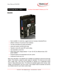
HIDDEN CAMERA DETECTOR
SEL SP-102 «АРКАМ»
Operation manual
Moscow
2013
1
CONTENT
1 Intended use and structure ………………………………………………………..
2 Delivery set …………………………………………………………
3 Basic technical specifications ………………………………….
4 Operating conditions……………………………………………………..
5 Construction and performance…………..……………………………………………
6 Safety instructions ………………………………………………..
7 Preparation for operation and operating a device ........................................
8 Content of precious materials and metals …………………….
9 Repairs……………………………………………………………………..
10 Transportation and storage ………………………………………….
11 Utilization ………………………………………………………………..
Warranty certificate ………………………………………………………
-3
-3
-3
-3
-4
-5
-5
-9
-9
-9
-10
-11
2
This operation manual is intended for explanation of an operation principle and application of a
hidden camera detector SEL SP-102 “АРКАМ” (hereinafter referred to as „The Device“).
1. INTENDED USE
The Device is designed for remote detection of hidden active, i.e. currently recording,
cameras in premises and items. The Device detects cameras regardless of their camouflage and way
of video transfer. The Device is able to detect both standard (wired) cameras and cameras
transmitting information through a radio channel.
Thus, unlike camera detectors working on the optical principle, the Device does not
need intent monotonous examination of all flat areas of premises, but allows detecting presence of a
hidden camera in a matter of seconds and then finding it.
Mini-USB connector ensures connection of the detector to a computer in order to
update software and a base of cameras known at the moment.
2. DELIVERY SET
1. SEL SP-102 “АРКАМ” device
2. Battery charger
3. Operation manual
4. Shipping package
3. BASIC TECHNICAL SPECIFICATIONS
Average camera detection range
Average camera detection time
Maximum detection time
Operating band
Detection indication
Continuous run time
Battery charging time
Antenna
Antenna directional pattern
Screen/display
Battery power
Operating temperature range
Dimensions
Weight
Up to 15 m
From 5 to 15 s
No more than 1 min.
100 – 500 MHz
Light indication
Up to 1 hour
About 1,5 hours
Cylindrical
Broad-band
Circular
Colour, 74 mm diagonal
Li-Ion battery
From -10ºC to +40ºC
125 x 80 x 35 mm
460 g
4. OPERATING CONDITIONS
4.1. The Device can be used in temperate conditions at an ambient air temperature ranging from
- 10ºC to 50ºC and relative air humidity up to 98% at a temperature of 20ºC.
4.2. After storage in a cold or wet room and also after transportation the Device should stay in
normal conditions at least 2 hours before switching it on.
4.3. There must be no dust, alkali, acid fumes, and also corrosive gases in operational premises.
3
5. CONSTRUCTION AND PERFORMANCE
5.1. External appearance of the Device is shown in Fig. 1.
3
2
4
1
Fig.1
5
Where:
1 – device
2 – antenna
3 – reset button
4 - liquid-crystal touch screen
5 – mini-USB connector
The Device has 2 basic operation modes:
- mode for search (detection) of signals from hidden cameras;
- mode of localization of detected cameras.
The Device is composed of a rectangular parallelepiped with a liquid-crystal touch screen and
connectors:
- mini-USB for connection to PC and battery charging;
- SMA(F) for connection of an antenna.
Performance of the Device is based upon analysis of certain sections of electromagnetic spectrum
with respect to emissions typical only for cameras. After detection of emission similar to video
4
camera emission the Device will re-examine this section of spectrum three more times (to exclude
possibility of error) and analyze detected signal according to signals stored in its database.
Camera detection criterion is display of two red spectral components located one above the other in
blue vertical bar on the screen of the Device. Level of detected emission (height of red spectral
components) depends on a distance between the Device and an emission source. I.e. by means of
this Device it is possible to detect location of a video camera.
6. SAFETY INSTRUCTIONS
6.1. Carefully read this operation manual before you start operating the Device.
6.2. Do not use the Device if there are any visual damages.
6.3. Before connecting the Device to electric mains follow all known safety measures to avoid
electrical shock.
6.4. Before connecting the Device to electric mains make sure that the input voltage of the Device
corresponds to the mains voltage.
6.5. Mechanical damage of insulation of a Device power cord and affecting of it with chemically
active components (acids, oil, petrol, and etc.) are not allowed.
7. PREPARATION FOR OPERATION AND OPERATING A DEVICE
7.1. Battery charging
Connect the Device to electric mains of 220 V by means of a battery charger.
If a picture shown in Fig. 2 is displayed on the Device, it is necessary to continue battery charging
till a picture shown in Fig. 3 appears.
Fig. 2
5
Fig. 3
Average battery charging time is 1.5 hours. The battery of the Device (when it is off) remains
charged within around 30 days.
7.2. Switching-on the Device
Connect the antenna to the Device.
Switch on the Device by pressing the screen and holding more than 2 seconds.
The Device is switched off by pressing the screen and holding more than 5 seconds.
7.3. Device operation in the search mode
After switching on the Device greeting is displayed on the screen, and the Device switches to the
camera search mode “Overview” (Fig. 4).
2
1
Fig. 4
6
Where
1 – virtual button
2 – battery charge indicator
10 virtual buttons represented by letters of the Roman alphabet from “A” to “Z” will be displayed
on the screen. Each button conforms to a certain groups of cameras with a spectral range typical for
this group. Each button will be coloured with one of four colours (white, green, yellow, red), having
the following meanings:
a) white colour – analysis of the current spectral range is in progress;
b) green colour – no “suspected” signals, i.e. signals with a spectral range typical for video
cameras;
c) yellow colour – there is a probability of presence of a video camera or cameras;
d) red colour - presence of a video camera or cameras.
7.4. Device operation in the localization mode
Press yellow or red virtual button. In several seconds the Device will switch to the localization
mode (Detail “N”), where “N” is a letter of the pressed button.
The screen of the Device is horizontally divided in two parts with yellow spectral components seen
in each of these parts. These are spectral components of electromagnetic emissions of different
radio units and electric devices irrelevant to video cameras. If electromagnetic emission of a camera
appears within this range, two red spectral components located one above the other will be seen on
the screen of the Device (Fig. 5).
2
1
3
4
Fig. 5
7
Where:
1 – virtual button “Reset AGC” to change the level of signal conditioning;
2 – virtual button “AGC: ON/OFF” to switch on/switch off conditioning of the signal level;
3 - virtual button “BACK” to return back;
4 – four-digit number corresponding to a position of red spectral components.
During Device operation it should be considered that its screen is vertically divided in three
areas
2
3
1
Fig. 6
Where:
1 – operating sensory area;
2 – left auxiliary sensory area;
3 – right auxiliary sensory area.
Upon pressing and moving a finger across the screen movement of spectral components occurs in
operating sensory area within the limits of this area.
In case of detection of a signal from a camera it is necessary to make sure that if there are other
cameras within this range or not. To do that you have to successively press left and right auxiliary
sensory areas. If there is a signal from a camera within this range, it will be displayed in the centre
of the screen with appropriate indication of a four-digit number.
In order to detect location of the camera we move the Device in the room to reach maximum
amplitude (height) of red spectral components.
ATTENTION!
If cameras are searched within the range of frequencies corresponding to “A” and “I” buttons, it is
possible to identify electromagnetic emissions of digital devices, such as a cell phone, an
audio/video player, and etc., as electromagnetic emissions of a video camera.
7.5. Hardware reset
In case of “hang-up” of the Device caused by program malfunction for some reasons it is necessary
to perform hardware reset by pressing “reset” button located on the upper part of the Device body.
8
7.6. Touch screen calibration
In case is virtual buttons on the touch screen of the Device fail to function or function unsteadily it
is necessary to perform panel calibration.
Press “reset” button located on the upper part of the Device body, then press and hold A Device’s
panel. After that first release the button, and then panel. A picture showing two red circles crossed
by a yellow cross will appear on the screen (Fig. 7).
Fig. 7
Press on the centre of the yellow cross with a match, a clip or something similar. After each
pressing a picture will successively move: to the left upper corner – the right upper corner – the left
bottom corner – the right bottom corner, and then switch to the camera search mode.
8. CONTENT OF PRECIOUS MATERIALS AND METALS
8.1. Data on the content of precious materials and metals is not available.
9. TRANSPORTATION AND STORAGE
9.1. Transportation
10.1.1. The Device is transported packed in a package by all means of transport at the temperature
from minus 50 ºC to plus 50 ºC and relative humidity up to 80% at the temperature of 25 ºC.
9.1.2. The package with the Device must be fastened in transport facilities to avoid shifting and
impacting.
9.2. Storage
9.2.1. The Device must be stored in dry, well-ventilated warehousing premises far from heating
appliances in the absence of alkali, acid fumes and other atmospheric pollutants in the air.
Storage conditions:
- temperature range from +1 to +40 ºC;
9
-
relative air humidity (at the temperature of +25 ºC) no more than 80%;
atmospheric pressure 740 ± 40 mm Hg.
9.2.2. Device storage life in no more than 5 years.
10. MANUFACTURER’S WARRANTY
10.1. Device warranty period is 24 months from the date of sale.
10.2. Warranty service is provided by the manufacturing company at the address: 125319, Moscow
City, Usiyevich str., 5; (495) 22-36-222.
10.3. Defects caused due to violation of handling, maintenance, storage, and transportation rules set
in technical documents are not covered by the warranty.
Opening of the Device and disassembling of its constituent parts divests the user of his right to free
warranty service.
10.4. After expiration of the warranty period the manufacturing company provides spare parts and
accessories (SAA) on a paying basis. Content of SAA and delivery conditions during equipment
service life will be agreed in the contract (agreement).
10.5. The Device will be covered by warranty obligations only upon submission of the authentic
Operation manual with the manufacturer’s sale mark, certified by an official round seal of the
manufacturer, by the user.
11. WASTE DISPOSAL
11.1. Run-down batteries and power sources are a dangerous waste and must be disposed of by
licensed organizations (Federal Law “Concerning Production and Consumption Waste”).
11.2. The product withiut a battery does not contain dangerous or poisonous substances able to
harm human health or environment and does not constitute a threat for human life, health and
environment. Upon expiration of service life its disposal may be performed in accordance with rules
on disposal of general purpose industrial waste.
10