1
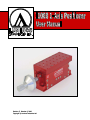
Revision 5, October 9, 2008
Copyright © Luminos Industries Ltd.
Table of Contents
Introduction to the I1000 Photonics Positioner .................................................................. 1
Feature Summary ............................................................................................................ 1
Getting Started .................................................................................................................... 1
Reading the Micrometers................................................................................................ 1
Connecting an Automated Positioner ............................................................................. 2
Actuator Control ............................................................................................................. 3
Mounting the Positioner.................................................................................................. 3
Mounting Devices and Accessories ................................................................................ 3
Accessories ..................................................................................................................... 3
I1000 Specifications............................................................................................................ 4
Stepper Motor Actuators..................................................................................................... 5
Actuators with Built-In Controller (A and B Type)........................................................ 5
Included Software ....................................................................................................... 5
Manual Control ........................................................................................................... 5
Actuators Without a Controller (AM and BM Type) ..................................................... 6
Actuator Specifications................................................................................................... 6
Available Options ............................................................................................................... 7
Dimensional Drawings........................................................................................................ 8
Unpacking and Transportation.......................................................................................... 10
Locking Strip Removal ................................................................................................. 10
Contact Us......................................................................................................................... 11
Mailing Address............................................................................................................ 11
Business Hours.............................................................................................................. 11
Phone Contacts.............................................................................................................. 11
Email Contacts .............................................................................................................. 11
Warranty ........................................................................................................................... 12
Table of Figures
Figure 1 - Connecting an Automated Positioner (A and B type actuators) ........................ 2
Figure 2 – I3000/I3005 3-Axis Positioner .......................................................................... 4
Figure 3 – Mini-din Actuator Connection .......................................................................... 6
Figure 2 – I3000/I3005 Positioner (manual) Dimensions - Front & End ........................... 8
Figure 5 – I3000/I3005 Positioner (manual) Dimensions - Top & Bottom........................ 8
Figure 4 – I3000/I3005 Positioner (stepper motor) Dimensions - Front ............................ 9
Figure 5 – I3000/I3005 Positioner (stepper motor) Dimensions - Top .............................. 9
Figure 8 – Unpacking........................................................................................................ 10
I1000 1-Axis Positioner User Manual
Introduction to the I1000 Photonics Positioner
Introduction to the I1000 Photonics Positioner
Able to handle loads of up to 1 kg, the I1000 single axis stage provides a stable platform
for many straight-forward positioning tasks. A large travel of 12.7 millimeters (1/2 inch),
makes the I1000 suitable where coarse alignment is required. The dual flexure design
ensures extremely linearity and eliminates the need to compensate the arcing motion
associated with single flexure designs. Furthermore, the flexure design is essentially
frictionless and does not exhibit any hysteresis or stiction of typical roller-bearing stages.
Internal damping makes the I1000 insensitive to vibration allowing it to be used on a
typical bench (without an optical table).
Feature Summary
•
•
•
•
•
•
•
•
•
•
All damped flexure
Manual or fully automated
Frictionless
Internal viscous damping
Insensitive to dust
Zero arc-error
Zero backlash
Resolution enhancing for highest resolution at lowest cost
10nm resolution when fitted with a differential micrometer
Stepper Motor Actuator delivering 0.1µm per micro step
With positioning this easy… the possibilities are endless.
Getting Started
Before unpacking the positioner, please read Unpacking and Transportation on page
10.
Reading the Micrometers
The following table gives the conversion necessary to interpret the numbers read from the
micrometer.
Axis
Z
Smallest Division (A)
0.001 inches
1 Rotation (B)
0.025 inches
Each line on the shaft of the micrometer corresponds to one rotation. The “smallest
division” refers to the divisions on the knob of the micrometer. Clockwise rotation of
each micrometer causes movement in a positive direction as shown in Figure 2 (pg. 4).
To calculate the position, count the number of divisions on the shaft between the current
position and zero. Multiply that number by the movement per rotation (B) given in the
table above. Then, count the number divisions on the knob from zero; multiply that
Luminos Industries Ltd.
1
I1000 1-Axis Positioner User Manual
Getting Started
number by the movement per smallest division (A in the table above). Add the two
products calculated to give the position. The formula is summarized as:
Position = (Shaft_Divisions x B) + (Knob_Divisions x A)
Note: If the coarse adjustment of the X or Y axis is moved, the position read from the
micrometer of that axis will not be the same physical position as before moving the
coarse adjustment.
Connecting an Automated Positioner
Figure 1 - Connecting an Automated Positioner (A and B type actuators)
To connect your positioner, use the following steps:
1. Connect the 9-pin adapter with the matching white connector to white connector
on the bottom actuator closest to the manual knob. On any positioner with more
than one axis, this will be the only white connector available on the bottom
actuator. (Do not disconnect actuators that are already connected).
2. Connect the other end of the adapter (a female DB9 9 pin connector) to the 9-pin
serial extension cable.
3. The end of the cable is a standard 9-pin female serial connection and should
connect to one of the serial ports on the back of the computer (or to a Serial-USB
adapter to utilize a USB port instead).
2
Luminos Industries Ltd.
I1000 1-Axis Positioner User Manual
Getting Started
4. Connect the 12-16V DC (minimum 800mA) power adapter to the bottom
actuator. The rest of the actuators are power through the daisy chain.
5. Plug the power adapter into a standard receptacle.
6. Install the software driver using the CD provided. Help for using the driver is
included as part of the installation.
Actuator Control
The documentation for actuator control is included in the accompanying compact disc (if
applicable). This format allows easy access from within most software development
environments.
Mounting the Positioner
The I1000 mounts using ¼-20 screws on 1 inch and 4 inch centers (see Figure 5 –
I3000/I3005 Positioner (manual) Dimensions - Top & Bottom, pg 8)
Mounting Devices and Accessories
The device mounting plate (shown in Figure 2, pg. 4) is where devices and accessories
are mounted. For dimensions, see Figure 5 on page 8.
Accessories
There are many accessories available including a contact sensing system for sensing very
small forces in the Z (focal) direction. Contact us if there is an accessory you require.
Luminos Industries Ltd.
3
I1000 1-Axis Positioner User Manual
I1000 Specifications
Device
Mounting
Plate
Y
Z
X
X Coarse
Adjustment
Y Coarse
Adjustment
Figure 2 – I3000/I3005 3-Axis Positioner
I1000 Specifications
Travel
Axis
Actuator1
Coarse
Total
Z – focus
12.7mm (0.5")
N/A
12.7mm (0.500")
Setability2 (Micrometer)
Axis
Resolution
Movement /Division
Z
0.25 micron (10µ-inch)
0.001"
Resolution (Stepper Motor – A Type)
Axis
Resolution
Total Steps
Z
100nm (4µ-inch)
128 000
Stage Configuration & Arc Error Motion
Axis
Flexure Type
Arc Error
Z
Dual
None - True Linear Motion
Along Axis
Stiffness
Comments
Z
130 kN/m
measured at the rotation center
Y
95 kN/m
measured at the rotation center
X
40 kN/m
measured at the rotation center
Linear Stiffness
4
Luminos Industries Ltd.
I1000 1-Axis Positioner User Manual
Stepper Motor Actuators
Torsional Stiffness
About Axis
Stiffness
Comments
Z – roll
75Nm/rad
measured at the rotation center
Y – yaw
100Nm/rad
measured at the rotation center
X – pitch
130Nm/rad
measured at the rotation center
Maximum Load
Static Load
Transient Load
Comments
10 lbs (4.5kg)
stage must be protected from shock
loading during transport and usage
2.2 lbs (1kg)
Physical Properties
Characteristic
Specifications
Comments
Construction
Aluminum
6061 & 7075 - T6 anodized
Weight
1.0kg
Approximate
Body Dimensions
4.50” x 1.75" x 3.80"
LxWxH excluding micrometers
Mounting Height
3.94"
Base to top of mounting plate
Mounting Configuration - Imperial
0.26" dia. holes
1.00" x 4.00"3 centers
Mounting Configuration - Metric
6.6mm dia. holes
25mm x 100mm centers
1/2"
Above top of mounting plate
1"
Out from end of mounting plate
Concurrent Rotation Center
1
'Actuator' refers to a micrometer or stepper motor.
2
Operator dependent
3
Compatible with 1.00" grid optical tables, units mount on 2" intervals with 0.25" allowance for routing of
cables etc.
Stepper Motor Actuators
Actuators with Built-In Controller (A and B Type)
The A and B type actuators do not require an external stepper motor driver - these slim
actuators actually contain an onboard RS-232 controller which interfaces directly with
any standard PC serial port (or USB port with a low cost adapter). Each Positioner is
shipped with a 15 Volt, 1 Amp DC Voltage adapter, a 4-pin Molex to 9-pin serial
adapter, and a 2m 9-pin extension.
Included Software
An included ActiveX/COM™ software component makes it easy to get up and running
quickly in any windows based development environment (including Visual Basic,
Labview, and C++, or any of the .NET languages).
Manual Control
A convenient knob at the end of the unit permits manual control. During a manual move
the actuator constantly updates the connected computer with its position. If accidental
movement is a concern, the manual control can be enabled and disabled via computer
control.
Luminos Industries Ltd.
5
I1000 1-Axis Positioner User Manual
Stepper Motor Actuators
Actuators Without a Controller (AM and BM Type)
The AM and BM type actuators are equivalent to the A and B type actuators without
controllers. They are provided with direct connections to the two phases of the bipolar
stepper motor (4 wires) and a Hall Effect limit sensor (3 wires) through a male 8-pin
mini-din connector.
This option allows those with an existing system for driving stepper motors to avoid
changing over to RS-232 based control. However, for new applications, this option is not
recommended due to the high cost of separate controllers.
6
7
3
8
4
1
Pin
1
2
3
4
5
6
7
8
5
2
Function
Motor Phase A1
Motor Phase A2
Motor Phase B1
Not Connected
Motor Phase B2
Home Sensor +5V
Home Sensor Signal
Home Sensor GND
Figure 3 – Mini-din Actuator Connection
Actuator Specifications
Description
Actuator Type
A
AM
Yes
No
Motor Type
Built-in Controller
B
BM
Bipolar Stepper
Steps Per Revolution
Yes
No
48
Motion Per Step
6.35 µm
Power Per Phase
12.7 µm
1.7W
Resistance Per Phase
84 ohms
14.7 ohms
Current per Phase
140 mA
340 mA
Inductance per Phase
55 mH
8.5 mH
Accuracy
< 12 µm
< 16 µm
Backlash
< 4 µm
< 8 µm
< 0.4 µm
< 0.8 µm
Repeatability
Power Supply
12V-16V DC unregulated 2.1mm center positive
plug (A and B type only)
Current Draw
Idle: 100 mA Moving: 320 mA
Table 1 - Actuator Specifications
6
Luminos Industries Ltd.
I1000 1-Axis Positioner User Manual
Available Options
Available Options
Z Actuator
Manual Imperial Micrometer (default)
A micrometer where the smallest division is 0.001 inches
(0.025” per revolution)
Differential Micrometer (Imperial)
A double threaded micrometer for increased resolution where the smallest
division is 0.00002 inches.
Stepper, Fine Travel, 0.1µm microstep, RS-232 Onboard Controller
Stepper, Long Life, 0.2µm microstep, RS-232 Onboard Controller
Stepper, Fine Travel, 6.4µm fullstep, Direct Mini-DIN 8
Stepper, Long Life, 12.8µm fullstep, Direct Mini-DIN 8
Mounting Axis
Horizontal (default)
The positioner is balanced in the horizontal and upright position.
Vertical
The positioner is balanced with the micrometers pointing up. This
configuration requires more preload on the z-axis.
Luminos Industries Ltd.
7
I1000 1-Axis Positioner User Manual
Dimensional Drawings
Dimensional Drawings
Figure 4 – I3000/I3005 Positioner (manual) Dimensions - Front & End
Figure 5 – I3000/I3005 Positioner (manual) Dimensions - Top & Bottom
8
Luminos Industries Ltd.
I1000 1-Axis Positioner User Manual
Dimensional Drawings
Figure 6 – I3000/I3005 Positioner (stepper motor) Dimensions - Front
Figure 7 – I3000/I3005 Positioner (stepper motor) Dimensions - Top
Luminos Industries Ltd.
9
I1000 1-Axis Positioner User Manual
Unpacking and Transportation
Unpacking and Transportation
Do not discard packaging! The warranty is void if a Positioner is not shipped in the
original packaging.
Locking Strip Removal
To prevent damage to the Z axis linkage during transportation a plastic locking strip is
inserted between the upper and lower part of the unit (see Figure 8, below). To remove
the locking strip, apply hand force to the upper portion of the unit (Z axis direction),
remove locking strip and carefully allow the unit to return to its pre-loaded position. This
procedure is applicable to all positioner types.
Figure 8 – Unpacking
10
Luminos Industries Ltd.
I1000 1-Axis Positioner User Manual
Contact Us
Contact Us
Thank you for purchasing a Luminos product. We want to ensure your experience is a
positive one. If you have any questions, concerns, or comments do not hesitate to contact
us.
Mailing Address
Luminos Industries Ltd.
8-58 Antares Drive
Ottawa, Ontario
K2E 7W6 - Canada
Business Hours
Monday to Friday: 8:00am-4:30pm EST
Phone Contacts
Telephone: 1 (613) 225-7661
Fax: 1 (613) 225-3391
Email Contacts
Sales: [email protected]
General Inquiry: [email protected]
Support: [email protected]
Luminos Industries Ltd.
11
I1000 1-Axis Positioner User Manual
Warranty
Warranty
All items manufactured by Luminos Industries Ltd. are warranted to meet Luminos
Industries' published specifications and to be free of defects in materials and
workmanship as defined in the specifications for 90 days after delivery. Luminos
Industries Ltd. will, at its own option, repair or replace without charge any listed item
discovered to be defective.
Luminos Industries Ltd. will not be held liable for any loss whatsoever beyond the
purchase price paid by the buyer for the goods to which claim is made. Luminos
Industries does not give implied warranties of merchantability, fitness for a particular
purpose, or of any other nature in connection with the sale of any Luminos Industries Ltd.
products.
Products not returned in original packaging will void this warranty.
This warranty does not extend to cover damage resulting from alteration, misuse,
negligence, abuse, normal wear and tear, or accident.
12
Luminos Industries Ltd.
58 Antares Drive
Ottawa, Ontario
Canada
K2E 7W6
613 225 7661 – tel
613 225 3391 – fax
www.luminosindustries.com
[email protected]