1
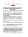
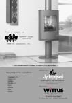
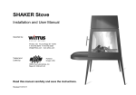
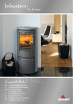
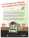
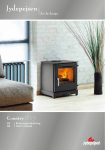
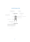
Report # 301-S-02c-4 UL 1482(2010) and S627-00(2000) - Read this manual carefully and save these instructions Installation and user manual Trendline 1+2+3 Troja 1+2+3 Softline Fineline 1+2 Zeus Athene Hera Avanti Cubic 109-166-215 Cubic Corner Cubic Wall Cubic W200 Cosmo Models Manufactured by: Ahornsvinget 3-7 DK-7500 Holstebro T.+45 96101200 F.+45 97425216 www.jydepejsen.com Imported by: PO Box 120 Pound Ridge NY 10576 T.914-764-5679 F.914-764-0465 www.wittus.com Version – 7/12 Contents 1. 2. 3. 4. 5. 6. 7. 8. 9. 10. 11. 12. 13. 14. 15. Description Wood-burning stoves from Jydepejsen A/S Before installing your stove Chimney Chimney connector Heat generation and distribution Sensible wood burning Technical information on wood burning Air supply and combustion Preparation for the first fire Lighting the stove Refueling Troubleshooting Maintenance of the stove Warranty Spare parts list Page 2 3 7 7 10 11 11 13 15 15 15 16 17 21 21 1 1. Wood-burning stoves from Jydepejsen A/S A wood burning stove from Jydepejsen A/S is a quality Danish product. Our stoves have been providing a cheerful, cozy atmosphere and excellent savings on heating in many homes since the company was founded in 1979. We continue to produce stoves that are among the best on the market. The key factors are simple operation, optimum combustion, timeless design and environmental awareness. From the start we created innovations that have since become the norm for quality European stoves. In many respects these pioneering ideas have helped Denmark maintain its position as Europe's leading producer of wood burning steel stoves. In the production, research & development we work purposefully towards reducing environmental impact. It is also important to us that our stoves achieve environmentally friendly combustion, which is ensured by Jydepejsen's long-standing design principles. All the products in this manual have been rated to 81% efficiency. To realize our mission of environment friendly combustion, it is your responsibility as a consumer to use the correct fuel and operate your stove according to the instructions. The aim of this manual is to guide and instruct stove owners in proper burning, and to minimize the risk of incorrect operation of the stove. Failure to follow instructions may result in property damage, bodily injury, or even death. It is therefore very important to read this manual carefully, and save the instructions. Correct operation is also vital with regard to our applicable warranty terms. Consult your local Building Inspector or Fire Marshall before installation to determine the need to obtain a permit. Also inquire about restrictions and installation inspection requirements in your area. For more information on wood burning visit the website http://woodheat.org/. We suggest that our wood burning heart products be installed and serviced by professionals who are certified in the U.S. by the National Fireplace Institute (NFI) or certified in Canada by the Wood Energy Technical Training (WETT). Take particular note of this symbol: This indicates special attention. Kind regards All at Jydepejsen A/S 2 2. Before installing your stove Jydepejsen stoves Cosmo, Cubic, Trend-linel+2+3, Troja 1+2+3, Soft-line, Fine-line, Zeus, Athene, Hera and Avanti are tested by OMNI-Test Laboratories, Inc. of Oregon and are listed to UL 1482-2010 and ULC S627-2000. They are also EPA certified and meet the more stringent WA State Environmental standards. If the stove is not installed properly, a home fire may result. To reduce the risk of fire, follow the installation instructions. Contact local building or fire officials about restrictions and installation inspection requirements in your area. It is recommended to install a smoke detector in the room or nearby room where the stove is being installed as a precautionary measure. DO NOT INSTALL IN A MOBILE HOME. Floor plate/floor protection A floor plate of non-combustible material (tempered glass floor plates are acceptable) must cover under the stove and extend 16" (41 cm) (18" (45 cm) in Canada) in front of the stove door, 8" (20 cm) beyond the sides of the fuel-loading door, and under the pipe and 2" (5 cm) beyond each side for back venting. In Canada, the 8" (20 cm) floor protection is required beyond the sides of the stove and in the back of the stove (0" in the back for the US). If the material has an R (Thermal resistance) rating use the designated thickness and no conversion is needed. R values can be added for multi-layered materials. If the material has a K (Thermal conductivity) rating convert this to an R rating using the formula R=1/kxt (t=thickness in inches). If the material has a C (Thermal conductance) rating convert this to an R rating using the formula R=1/C. Floor/ foundation wall The stove must be installed/hanged on a non-combustible foundation/at a non-combustible wall - i.e. where a tile or brick floor is non-existing, the stove must meet the demands for the distance to combustible material under/above/beside the stove, according to applicable legislative requirements. Consult you dealer before installing the stove. Wall and corner models If you have a Cubic Wall/Cubic Corner/Cubic W200 the stove must be installed with the enclosed furnishings and should meet the NFPA211 guidelines. The installation must not weaken the chimney construction. The anchoring must be done in consultation with your dealer/chimney sweep. Cubic 166/215 The tall models may reach the ceiling (or less than the 18" clearance). If the unit does not meet the proper clearance to the ceiling, the chimney pipe must be used to connect to the fire box. 3 MINIMUM CLEARANCES TO COMBUSTIBLES Description Trendline 1-2-3/ Troja 1-2-3/ Softline/ Cosmo Zeus/ Athene/ Hera/ Avanti/ Fineline 1-2 Cubic 109/166/215/Wall/W200/Corner A. DISTANCE TO SIDE WALL B. DISTANCE TO BACK WALL C. CORNER DISTANCE TO SIDE WALLS US/CANADA US/CANADA US/CANADA 18" (46 cm) 10" (25 cm) 7" (18 cm) D. CONNECTOR PIPE TO SIDE WALL E. CONNECTOR PIPE TO BACK WALL US/CANADA US/CANADA 26" (65 cm) 16" (41 cm) F. CORNER PIPE TO SIDE WALLS US/CANADA 16" (41 cm) G. DISTANCE TO FURNITURE H. FRONT FLOOR PROTECTION J. DISTANCE TO WALL (TURNABLE) US/CANADA 36" (92 cm US 16" (41 cm) CANADA 18" (46 cm) US 8" (20 cm) beyond the sides of the fuel loading door CANADA 8" (20 cm) beyond the sides of the stove US/CANADA 40" (100 cm) K. CONNECTOR PIPE TO WALL (TURNABLE) CEILING TO TOP OF STOVE US/CANADA US/CANADA 48" (120 cm) 36" (92 cm) US/CANADA 18" (46 cm) I. SIDE FLOOR PROTECTION CEILING TO CONNECTOR PIPE Note: A heat shield or protective wall may be used to reduce clearances if approved by the regulatory authority. Clearances to noncombustible materials are 2" (5cm), but note that "noncombustible" must be solid cement or cement block (not brick or tile over combustible material). 4 DIAGRAMS FOR CUBIC SERIES CUBIC 109/166/215 CUBIC WALL CUBIC CORNER r L L CUBIC WALL CUBIC CORNER A I H G 5 Installation of Trendline 2 without the turntable feature If the Trendline 2 stove is to be used without the turntable feature (screws still attached), please follow the standard installation procedures (page 5) under Wall View and Corner View for the correct clearances. Installation of Trendline 2 with the turntable If the Trendline 2 is being used with the turntable feature, first remove the locking screws located under the stove's firebox (as shown below). This allows the stove to turn freely within its 90° range. Position and center the stove properly as described: Turn the stove to the left most position. Measure and insure that all the standard required clearances are met in that position. Turn the stove to the right most position. Measure and insure that all the standard required clearances are met in that position as well. Make adjustments until all the clearances are met in both positions. These include stove, pipe, and floor plate clearances. If placed in the center of a room (with a 360° turn range), remember that all clearances to combustible materials must be 36" for the Trendline 2. IMPORTANT - Failure to follow these instructions may result in property damage, bodily injury, or even death. You must follow the specific clearances for the turn-table feature in order not to void the warranty and liability coverage. 6 3. Chimney The Jydepejsen stoves must be installed using a Class A UL 103 HT approved factory-built chimney system or a code-approved masonry chimney with a flue liner. In Canada, the installation must conform to NFPA 211 or CAN/CSA-B365, Installation Code for Solid-FuelBurning Appliances and Equipment guidelines and methods. The chimney must extend through the roof at least 3' (1 m), and 2' (6 m) above any structure within 10' (3 m). The condition of the chimney and height is very important. We suggest a total minimum height of 10' (3 m). Both the chimney and the required chimney connector must be in good condition and kept clean. Note! Mount the special collar using the included hardware. When installing the first piece of pipe (at the stove), place the pipe over the collar (except on the Trendline 2 where the crimped end goes inside the collar!), which is designed so any moisture or creosote will drip back into the stove and burn away. If using a crimped pipe, trim or cut that section off at the bottom and place it over the collar. Install the remaining stovepipe segments with the crimped end down whenever possible. The hole in the casting is designed for any moisture to drip back into the stove. Required Installation Components A. Chimney cap B. Insulated chimney C. Storm collar D. Roof flashing E. Ceiling support box or joist shield / firestop spacer F. Chimney connector pipe 4. Chimney connector Aluminum and galvanized steel pipe is not acceptable for use with our woodstove. These materials cannot withstand the extreme temperatures of a wood fire and can give off toxic fumes when heated. Do not use the connector pipe as a chimney. Each chimney connector or chimney connector section must be installed to the stove flue collar and to each other with the male (crimped) end toward the stove. Chimney Connector 7 This prevents any amount of condensed or liquid creosote from running down the outside of the pipe or the stove top. All joints, including the flue collar connection must be secured with three sheet metal screws to ensure that the sections do not separate. For the best performance the chimney connector should be as short and direct as possible, with no more than two 90° elbows. The maximum horizontal run is 36" and a recommended total length of chimney connector should not exceed 10 feet. Always slope horizontal runs upward 1/4" per foot toward the chimney. Note the chimney connector pipe should not pass through an attic or roof space, closet or similar concealed space, or a floor or ceiling. DO NOT CONNECT TO OR USE IN CONJUCTION WITH ANY AIR DISTRIBUTION DUCTWORK (unless specifically approved for such installations). DO NOT CONNECT WITH ANY SYSTEM SERVING ANOTHER APPLIANCE. For venting vertically into a Class A chimney, single wall pipe (at least 24 gauge) may be used in the room where the stove is installed. Refer to the manufacturer's instructions for the connection to the listed chimney. The chimney/chimney connector must not be smaller than 6" (15 cm) in diameter. For venting directly into a masonry chimney or through a thimble, the top of the single wall pipe must be at least 18" (46 cm) below a combustible ceiling and conform to NFPA 211 or CAN/CSA-B365, Installation Code for Solid-FuelBurning Appliances and Equipment guidelines and methods. See diagram below. Fresh air Modern, well-insulated buildings should have fresh-air vents to admit fresh air from outside. Modern buildings are now so well insulated that the volume of air indoors can be low. A regular supply of air to the building from outside prevents negative pressure indoors. Connector Pipe 18”(46cm) below ceiling Chimney Flue Masonry Min. 2”(5cm) Insulated Chimney Min. 2”(5cm) For rear venting or other not listed configurations, consult the local building codes and follow the NFPA 211 or CAN/CSA-B365, Installation Code for Solid-Fuel-Burning Appliances and Equipment guidelines. If the chimney connector is fitted with a baffle, it must be manually operated, visibly placed for ease of use, and must not close completely. Consult your chimney expert if you have any questions. Make sure that there is easy access to the chimney cleanout door. Read the instructions on page 7 carefully before connecting: "Chimney Connector Systems and Clearances from Combustible Walls for Residential Heating Appliances". 8 Chimney Connector Systems and Clearances from Combustible Walls for Residential Heating Appliances A. Minimum 3.5 in (90 mm) thick brick masonry all framed into combustible wall with a minimum of 12-in (305 mm) brick separation from clay liner to combustibles. The fireclay liner (ASTM 315, Standard Specification for Clay Fire Linings, or equivalent) minimum 5/8 in (16 mm) wall thickness, shall run from outer surface of brick wall to, but not beyond, the inner surface of chimney flue liner and shall be firmly cemented in place. B. Solid-insulated, listed factory-built chimney length of the same inside diameter as the chimney connector and having 1 in (25.4 mm) or more of insulation with a minimum 9 in (229 mm) air space between the outer wall of the chimney length and combustibles. The inner end of the chimney length shall be flush with the inside of the masonry chimney flue and shall be sealed to the flue and to the brick masonry penetration with non-water-soluble refractory cement. Supports shall be securely fastened to wall surfaces on all sides. Fasteners between supports and the chimney length shall not penetrate the chimney liner. C. Sheet steel chimney connector, minimum 24 gauge (.024 in./.61 mm) in thickness, with a ventilated thimble, minimum 24 gauge (.024 in/.61 mm) in thickness, having two 1 in (25.4 mm) air channels, separated from combustibles by a minimum of 6 in (152 mm) of glass fiber insulation. Opening shall be covered, and thimble supported with a sheet steel support, minimum 24 gauge (.024 in/.61 mm) in thickness. Supports shall be securely fastened to wall surfaces on all sides and shall be sized to fit and hold chimney section. Fasteners used to secure chimney section shall not penetrate chimney flue liner. D. Solid insulated, listed factory-built chimney length with an inside diameter 2 in (51 mm) larger than the chimney connector and having 1 in (25.4 mm) or more of insulation, serving as a pass-through for a single wall sheet steel chimney connector of minimum 24 gauge (.024 in/.61 mm) thickness, with a minimum 2 in (51 mm) air space between the outer wall of chimney section and combustibles. Minimum length of chimney section shall be 12 in (305 mm) chimney section spaced 1 in (25.4 mm) away from connector using sheet steel support plates on both ends of chimney section. Opening shall be covered, and chimney section supported on both sides with sheet steel supports securely fastened to wall surfaces of minimum 24 gauge (.024 in/.61 mm) thickness. Fasteners used to secure chimney section shall not penetrate chimney flue liner. 9 Before installation, it is also important to check that the Vermiculite panels are correctly fitted in the combustion chamber. The wood holder in the combustion chamber is not to be removed. On some baffle plates you will find a metal band. This band is mounted for transport protection only, and should be removed. 5. Heat generation and distribution All Jydepejsen wood-burning stoves are two stoves in one. Inside is the actual stove, produced from strong steel plates, and on the outside a covering of steel, ceramic tiles or soapstone. There are two major types of heat: radiant heat and convection heat. In the airspace between the actual stove and the covering, convection heat is generated. The air is drawn in at the bottom of the firebox. The heated air then flows upwards and begins to circulate throughout the room, subsequently dispersing into the neighboring rooms, providing perfect heat distribution. So the question of where to position your stove is an important one. The ideal location is fairly central, in the room where you require most heat. Unlike radiant heat, which is highly concentrated around the stove, convection heat flows upwards and spreads to neighboring rooms. It is very important to ensure that your chimney has a good draft. Your dealer or your chimney sweep will be able to guide and advise on your chimney conditions. Ensure that there is sufficient combustion air in the room in which the stove is installed, which can be sourced from another room or from an outside air supply. Rooms with negative pressure (e.g. use of exhaust fan) or newer air-tight buildings are particularly suited for air supply from outside. An outdoor air supply is available as an option, and should be installed by a qualified person. Follow the operating instructions and use seasoned wood, which burns easier and cleaner in the combustion chamber, until a proper draft is obtained. For further information on using wood and lighting and managing the fire, please refer to sections 5 - 10. Please note that the stove paint will harden during the first few initial fires. This means that the stove will generate smoke and an odor of paint, which will dissipate after about 1 hour's operation. It is a good idea to ensure effective ventilation during this phase. Also, avoid touching the stove during the curing process. The stove will expand and contract during the lighting and cooling phase, possibly resulting in creaking noises. This phenomenon is completely normal for steel stoves. 10 6. Sensible wood burning When dry wood is burned in a wood-burning stove the following process occurs (over a period of approx. 1 hour): After lighting the log starts to dry and heats up. After drying the temperature of the wood rises to approx. 300 - 400° F (150 - 200°C) and is converted into volatile gases and charcoal. As the wood is gasified a certain portion of the gases produced burn and are converted into carbon dioxide and water. During this phase the temperature rises to around 1100 1500° F (600 - 800° C) and a plentiful supply of air is required. If the air supply is accidentally reduced, the flames will be smothered, but this will not stop the conversion of the wood into gas. The unburned gas will then flow out into the chimney, causing a nuisance outdoors and build up of creosote. Next the charcoal will burn, which requires very little air supply. Finally, new wood must be laid on the glowing charcoal cinders. Warning - It is extremely important to ensure that you do not overheat your stove, as this can cause irreparable damage. This kind of damage is not covered by the warranty. Extremely high combustion temperatures can occur when using inappropriate fuel, such as kiln-dried wood, coal, pressure-treated wood, scrap wood. DO NOT USE CHEMICALS OR FLUIDS TO START THE FIRE. DO NOT BURN GARBAGE OR FLAMMABLE FLUIDS SUCH AS GASOLINE, NAPHTHA, OR ENGINE OIL. NEVER USE GASOLINE-TYPE LANTERN FUEL, KEROSENE, CHARCOAL, LIGHTER FLUID, OR SIMILAR LIQUIDS TO START OR `FRESHEN UP' A FIRE. KEEP ALL SUCH LIQUIDS WELL AWAY FROM THE HEATER WHILE IT IS IN USE. HOT WHILE IN OPERATION. KEEP CHILDREN, CLOTHING AND FURNITURE AWAY. CONTACT MAY CAUSE SKIN BURNS. DO NOT STORE SOLID FUEL WITHIN SPACE HEATER INSTALLATION CLEARANCES OR WITHIN THE SPACE REQUIRED FOR CHARGING AND ASH REMOVAL. WARNING - Do not use substitute materials for glass replacement. Incorrect wood burning Too much air supplied to the combustion process causes an uncontrollable fire that will heat the entire stove very rapidly to an extremely high temperature. This can happen if you fire with conditions that produce an extra-strong draft in the chimney. Never fill the stove completely with wood. It is better to heat a stove up slowly. This will prevent cracked tiles/soapstone, damage to welds and annealing of the iron. Overfilling the firebox also substantially reduces the useful life of the vermiculite panels, as cracks are more easily caused. The log size should be about 2" (5 cm) less than the width of the firebox. Start slowly with a "normal" fire from the bottom, and slowly build it up to a maximum of three logs. 7. Technical information on wood burning 1 kilo of dry wood is made up of 20% water, with the remaining 80% divided into 60% gas and 20% charcoal. The 60% gas only contains around half the energy content of the wood, while the 20% charcoal contains the other half. To achieve optimum combustion, the temperature must reach 1100 - 1500° F (600 - 800° C). Reload with a few pieces of wood at a time. If too much wood is placed on a layer of embers, the air supplied will not be sufficient to attain the required temperature, and the gases will disappear out through the chimney unburned. It is vital to supply air to the fire immediately after adding fuel, so there are flames in the firebox, and the gases burn. (Refer to the Refueling section 9 for further guidance). 11 Remember that three logs will burn just as quickly as one The quantity of firewood determines the heat emission - the more heat you require, the more wood you should add at each refueling. Types of fuel and heating values All the stoves are constructed and approved for burning wood. Combustion involves conversion of the fuel from solid form into gases, water vapor and charcoal. The heating value is an expression of the content of combustible ga ses - stated in kcal/kg. All wood has roughly the same heating value per kilogram. The lighter the wood, the more that must be used to achieve the same heating value as with a heavier species of wood. Type of wood Beech and oak Ash Maple Birch Mountain pine Fir Poplar Dry wood - Lbs./ft3 (Kg/m3) 36.2 (580) 35.6 (570) 33.7 (540) 31.8 (510) 30.0 (480) 24.3 (390) 23.7 (380) Compare to beech 100% 98% 93% 88% 83% 67% 65% As mentioned, air-dried wood contains around 20% water, corresponding to a heating value of approx. 4 kWh/kg equivalent to approx. 3440 kcal/kg (1 kW = 860 kcal.) WARNING! NEVER burn impregnated wood, painted wood, laminated plastic, plywood, chipboard, refuse, milk cartons, printed matter, charcoal, or similar. Use of such materials will invalidate your warranty, as this may emit toxic, corrosive and hazardous fumes when burned. They may also cause a buildup of the toxic gas dioxin or carbon monoxide, which is damaging to the stove and the environment and may cause bodily harm or death. Fuel Recently-felled wood contains 60-70% water and must therefore be seasoned before it can be used in a wood-burning stove. It must be cut, split, and air dried, and must contain no more than approx. 25% water before use. This equates to the wood being left in the open for approx. 1 year - covered only to protect against rain. It is very important to always use pure, dry wood. Damp wood requires a lot of air for combustion, as extra energy in the form of heat is needed to dry it out. Heat emission is therefore minimal. Creosote - Formation and Need for Removal When wood is burned slowly, it produces tar and other organic vapors, which combine with expelled moisture to form creosote. The creosote vapors condense in the relatively cool chimney flue of a slow-burning fire. As a result, creosote residue accumulates on the flue lining. When ignited, this creosote makes an extremely hot fire. The chimney and chimney connector should be inspected at least once every two months during the heating season to determine if a creosote buildup has occurred. If creosote has accumulated, it should be removed to reduce the risk of a chimney fire. If a significant layer of creosote has accumulated (3 mm or more), it should be removed to reduce the risk of a chimney fire. In case of chimney fire shut down all air regulations. 12 8. Air supply and combustion Preheated air The stove utilizes a combustion technology involving preheated air. The air supply for the combustion process comes from an air inlet and is then conducted through ducts in the stove that become warm when the stove is in use. The advantage of this technology is that the air is already warm when it enters the firebox, so a high combustion temperature can be attained very rapidly. Startup and primary air supply Most of the stoves are designed with both a startup and primary air vent. The startup air vent supplies a very direct volume of air, which only serves a purpose in the lighting phase. The startup air supply should therefore only be used when lighting the stove. The primary air vent, however, is used for air control once the stove is lit. Startup air is defined as combustion air for burning the "mass of wood" and stimulates production of volatile gases. Primary air is used to burn off the gases at high temperatures (above 1,000° Fahrenheit (540° C)) and to keep the glass free of soot. For wood to burn correctly, the right amount of air has to be supplied at the right time and place. In the Jydepejsen DuplicAir system, the startup and primary air are combined into one air supply system. Air circulation when stoking Startup air 13 There are two other non-adjustable air systems on the stove; secondary air and direct air. Secondary air: To ensure a better combustion of gasses, the stove is constructed with secondary air holes in the baffle plates. Preheated air is supplied through these holes, which ensures burning of the last amount of gases before they slip out through the chimney, even if the primary air has been shut down. Secondary air flow Direct air: Direct air contributes to a cleaner and more efficient combustion at lower temperatures. Preheated air is supplied directly into the fire and makes sure that the bed of embers do not die out. Direct air flow 14 9. Preparation for the first fire Once your stove is installed and all instructions have been read, the first fire can be started. However, please take careful note of the following: The baking liner should be removed before the initial lighting. A sudden temperature change could cause it to crack. Tiles and soapstone are not covered by the warranty, so ensure that they are at least at room temperature before lighting up the stove. The baffle plate and vermiculite panels may crack under hard impact. These are not covered by the warranty, so avoid tossing the wood in the firebox. Avoid touching the stove during initial fires, as the paint is hardening at this stage. Otherwise this may cause scratches in the paint. It is a good idea to ensure effective ventilation during the first firing, as the stove will generate smoke and an odor of paint. The smoke and paint odor will dissipate after about 1 hour's operation and is not hazardous to health. Do not use grate or elevate Fire — build wood fire directly on hearth. 10. Lighting the stove 1. Turn the air wheel to the maximum (startup air) 2. Add crumbled paper / firelighters and kindling wood to the bottom of the fire box (combustion chamber). 3. The kindling (about 3 lbs or 1.5 kg) is to be built up crosswise. 4. Light the fire. 5. The door should be ajar for a couple of minutes during the lighting phase. 6. The air wheel must be adjusted down after approx. 10 minutes (primary air); how much depends on the chimney draft - however, the air supply must be diminished to the point where you obtain steady and calm flames. Caution: Do not build the fire to close to the glass because damage to the door can occur. Once there is a good bed of embers in the stove, you can add wood. It is important not to open the door while there are flames in the stove, as this may cause smoke to flow out into the room. Add wood on the basis of your heating requirements. However, never add more than 4.4 lbs or 2 kg of wood every 1.5 - 2 hours. Keep the doors closed during normal operation. Please remember that the exterior surfaces especially the top and front of the stove in particular will become very hot during burning. Do not operate the stove if the glass is broken. 11. Refueling 1. Turn the air wheel to the maximum. 2. To minimize the back draft, the door should be ajar for about one minute before you open it completely. 3. Open the door slowly. 4. Add 2 - 3 pieces of firewood to the combustion chamber. 5. Close the door. 6. Turn down the air supply when the fire has caught the wood, to obtain steady and calm flames. 15 12. Troubleshooting Combustion problems can arise if the combustion conditions are not optimal. This can be corrected by following the advice given below. Problem Explanation •flue vent is closed. The The access hatch In the chimney Is defective or missing The chimney Is blocked by a bird's nest or similar. The flue pipe is sooted up, or there is an accumulation of soot on top of the baffle plate. The chimney is too small. The baffle plate may be positioned incorrectly. Negative pressure in the house Remedy Insufficient draft ■ Open the flue vent. Contact your chimney sweep/stove dealer for further advice, or clean the flue pipe and firebox. Check the fitting of the baffle plate – see the operating instructions. In well-insulated buildings negative pres-awe can occur - increase the air supply to the room. The baffle plate may be positioned incorrectly. If using kiln-dried wood, this requires less air than normal wood. The air vent is constantly wide open. The sealing strips on the door are worn and pressed completely flat. The chimney is too large. Too much draft • • The glass pane is sooting up Clouded glass or with white film ■ The wood is too wet. The air vent is not sufficiently open. a Poor combustion (too low temperature in the stove). Incorrect combustion (burning waste wood, painted wood, impregnated wood, laminated plastic, ply wood or similar.) Smoke comes out • Into the room when the door is opened White smoke • Black or grayish black smoke Pressure compensation is occurring in the firebox. The chimney is not a suitable size for the firebox. • Check the fitting of the baffle plate see the operating instructions. Reduce the air supply. Check the sealing strips. If these are worn, replace them as described In the operating instructions. Contact your chimney sweep/stove dealer for further advice. Dry wood with a maximum of 20% moisture should be used. The air vent must be opened to supply more air for combustion. ■ Follow the instructions for correct burning as specified in this manual. Ensure that you use pure, dry wood in your stove. • Open the air vent wide for about 1 min. before opening the door - avoid opening the door rapidly. Check the height of the chimney. It may be too short for the minimum draught required from the chimney. The combustion temperature is ■ Increase the air supply. too low. Always ensure that you use pure, dry The wood is too damp and wood in your stove. contains water vapor. ■ Incomplete combustion. • Increase the air supply. Lighting and burning problems are usually due to wet wood or insufficient draft. 16 13. Maintenance of the stove Gaskets and vermiculite panels need to be replaced. How often depends on how much you use your stove. In some cases every year, others every second or third year. Generally, the gaskets need replacing when it is flattened, and the door no longer fits tightly against the front of the stove. A new set of gaskets with glue can be purchased from your local dealer. Vermiculite panels must be replaced when they are worn thin, or when possible cracks are so wide that you can actually see steel through them. If the panels are not replaced on such occasions, they lose their power of insulation and heat reflection. Movable and mechanical parts should be greased once a year with a heat-resisting lubricant (closing mechanisms, hinges etc). Door Inspect the seals on the door and ash pan front, and replace if they will not close tightly. If the glass pane is dirty, clean it gently with a warm wet cloth and a little mild detergent, dipped in ash. Check that the seam between glass panel and door is completely airtight. If necessary, tighten any screws holding the inner frame in place - but not too hard, as it could crack the glass. If the glass is still loose, replace the gasket. It is important to maintain all seals in good condition. WARNING: DO NOT CLEAN THE GLASS WHEN THE STOVE IS HOT. Disposal of ashes Ashes should be placed in a steel container with a tight fitting lid. The closed container of ashes should be placed on a noncombustible floor or on the ground, well away from all combustible materials, pending final disposal. If the ashes are disposed of by burial in soil or otherwise locally dispersed, they should be retained in the closed container until all cinders have thoroughly cooled. Other waste shall not be placed in the metal container. Vermiculite The heat-reflecting and insulating panels in the firebox of all wood-burning stoves from Jydepejsen are made of vermiculite. This material in its basic form consists of laminated minerals, and is supplied by an ISO 9001 certified company. Vermiculite poses no health hazards. It offers various benefits in terms of heat reflection, insulation and utilization, thereby helping to provide Jydepejsen stoves with an even higher combustion temperature, improved degassing of the wood and, consequently, greater efficiency in the stove. If the vermiculite panels are very worn (less than half thickness), new ones should be ordered. Contact your dealer, who will be happy to assist you. You can check page 17 to see how the panels are fitted in the stove. Cleaning guide The wood-burning stove (including the chimney and chimney connector) should be thoroughly checked and cleaned at least once during the course of the heating season. The flue gas outlet above the flue gas baffle and the stove connector should be inspected in particular. Check the stove only when it is cold. Before sweeping of your stove, the baffle plates should be removed. This will allow loose soot from the chimney to drop into the firebox. See page 19 - instructions on how to change the vermiculite panels. The air control should be closed to prevent soot and ash spilling into the room. After sweeping, clean any soot and ash from the vermiculite holders in the firebox. The baffle plates can then be put back in place. If creosote has accumulated, it should be removed to reduce the risk of a chimney fire. Do not use abrasive cleaners when you clean your stove at the in/outside. 17 Ash All wood-burning stoves from Jydepejsen have a large ashpan. Empty it before it fills completely, and do not allow the ash to collect in a cone under the shaker grate. Ash is an excellent insulator, and so the temperature of the grate can get very hot, and the grate could be damaged. External maintenance Maintenance of Jydepejsen wood-burning stoves is pretty much the same as for the rest of your furniture: use a cloth and mild soapy water without solvents. After cleaning, wipe the stove with a dry cloth. The stove can be carefully repainted, as necessary, using Senotherm 12-1644 aerosol paint in either black or grey, as appropriate for your particular stove. This paint can be purchased from your stove dealer. Ceramic tiles and soapstone The finished ceramic tile Dimensional accuracy and colorfastness are trade requirements and demonstrate the quality level of the tile manufacturer. With natural raw materials, variations and shading may occur or small fine glazing cracks and clouding may form. Modern technology ensures that such reactions in the surface structure do not affect the quality of the finished tile. These textures in the surface are therefore not flaws, but rather a mark of the craftsman’s individuality. If you discover any visible cracks in your ceramic tiles on unpacking, please contact your dealer immediately. Cleaning ceramic tiles Ceramic from Jydepejsen is simple to maintain. Wiping the tiles with a damp cloth is generally adequate. For more stubborn marks, use a little mild soapy water. Like other natural products, ceramic tiles cannot tolerate strong acids or leaching solutions. So, avoid strong detergents. With correct and careful maintenance your ceramic tiles will radiate heat and character for many years to come. Production of soapstone Manufacturing the large soapstone blocks is a very expensive process. The preparation involves rough and fine cutting, shaping and beveling, regular quality control, final inspection of each soapstone tile and selection of sets of soapstone tiles. Dimensional accuracy is required, but soapstone is a natural product, and shading will certainly occur. This is a mark of nature's own unique design. If you discover any visible cracks in your soapstone tiles on unpacking, please contact your dealer immediately. Cleaning soapstone Soapstone is very simple to clean. Wiping the soapstone with a damp well-squeezed cloth soaked in lukewarm water is generally sufficient. Avoid all types of detergent. Any minor scratches can be carefully removed using very fine sandpaper. Should any of your soapstone tiles need repairing, please contact your dealer. If soapstone is heated to more than 932° F (500° C), brownish blotches will appear on it. Should this occur, it is a question of the soapstone having been overheated, which is not covered by the warranty. With correct maintenance the soapstone cladding on your stove will retain its beautiful and individual character for many years to come. 18 Replacing door gaskets (except the Cubic series) 1. Remove the gasket from the inner frame and clean the band mark (it is not necessary to remove the door from the stove). 2. Add a band of heat-resistant glue on the band mark. 3. Push new gasket down into the mark. 4. Close the door and let the glue harden for about 24 hours, before you open the door again. If you do not let the glue harden sufficiently before you open the door, the gasket may fall out. Replacing the gasket at the glass (except the Cubic series) 1. 2. 3. 4. 5. 6. Lift the door from the hinges and place it on a flat base. Dismount bolts / screws from the inner frame. Dismount the bolt and the ratchet that hold the handle. Lift off the inner frame. Remove the old gasket from the glass. Add new gasket to the glass. Remounting of the glass takes place in the opposite order. Replacing door gaskets - Cubic series 1. Remove the gasket from the inner frame 2. Push new gasket down into the groove. Replacing the gasket at the glass - Cubic series 1. 2. 3. 4. 5. 6. Lift the door from the hinges and place it on a flat base. Dismount bolts and screws from the closing system. Dismount 2 screws at the bottom and 2 screws at the top. Lift off the inner frame. Remove the old gasket from the glass. Add new gasket to the glass. Remounting of the glass takes place in the opposite order. Change of the vermiculite panels 1. Lift up and turn the lower baffle plate a little, pull it down along the side panels and out through the door. 2. Remove the two side panels in the front. 3. Remove the two side panels in the back. 4. Now you can remove the upper baffle plate. 19 14. Warranty Brand-new wood-burning stoves from Jydepejsen A/S come with a 5-year warranty. The warranty covers defects in materials or workmanship. Use only authentic Jydepejsen stove spare parts, and use of any other parts would disqualify the warranty. Any claims during the warranty period should be directed to the dealer who sold the stove. All stoves from Jydepejsen come with their own individual serial number on the type plate on the back of the stove. Please quote stove model and serial number to your dealer in connection with service tasks. In the event of warranty repairs, a signed and dated invoice must also be produced, showing the dealer's name. The warranty does not cover dismantling, transport and reassembly of your stove. No compensation will be granted for: Damage during transport Damage to other articles resulting from use of the stove Damage arising from misuse, such as overheating — avoid this by reading the operating instructions carefully The directions in the operating instructions have not been followed Abuse of door glass WARNING do not strike or slam the door or the glass. Normal wear and tear parts such as vermiculite panels, baffle plates and gaskets are not covered by the warranty. Furthermore, glass, ceramic tiles and soapstone are not covered by the warranty. If any of the above mentioned need replacing, new parts can be ordered from your dealer. 15. Spare parts list Article No. 44101125-0 44101130-0 44101120-0 44101115-0 56100116 44101110-0 44101100-0 44101070-0 44101135-0 44001600 56100039 56700020 55015150 56100200 55000100 55104140 44300120 44300070 4490000-0 20 Article description Vermiculite side panel, right Vermiculite side panel, left Vermiculite side panel, left, beveled Vermiculite side panel, right, beveled Vermiculite front panel for Cubic series Vermiculite rear panel Vermiculite set Vermiculite baffle plate, upper Vermiculite baffle plate, lower Glass Glass for Cubic series Glass for Cosmo series Cast-iron bottom Cast-iron bottom for Cubic series Shaker grate Ash pan Gasket set with glue Gasket for Cubic series Direct air kit Dimensions H x B x D 400x336x4mm 469x458x4mm 489x340x4mm Thickness: 9 mm Thickness: 9 mm Capacity: 3.5 I Ø 9mm 20 x 7 mm Cubic series - assembly Cubic Wall : The stove must be prepared for either top or rear outlet. Standard construction is rear outlet. Fasten the furnishing on the wall. Place the stove on the lower hooks on the furnishing, tip up the stove and fasten it. Cubic Corner : The stove must be prepared for either top- or rear outlet. Standard construction is rear outlet. Fasten the furnishing on the wall. Place the stove on the lower hooks on the furnishing, tip up the stove and fasten it. 1 Back side of stove Back side of stove 21 Cubic W200 : The stove must be prepared for either top- or rear outlet. Standard construction is rear outlet. Fasten the furnishing on the wall. Place the stove on the lower hooks on the furnishing, tip up the stove and fasten it. Assemble the stove by pushing the steel cladding in and over the stove. Fasten the cladding to the wall by using 4 screws - screw holes are located in the fire box. Repeat the procedure for the bottom plate. Back side of stove Cubic 109: The stove is available with top- or rear outlet. Standard construction is top outlet. Adjusting is possible by using the 4 adjusting screws in the wood compartment. Cubic 166: The stove is available with top- or rear outlet. Standard construction is top outlet. Adjusting is possible by using the 4 adjusting screws in the wood compartment. Cubic 215: The stove is available with top- or rear outlet. Standard construction is top outlet. Adjusting is possible by using the 4 adjusting screws in the wood compartment. 22 Trendline soapstone - convection 23 Trend-line with full soapstone cladding Soapstone assembling 24 Softline with full soapstone or ceramic cladding Soapstone assembling 25 Softline with full soapstone or ceramic cladding Ceramic assembling 26 Manufactured by: xxxxxxxx Ahornsvinget 3-7 DK-7500 Holstebro T.++45 96101200 F.++45 97425216 www.jydepejsen.com Imported by: PO Box 120 Pound Ridge NY 10576 T. 914-764-5679 F. 914-764-0465 www.wittus.com