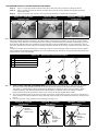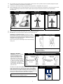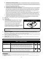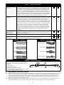
1
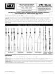
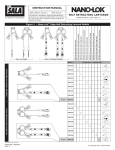
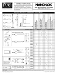
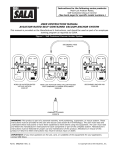
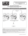
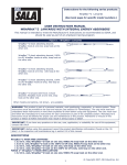
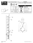
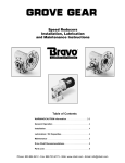
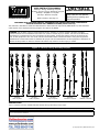
DBI-SALA
USER INSTRUCTION MANUAL
EZ Stop™ Energy Absorbing Lanyards
EZ Stop™ Force2™ Energy Absorbing Lanyards
EZ Stop™ WrapBax™2 Lanyards
EZ Stop™ Modular Lanyards
A
Capital
Safety
The
Ultimate
in Fall Company
Protection
Model numbers: See Page 13
Energy Absorbing LanyardS
Please read this User Manual
carefully before installing and
using this product.
Lanyards With Integral Energy Absorbers and Energy Absorber Components
Used in Personal Fall Arrest Systems (ANSI Z359.13)
his manual is intended to meet the Manufacturer’s Instructions as required by ANSI Z359.13, and should be
T
used as part of an employee training program as required by OSHA.
Danger: This product is part of a personal fall arrest, climbing, or rescue system. Working at height
creates inherent and unavoidable risks which can result in serious injury or death. The user must follow the
manufacturer’s instructions for each component of the system. These instructions must be provided to the
user of this equipment. The user must read and understand these instructions before using this equipment.
Manufacturer’s instructions must be followed for proper use and maintenance of this equipment. Alterations or
misuse of this product or failure to follow instructions may result in serious injury or death.
Figure 1 - EZ Stop™ Energy Absorbing Lanyards
EZ Stop
Web Lanyards
EZ Stop
Cable Lanyards
EZ Stop
Rope Lanyards
EZ Stop
Tie-Back Lanyards
EZ Stop
Modular Lanyards
DESCRIPTIONS
Figure 1 identifies currently available DBI-Sala EZ Stop Energy Absorbing Lanyard types.
IMPORTANT: If you have questions on the use, care, or suitability of this equipment for your application, contact Capital Safety.
IMPORTANT: Before using this equipment, record the product identification information from the ID label in the “Inspection and Maintenance
Log” in this instruction document.
Form No: 5903326 Rev: B
© Copyright 2012, DBI Industries, Inc.
1.0APPLICATIONS
1.1PURPOSE: Energy absorbing lanyards are to be used as components in Personal Fall Protection Systems designed to
safely arrest a fall. See Figure 1 for the energy absorbing lanyard types covered by this instruction. Energy absorbing
lanyards are used in the following applications:
Fall Arrest: Fall arrest systems safely stop the user in a free fall from a height. The user can
then self-rescue or be rescued. Personal fall arrest systems typically include a full body harness
and an energy absorbing lanyard. Maximum arresting force must not exceed 1,800 lbs (8 kN).
Restraint: Restraint systems prevent the user from reaching a fall hazard (example: leading
edge roof work).
Rescue: The energy absorbing lanyard is used as a component of a back-up fall protection
system during rescue or as part of the primary rescue system.
1.2
Limitations and Requirements:
warning: Always consider the following application limitations and requirements before using this equipment.
A. CAPACITY: The EZ Stop Energy Absorbing Lanyard is designed for use by persons with a combined weight (clothing,
tools, etc.) of no more than 310 lbs (141 kg)1. The EZ Stop Force2 Energy Absorbing Lanyard can be used for up to a
6 feet (1.8 m) free fall by workers with a combined weight capacity of up to 420 lbs. (190 kg). Make sure all of the
components in your system are rated to a capacity appropriate to your application.
B. FREE FALL: Personal fall arrest systems incorporating this equipment must be rigged to limit the free fall to 6 feet
(1.8 m) or less when using EZ Stop energy absorbing lanyard models, or 12 feet (3.7 m) or less when using EZ Stop
Force2 energy absorbing lanyard models.
C. FALL CLEARANCE: There must be sufficient clearance below the user to arrest a fall before the user strikes the
ground or other obstruction. The clearance required depends on several factors:
•
•
Elevation of anchorage
•
Energy absorbing lanyard length•
Free fall distance
Deceleration distance
•
•
Worker height
Movement of harness attachment element
Figure 2 illustrates fall clearance calculation for an energy absorbing lanyard.
D. SWING FALLS: Swing falls occur when the anchorage point is not directly above the point where a fall occurs (see
Figure 3). Minimize swing falls by working as close to and directly below the anchorage point as possible. Do not
permit a swing fall if injury could occur.
Warning: The force of striking an object in a swing fall may cause serious injury or death.
E. ENVIRONMENTAL HAZARDS: Use of this equipment in areas with environmental hazards may require additional
precautions to prevent injury to the user or damage to the equipment. Hazards may include, but are not limited to;
heat, chemicals, corrosive environments, high voltage power lines, gases, moving machinery, and sharp edges.
F. Lanyards FOR HIGH TEMPERATURE ENVIRONMENTS: Lanyards with Kevlar webbing are designed for use in
high temperature environments, with limitations: Kevlar webbing begins to char at 800° to 900° Fahrenheit. Kevlar
webbing can withstand limited contact exposure to temperatures up to 1,000° F. Polyester webbing loses strength at
300° to 400° F. PVC coating on hardware has a melting point of approximately 350° F.
G. TRAINING: It is the responsibility of the user and the purchaser of this equipment to assure that they are familiar
with these instructions, trained in the correct care and use of, and are aware of the operating characteristics,
application limits, and the consequences of improper use of this equipment.
1.3applicable Standards: Refer to national standards including the ANSI Z359 family of standards on fall protection,
ANSI A10.32 and applicable local, state, and federal (OSHA) requirements governing occupational safety for more
information on Energy Absorbing Lanyards, Energy Absorbers and associated components.
1.4
REscue Plan: When using this equipment, the employer must have a rescue plan and the means at hand to implement
the rescue, as well as communicate that plan to users, authorized persons, and rescuers.
1.5Inspection before use: The energy absorbing lanyard must be inspected according to procedures in Section 4 of this
instruction manual.
1 Capacity: Most Capital Safety lanyards are factory tested to a maximum capacity of 310 lbs (141 kg). Force 2 Lanyards are factory tested to a maximum capacity
of 420 lbs (191 kg).
2
Figure 2 – Fall Clearance
Figure 3 – Swing Falls
RD = LL + DD + HH + C
RD
Required Fall Clearance Distance
LL
Length of Lanyard (Specified on labeling)
DD
Deceleration Distance = 4 ft (1.2 m) except:
LL
•for ANSI/OSHA Lanyards with Free Fall
greater than 6 ft (1.8 m) up to 12 ft (3.7
m), or user weights greater than 310 lbs
(141 kg) up to 420 lbs (191 kg); add 1 ft
(0.3 m): DD = 5 ft (1.5 m)
Swing
Fall
Hazard
RD
DD
HH
Height of Suspended Worker
C
Safety Factor = 1.5 ft (0.5 m)
(Factors in D-Ring Slide and Harness Stretch.)
Example: Assuming a 6 ft (1.8 m) tall user with a
typical 6 ft (1.8 m) lanyard with 6 ft (1.8 m) Free Fall,
Fall Clearance calculation would be as follows:
HH
RD = LL + DD + HH + C
RD = 6 ft + 4 ft + 6 ft + 1.5 ft = 17.5 ft
RD = 1.8 m + 1.2 m + 1.8 m + 0.5 m = 5.3 m
C
2.0system requirements
2.1
COMPATIBILITY OF COMPONENTS: Capital Safety equipment is designed for use with Capital Safety approved
components and subsystems only. Substitutions or replacements made with non-approved components or subsystems
may jeopardize compatibility of equipment and may effect the safety and reliability of the complete system.
2.2
COMPATIBILITY OF CONNECTORS:
important: Use only connectors that are suitable to each application and are compatible with connecting elements.
• Connectors must be compatible with the anchorage or other system components.
• Connectors must be compatible in size, shape, and strength.
• Non-compatible connectors may unintentionally disengage (see Figure 4).
Connectors are considered to be compatible with connecting elements when they have been designed to work together in
such a way that their sizes and shapes do not cause their gate mechanisms to inadvertently open regardless of how they
become oriented. Contact Capital Safety if you have any questions about compatibility.
Self-locking snap hooks and carabiners are required by ANSI Z359.13 and OSHA. Connectors (hooks, carabiners, and
D-Rings) must be capable of supporting at least 5,000 lbs. (22.2 kN). Per ANSI Z359.12, connector gates must be able to
withstand a load of 3,600 lbs (16 kN).
Figure 4 – Unintentional Disengagement
If the connecting element to which a snap hook (shown) or carabiner attaches
is undersized or irregular in shape, a situation could occur where the connecting
element applies a force to the gate of the snap hook or carabiner. This force may
cause the gate (of either a self-locking or a non-locking snap hook) to open,
allowing the snap hook or carabiner to disengage from the connecting point.
Figure 5 – Inappropriate Connections
A.
B.
C.
D.
Small ring or other
non-compatibly
shaped element
E.
Force is applied to the
Snap Hook.
The Gate presses against
the Connecting Ring.
F.
G.
The Gate opens allowing
the Snap Hook to slip off.
2.3Making Connections: Capital Safety connectors (snap hooks and carabiners) are designed to be used only as
specified in each product’s user’s instructions. See Figure 5 for inappropriate connections.
Capital Safety snap hooks and carabiners should not be connected:
A. To a D-Ring to which another connector is attached.
B. In a manner that would result in a load on the gate.
warning: Large throat snap hooks should not be connected to standard size D-Rings or similar objects which will result in a
load on the gate if the hook or D-Ring twists or rotates, unless the snap hook complies with ANSI Z359.12 and is equipped with a
3,600 lb (16 kN) gate. Check the marking on your snap hook to verify that it is appropriate for your application.
C.
In a false engagement, where features that protrude from the snap hook or carabiner catch on the anchor, and
without visual confirmation seems to be fully engaged to the anchor point.
D. To each other.
3
E.
Directly to webbing or rope lanyard or tie-back (unless the manufacturer’s instructions for both the lanyard and
connector specifically allows such a connection).
F. To any object which is shaped or dimensioned such that the snap hook or carabiner will not close and lock, or that
roll-out could occur.
G. In a manner that does not allow the connector to align properly while under load.
Caution: Ensure all connectors are fully closed and locked.
2.4
EZ Stop Modular energy absorbing Lanyard models: Refer to Operation and Use, Section 3.3 for
instructions on the assembly of the energy absorbing and lanyard components of the EZ Stop Modular Energy Absorbing
Lanyard system.
2.5web loop connections: Some lanyards are designed to choke onto a web loop to provide a compatible connection.
To choke the lanyard on a web loop:
Insert the lanyard web loop through the
web loop or D-Ring on the harness.
2.6
Insert the appropriate end of the lanyard
through the lanyard web loop.
Pull the lanyard through the connecting web
loop to secure.
ANCHORAGE STRENGTH: Anchorages selected for use with the energy absorbing lanyards must have a strength capable
of sustaining the static load requirements of the intended fall protection application:
•
Fall Arrest: In accordance with ANSI Z359.1, anchorages selected for fall arrest systems shall have a strength
capable of sustaining static loads applied in the directions permitted by the system of at least:
1. 5,000 pounds (22.2kN) for non-certified anchorages, or
2. Two times the maximum average arresting force for certified anchorages.
hen more than one fall arrest system is attached to an anchorage, the strengths set forth in (1) and (2) above shall
W
be multiplied by the number of systems attached to the anchorage.
WARNING: Anchorages must be rigid. Large deformations of the anchorage will affect system performance, and may increase
the required fall clearance below the system, which could result in serious injury or death.
From OSHA 1926.500 and 1910.66: Anchorages used for attachment of PFAS shall be independent of any anchorage
being used to support or suspend platforms, and capable of supporting at least 5,000 lbs. (22.2 kN) per user
attached, or be designed, installed, and used as part of a complete PFAS which maintains a safety factor of at least
two, and is supervised by a qualified person.
Anchorages selected for work positioning systems shall have a strength capable of sustaining static loads applied in
the directions permitted by the system of at least:
3. 3,000 pounds (13.3kN) for non-certified anchorages, or
4. Two times the foreseeable force for certified anchorages.
When more than one work positioning system is attached to an anchorage, the strengths set forth in (3) and (4)
above shall be multiplied by the number of systems attached to the anchorage. Anchorages selected for fall arrest
must sustain loads of 3,372 lbs (15 kN) or greater.
•
Restraint: Anchorages selected for restraint and travel restraint systems shall have a strength capable of sustaining
static loads applied in the directions permitted by the system of at least:
1. 1,000 lbs. (4.5 kN) for non-certified anchorages, or
2. Two times the foreseeable force for certified anchorages. When more than one restraint system is attached
to an anchorage, the strength specified above shall be multiplied by the number of systems attached to the
anchorage.
•
Rescue: Anchorages selected for rescue systems shall have a strength capable of sustaining static loads applied in
the directions permitted by the system of at least:
1. 3,000 pounds (13.3kN) for non-certified anchorages, or
2. Five times the foreseeable force for certified anchorages.
4
3.0 operation AND USE
WARNING: Do not alter or intentionally misuse this equipment. Consult Capital Safety when using this equipment in
combination with components or subsystems other than those described in this manual. Some subsystem and component
combinations may interfere with the operation of this equipment. Use caution when using this equipment around moving
machinery, electrical hazards, chemical hazards, sharp edges, or overhead materials that may fall onto the lanyard. Do not
loop the lanyard around small structural members. Failure to heed this warning may result in equipment malfunction, serious
injury, or death.
WARNING: Consult your doctor if there is reason to doubt your fitness to safely absorb the shock from a fall arrest. Age and
fitness seriously affect a worker’s ability to withstand falls. Pregnant women or minors must not use any DBI SALA full body
harness.
3.1
BEFORE EACH USE of this equipment, inspect it according to “Inspection Checklist” (Table 1).
3.2PLAN your system before use. Consider all factors that will affect your safety during use of this equipment. The following
list gives important points to consider when planning your system:
3.3
•
ANCHORAGE: Select an anchorage that meets the requirements specified in “Limitations and Requirements”.
•
SHARP EDGES: Avoid working where system components may be in contact with, or abrade against, unprotected
sharp edges.
•
AFTER A FALL: Components which have been subjected to the forces of arresting a fall must be removed from
service and destroyed. See the “Inspection Checklist” (Table 1).
•
RESCUE: The employer must have a rescue plan when using this equipment. The employer must have the ability to
perform a rescue quickly and safely.
EZ Stop Modular energy absorbing Lanyard components assembly: EZ Stop Modular Energy Absorbing
Lanyard system components must be properly assembled. The system consists of an energy absorber (A) and a single or
twin leg lanyard (B).
Figure 6 – Modular EZ Stop Energy Absorbing Lanyard Components
A
B
To assemble EZ Stop modular Lanyard components:
Step 1: Step 2: Step 3:
Figure 7: Orient the energy absorber female connector and the lanyard male connector as shown.
Figure 8: Press the female connector locks (C) on each side of the connector to unlock the device. Insert
the male connector and slide to the bottom of the female connector. Release both locks to capture the male
connector. The female connector locks must return to their fully extended position.
Figure 9: Pull the energy absorber and lanyard in opposite directions to fully seat the male connector. The
male connector must be securely locked in the position shown.
Figure 7 – Connector Orientation
Figure 8 – Press Female Connector
Locks, Insert Male Connector
Figure 9 – Fully Connected
C
C
Figure 10 – Failed Connection
warning: Do not use the modular lanyard
assembly if the locks do not return to the fully
extended position after following Steps 1, 2 and 3 in
Section 3.3.
An example of a failed connectiion is shown in
Figure 10. The lanyard male connector is not fully
inserted and locked within the energy absorber
female connector. This is an unsafe condition and the
modular lanyard components must not not be used.
Refer to Section 4.0 Inspection in this instruction
for procedures to determine unsafe or defective
component conditions.
5
To disassemble EZ Stop Lanyard modular components:
Step 1: Figure 11: Press the female connector locks (C) on each side of the connector to unlock the device.
Step 2: Figure 12: While pressing the female connector locks, push the energy absorber and lanyard connectors
toward each other.
Step 3:
Figure 13: Pull the male connector out of the female connector to separate the components.
Figure 11 – Press Female
Connector Locks
Figure 12 – Push
Connectors Together
Figure 13 – Separate
Components
C
C
3.4
CONNECTING TO body support and ANCHORAGE OR ANCHORAGE CONNECTOR: See Figure 14. Energy
absorbing lanyards should be connected to the body support first and then connected to the rest of the system. Always
connect the energy absorber end of the lanyard to the D-Ring on the back between the shoulders (dorsal D-Ring) on a full
body harness. DBI‑SALA does not recommend using a body belt for fall arrest applications. If using a body belt, connect
the energy absorbing end of the lanyard to the D-Ring and position the belt so the D-Ring is located on the back side of the
body.
Connect the lanyard end to the anchorage or anchorage connector. Some anchorage connector devices may be supplied
with a permanently attached energy absorber. Use of an additional energy absorber or energy absorbing lanyard with this
lanyard system is not recommended.
Figure 14 – Anchorage Connection Examples
A
Dorsal D-Ring, Full Body Harness
B
Energy Absorbing Lanyard
C
Anchorage Connector
D
Fall Arrestor
C
B
A
C
C
B
A
D
B
A
3.5 A. 100% Tie-off Lanyard Considerations: Commonly known as 100% tie-off, “Y” type, twin leg, or double
lanyards; these energy absorbing lanyards can be used to provide continuous fall protection while ascending,
descending, or moving laterally. With one lanyard leg attached, the worker can move to a new location, attach
unused lanyard leg, and disconnect attached leg. This procedure is repeated until a new location is reached.
Other practices that must be followed in order to use a 100% tie-off type lanyard safely include:
1. The energy absorber portion of the lanyard must be connected to the dorsal D-Ring only. Use only the snap hook (or
other connector provided) to attach the energy absorber portion directly to the harness dorsal D-Ring. See Figures 15
and 16.
2. Do not connect the energy absorber to the anchorage. See Figure 17.
Figure 15 – Correct
Attachment
Figure 16 – Incorrect
Attachment
Figure 17 – Incorrect
Attachment
Energy
Absorber
attached to
dorsal D-Ring.
Energy
Absorber
not attached
to dorsal
D-Ring.
6
Do not attach
Energy
Absorber to
anchor.
3. Do not attach the unused leg of the lanyard back to the harness at any location unless a specially designed lanyard
retainer is provided for this purpose. See Figure 18.
4. Connection of both lanyard legs to separate anchorage points is acceptable. See Figure 19.
5. When leapfrogging from one anchorage point to the next (such as traversing a horizontal or vertical structure) do not
connect to anchorage points that are further apart than the lanyard length (as marked on the lanyard label).
See Figure 20.
Figure 18 – Acceptable
Designed Retainers
Figure 19 –
Acceptable Attachment
Energy absorber attached to dorsal D-Ring.
Lanyard legs conneced to
separate anchorage points.
Figure 20 – Maximum
Lanyard Reach
Do not attach to anchorage
points wider than lanyard length.
6. Never connect more than one person to a “Y” type lanyard at a time.
7. Do not allow any lanyard to pass under arms or legs during use.
Figure 21 – Attaching Tie-Back
ttaching a Tie-Back Lanyard: See Figure 21. Place
A
the tie-back lanyard over the anchoring structure. Ensure
the lanyard is not twisted. Adjust the floating D-Ring so it
hangs below the anchoring structure. Attach the lanyard
end hook to the floating D-Ring.
A
nsure the lanyard is cinched tight around the anchorage
E
during use.
C
B
A Do not allow gate to contact anchorage member.
B Proper Connection.
C Improper connection.
Attaching a WrapBax
Lanyard: See Figure 22. Snap
hooks and WrapBax hooks
operate in the same manner.
Grip the hook handle in one
hand. With your index finger,
depress the locking mechanism
in. With your thumb, pull back
the gate latch. As the gate latch
is pulled back, the gate will
open. Release your grip and the
gate will close.
Figure 22 – Snap Hook and WrapBax Hook Operation
Pull back gate
with thumb
Pull back gate
with thumb
Depress locking
mechanism with
index finger
Depress locking
mechanism with
index finger
Step 1
Step 2
ee Figure 23. Wrap the WrapBax lanyard around an appropriate
S
anchor (see section 2.6), then open the gate of the WrapBax
hook and pass the lanyard through the hook. The lanyard may
make more than one wrap around the anchor, but the lanyard
may only be passed through the WrapBax hook once. Make sure
the lanyard is captured and the gate closes completely.
WARNING: Only the WrapBax hook may be used to snap
back directly onto the WrapBax lanyard.
7
Step 1
Step 2
Figure 23 – Attaching WrapBax
B.
CONNECTING TO THE BODY SUPPORT: Connect the energy absorbing lanyard or energy absorber to the D-Ring
on the back between the shoulders (dorsal D-Ring) on a full body harness. Connect so the energy absorber portion of
the lanyard is on the body support side. DBI‑SALA does not recommend using a body belt for fall arrest applications. If
using a body belt, connect the energy absorbing lanyard or energy absorber to the D-Ring and position the belt so the
D-Ring is located on the back side of the body.
C.
Attaching a Lanyard with Web Loops: See Section 2.5.
D. CONNECTING TO A ROPE GRAB (FALL ARRESTOR): It is recommended the lanyard end (vs. the energy absorber
end) be attached to the rope grab. This recommendation is made to reduce possible interference with the operation
of the rope grab by the energy absorber “pack.” Attaching a component style energy absorber to a rope grab is not
recommended, with the exception of a “direct-coupling” between a rope grab and a harness. Some rope grabs may
be supplied with a permanently attached energy absorbing lanyard. For these cases, use of an additional energy
absorber connected between the rope grab and the body support is not recommended.
In some cases it may be permissible to couple an energy absorber component between the anchorage (or anchorage
connector) and the rope grab lifeline. In all cases, ensure the length of the energy absorber or energy absorbing
lanyard does not exceed the rope grab manufacturer’s recommended maximum connection length (3 feet [.9 m]
maximum per ANSI Z359.1).Consult the manufacturer’s instructions provided with the Rope Grab for further details.
E.
3.6
CONNECTING TO SELF RETRACTING LIFELINE: DBI‑SALA does not recommend connecting an energy absorbing
lanyard or energy absorber component to a self retracting lifeline. Special applications do exist where it may be
permissible. Contact DBI‑SALA if considering connecting an energy absorbing lanyard to a self retracting lifeline.
After use, return the lanyard for cleaning or storage as described in section 5.0.
4.0Inspection
4.1
i-Safe™ rfid Tag: Some lanyards include an i-Safe Radio
Frequency Identification (RFID) tag (Figure 24). The RFID
tag can be used in conjunction with the i-Safe handheld
reading device to simplify inspection and inventory control
and provide records for your fall protection equipment.
Figure 24 - i-Safe RFID Tag
If you are a first-time user, contact a Capital Safety
Customer Service representative (see back cover); or if you
have already registered, go to isafe.capitalsafety.com. Follow
the instructions provided with your i-Safe handheld reader or
software to transfer your data to your database.
Important: The i-Safe Identification Number on the RFID Tag is for purposes of electronic record keeping with the i-Safe system.
Where the Serial Number is printed on the product’s ID Label (see ‘Labeling”), the i-Safe Identification Number and Serial Number may
be different numbers.
4.2Inspection Frequency: The Energy Absorbing Lanyard shall be inspected by the user before each use and,
additionally, by a competent person2 other than the user at intervals of no more than one year3. Inspection procedures are
described in the “Inspection Checklist” (Table 1). Results of each Competent Person inspection should be recorded on copies
of the “Inspection and Maintenance Log” (lanyards) or tracked with the i-Safe system.
4.3
Unsafe or Defective conditions: If inspection reveals an unsafe or defective condition, remove the lanyard from
service and destroy. Lanyards are not repairable.
4.4
Product Life: The functional life of the lanyard is determined by work conditions and maintenance. As long as the
lanyard passes inspection criteria, it may remain in service.
WARNING: Failure to properly inspect the lanyard could result in product failure and serious injury or death.
Table 1 – Inspection Checklist
Component:
Inspection:
Lanyard Hardware
Inspect energy absorbing lanyard or energy absorber component hardware
(snap hooks, adjusters, swages, thimbles, etc.). These items must not be
damaged, broken, distorted, or have any sharp edges, burrs, cracks, worn
parts, or corrosion. Ensure the connecting hooks work properly. Hook gates
must move freely and lock upon closing. Ensure adjusters (if present) work
properly.
Inspect modular lanyard connection components for proper operation. Using
the procedures in Section 3.3 of this instruction, confirm that female connector
locks move freely when depressed and that they securely capture male
connectors when the male and female components are assembled.
Modular Lanyard
Hardware
(See Section 4.2 for Inspection Frequency)
Pass
Fail
2 Competent Person: One who is capable of identifying existing and predictable hazards in the surroundings or working conditions which are unsanitary, hazardous, or dangerous to employees, and who has authorization to take prompt corrective measures to eliminate them.
3 Inspection Frequency: Extreme working conditions (harsh environments, prolonged use, etc.) may require increasing the frequency of competent person
inspections.
8
Table 1 – Inspection Checklist
Webbing & Stitching
(Diagram 1)
The webbing material must be free of frayed, cut, or broken fibers. Check
for tears, abrasions, mold, burns, or discoloration, etc. The webbing must be
free of knots, excessive soiling, heavy paint buildup, and rust staining. Check
for chemical or heat damage indicated by brown, discolored, or brittle areas.
Check for ultraviolet damage indicated by discoloration and the presence of
splinters or slivers on the webbing surface. All of the above factors are known
to reduce webbing strength. Inspect stitching for pulled or cut stitches. Broken
stitches may be an indication the energy absorbing lanyard or energy absorber
component has been impact loaded and must be removed from service.
Wire Rope
(Diagram 2)
Inspect entire length of the wire rope. Always wear protective gloves when
inspecting wire rope. Inspect for broken wires by passing cable through gloved
hands, flexing it every few inches to expose breaks. Broken wires can be
removed by bending the wire back and forth parallel to the rope length. Do not
attempt to pull wires out of rope. Remove the energy absorbing lanyard from
service immediately and destroy if there are six or more randomly distributed
broken wires in one lay, or three or more broken wires in one strand in one lay.
A “lay” of wire rope is the length of wire rope that it takes for a strand (the
larger groups of wires) to complete one revolution or twist along the rope.
Remove the energy absorbing lanyard from service immediately and destroy
if there are any broken wires within 1 inch of the metal compression sleeves
(swages) at either end of the assembly. The wire rope should be free of
corrosion.
Energy Absorber &
Impact Indication
(Diagram 3)
Inspect the energy absorber to determine if it has been activated. There
should be no evidence of elongation. Ensure energy absorber cover is secure
and not torn or damaged.
Labels
All labels should be present and fully legible (see Section 7 ‘Labeling’).
System & Subsystem
Components
Inspect each system component or subsystem according to manufacturer’s
instructions and confirm that it can continue to be used..
Diagram 1 - Webbing
Diagram 2 - Wire Rope
Cut
Kinked Wire Rope
Frayed
Broken Wires
Heavily
Soiled
Bird-Caging
Welding
Burns
Welding Splatter
Diagram 3 - Impact Indicators
The following items indicate the Energy Absorber
has been subjected to impact loading and has been
activated:
2
1. Torn webbing.
2. Torn or broken cover.
3. Open end or ripped out stitching.
4. Measured length is more than 15 cm (6 in.) longer
than the length marked on the label.
3
1
4
5.0MAINTENANCE, SERVICING, STORAGE
5.1
5.2
Clean lanyard with water and a mild detergent solution. Wipe off hardware with a clean, dry cloth, and hang to air dry. Do
not force dry with heat. An excessive buildup of dirt, paint, etc., may prevent the lanyard from working properly, and in
severe cases degrade the webbing or rope to a point where it has become weakened and should be removed from service.
If you have any questions concerning the condition or cleaning of your lanyard, doubts about putting it into service or
require more information, contact Capital Safety.
Additional maintenance and servicing procedures (replacement parts) must be completed by a factory authorized service
center. Authorization must be in writing. Do not disassemble the unit. See Section 4.2 for inspection frequency.
9
5.3
Store the lanyard in a cool, dry, clean environment out of direct sunlight. Avoid areas where chemical vapors may exist.
Thoroughly inspect the lanyard or energy absorber component after extended storage.
6.0SPECIFICATIONS
Lanyard Model
Energy Absorber Specifications
EZ Stop Energy
Absorber Component
1 1/4 - 1 1/2 in. (3.2 - 3.8 cm) aromatic polyester web
strength member, tubular polyester web wear pad (both
ends), nylon outer cover, polyester thread, tensile strength
greater than 5000 lbs.
Fixed
Not applicable.
Fixed Length EZ Stop
Web Leg Lanyards
1 1/4 - 1 1/2 in. (3.2 - 3.8 cm) aromatic polyester web
strength member, tubular polyester web wear pad (both
ends), nylon outer cover, polyester thread, tensile strength
greater than 5000 lbs.
Fixed
3/4 - 1 in. (1.9 - 2.5 cm) polyester web,
8,000 - 9,800 lbs. (35.6 - 43.6 kN) tensile
strength.
Adjustable Length
EZ Stop Web Leg
Lanyards
1 1/4 - 1 1/2 in. (3.2 - 3.8 cm) aromatic polyester web
strength member, tubular polyester web wear pad (both
ends), nylon outer cover, polyester thread, tensile strength
greater than 5000 lbs.
Adjustable
1 in. (2.5 cm) polyester web, 9,800 lbs.
(43.6 kN) tensile strength.
EZ Stop Cable Leg
Lanyards
1 1/4 - 1 1/2 in. (3.2 - 3.8 cm) aromatic polyester web
strength member, tubular polyester web wear pad (both
ends), nylon outer cover, polyester thread, tensile strength
greater than 5000 lbs.
Fixed
1/4 in. (.64 cm) diameter steel cable,
galvanized, vinyl jacket, 7,000 lbs.
(31.1 kN) tensile strength.
EZ Stop Rope Leg
Lanyards
1 1/4 - 1 1/2 in. (3.2 - 3.8 cm) aromatic polyester web
strength member, tubular polyester web wear pad (both
ends), nylon outer cover, polyester thread, tensile strength
greater than 5000 lbs.
Fixed
1/2 in. (1.3 cm) nylon/polyester rope,
10,000 lbs. (44.5 kN) tensile strength.
EZ Stop Elastic Leg
Lanyards
1 1/4 - 1 1/2 in. (3.2 - 3.8 cm) aromatic polyester web
strength member, tubular polyester web wear pad (both
ends), nylon outer cover, polyester thread, tensile strength
greater than 5000 lbs.
Fixed
1 3/8 in. (3.5 cm) tubular polyester web,
elastic web, 6,600 lbs. (29.4 kN) tensile
strength
EZ Stop Resist Web
Leg Lanyards
1 1/4 - 1 1/2 in. (3.2 - 3.8 cm) aromatic polyester web
strength member, tubular polyester web wear pad (both
ends), nylon outer cover, polyester thread, tensile strength
greater than 5000 lbs.
Fixed
1 in. (2.5 cm) polyester web, polyurethane
coated, 9,800 lbs. (43.6 kN) tensile
strength.
EZ Stop Tie-Back
Web Leg Lanyards
1 1/4 - 1 1/2 in. (3.2 - 3.8 cm) aromatic polyester web
strength member, tubular polyester web wear pad (both
ends), nylon outer cover, polyester thread, tensile strength
greater than 5000 lbs.
Fixed
1 in. (2.5 cm) polyester web, tubular
polyester web cover, 9,800 lbs. (43.6 kN)
tensile strength.
EZ Stop WrapBax2
Web Leg Lanyards
1 1/4 - 1 1/2 in. (3.2 - 3.8 cm) aromatic polyester web
strength member, tubular polyester web wear pad (both
ends), nylon outer cover, polyester thread, tensile strength
greater than 5000 lbs.
Fixed
1 3/6 in. (3.0 cm) nylon web, 13,000 lbs.
(57.8 kN) tensile strength
EZ Stop Modular
Energy Absorber
1 1/4 - 1 1/2 in. (3.2 - 3.8 cm) aromatic polyester web
strength member, tubular polyester web wear pad (both
ends), nylon outer cover, polyester thread, tensile strength
greater than 5000 lbs.
Fixed
Not applicable.
Fixed
Specific to lanyard model; see applicable
lanyard leg specification.
EZ Stop Modular
Lanyard Legs
6.1
Adjustable/
Fixed
Length
Not applicable.
Lanyard Specifications
Lanyard end Hook Specifications
Hook
Description
Material
Gate Strength
Throat Size
2000023
Double Action Captive Eye Carabiner
Anodized Aluminum Alloy
3,600 lbs (16 kN
0.75 in (1.9 cm)
2000118
Double Action Lock Rebar Snap Hook
Zinc Plated Steel
3,600 lbs (16 kN)
2.5 in (6.4 cm)
2000125
Double Action Lock Rebar Snap Hook
Zinc Plated Steel
3,600 lbs (16 kN)
3.0 in (7.6 cm)
2000209
Double Action Lock Rebar Snap Hook
Anodized Aluminum Alloy
3,600 lbs (16 kN
2.5 in (6.4 cm)
2000210
Double Action Lock Rebar Snap Hook
Zinc Plated Steel
3,600 lbs (16 kN
2.5 in (6.4 cm)
2100044
Swiveling Self-Locking Snap Hook with Impact Indicator
Stainless Steel
3,600 lbs (16 kN)
0.75 in (1.9 cm)
2109193
Double Action Lock Rebar Snap Hook
Zinc Plated Steel
3,600 lbs (16 kN
2.5 in (6.4 cm)
9501804
Double Action WrapBax2 Snap Hook
Zinc Plated Steel
3,600 lbs (16 kN
0.82 in (2.1 cm)
9502058
Double Action Lock Rebar Snap Hook
Anodized Aluminum Alloy
3,600 lbs (16 kN
2.25 in (5.7 cm)
9502116
Double Action Lock Snap Hook
Zinc Plated Steel
3,600 lbs (16 kN
0.75 in (1.9 cm)
9502573
Double Action Lock Snap Hook
Zinc Plated Steel
3,600 lbs (16 kN
0.71 in (1.8 cm)
9505254
Double Action Lock Snap Hook
Anodized Aluminum Alloy
3,600 lbs (16 kN
0.75 in (1.9 cm)
important: All systems, sub-systems and components marked with ANSI have been tested and qualified/verfied in an ISO
17025 accredited lab per ANSI Z359.7.
10
7.0 LABELING
All EZ Stop Lanyard models: Warning, Use, Identification and Inspection labels are located on and inside a protective
cover on the back side of the lanyard energy absorber. Pull Tab to open the cover and expose the labels.
A or B
C
Tab
Tab
D
E
A: Warning/Use, ANSI models, EZ Stop
B: Warning/Use, ANSI models, EZ Stop Force2
C: Warning/Inspection, on protective cover
D: Warning, on protective cover tab
E: iSafe RFID Tag, attached to protective cover;
also on some lanyard legs.
Warning/Use, ANSI models, EZ Stop Modular Lanyard Leg Component
11
Individual labels, identified by model Type:
Inspection Log Label, all models
Front
iSafe Label, all models
Back
Warning/Use, Twin Leg models
Front
Warning/Use, WrapBax models
Back
Warning/Use, WrapBax models
Front
Warning/Use, Tie-Back models
Back
Warning/Use, Connecting Loop models
12
EZ Stop Lanyards in this instruction
The following models are covered by this instruction:
Models - ANSI, Web
Models - ANSI, rope
1246010
1246088
1246145
1246180
1246230
1246270
1246275
1246280
1246287
1246011
1246089
1246147
1246192
1246232
1246271
1246276
1246281
1246290
1246012
1246090
1246148
1246193
1246233
1246272
1246277
1246284
1246291
1246013
1246091
1246149
1246196
1246234
1246273
1246278
1246285
1246294
1246274
1246279
1246286
1246295
1246014
1246093
1246150
1246197
1246235
1246015
1246094
1246151
1246198
1246236
1246016
1246098
1246152
1246199
1246239
Models - ANSI, CAble:
1246017
1246099
1246153
1246200
1246240
1246135
1246183
1246187
1246018
1246100
1246155
1246201
1246241
1246136
1246184
1246188
1246019
1246101
1246156
1246202
1246242
1246181
1246185
1246189
1246021
1246102
1246157
1246203
1246242
1246182
1246186
1246190
1246244
1246022
1246103
1246158
1246204
1246243
1246023
1246104
1246159
1246205
1246245
1246024
1246107
1246160
1246206
1246246
1246040
1246044
1246048
1246060
1246025
1246110
1246161
1246207
1246247
1246041
1246045
1246049
1246061
Models - ANSI, Modular:
1246026
1246112
1246162
1246208
1246248
1246042
1246046
1246050
1246064
1246027
1246113
1246163
1246212
1246249
1246043
1246047
1246051
1246065
1246028
1246116
1246164
1246213
1246245
1246029
1246120
1246165
1246214
1246246
1246070
1246121
1246166
1246215
1246247
1246071
1246122
1246167
1246216
1246248
1246072
1246123
1246168
1246217
1246249
1246073
1246124
1246169
1246218
1246250
1246074
1246125
1246170
1246222
1246251
1246075
1246130
1246171
1246223
1246252
1246080
1246140
1246172
1246225
1246255
1246081
1246141
1246173
1246226
1246255
1246085
1246142
1246174
1246227
5002045
1246086
1246143
1246176
1246228
1246087
1246144
1246177
1246229
13
INSPECTION AND MAINTENANCE LOG
SERIAL NUMBER:
MODEL NUMBER:
DATE PURCHASED:
INSPECTION DATE
Approved By:
Approved By:
Approved By:
Approved By:
Approved By:
Approved By:
Approved By:
Approved By:
Approved By:
Approved By:
Approved By:
Approved By:
Approved By:
Approved By:
Approved By:
Approved By:
Approved By:
Approved By:
DATE OF FIRST USE:
INSPECTION ITEMS
NOTED
CORRECTIVE ACTION
MAINTENANCE
PERFORMED
LIMITED LIFETIME WARRANTY
Warranty to End User: D B Industries, Inc., dba CAPITAL SAFETY USA (“CAPITAL SAFETY”) warrants to the
original end user (“End User”) that its products are free from defects in materials and workmanship under
normal use and service. This warranty extends for the lifetime of the product from the date the product is
purchased by the End User, in new and unused condition, from a CAPITAL SAFETY authorized distributor.
CAPITAL SAFETY’S entire liability to End User and End User’s exclusive remedy under this warranty is limited
to the repair or replacement in kind of any defective product within its lifetime (as CAPITAL SAFETY in its sole
discretion determines and deems appropriate). No oral or written information or advice given by CAPITAL
SAFETY, its distributors, directors, officers, agents or employees shall create any different or additional
warranties or in any way increase the scope of this warranty. CAPITAL SAFETY will not accept liability for defects
that are the result of product abuse, misuse, alteration or modification, or for defects that are due to a failure to
install, maintain, or use the product in accordance with the manufacturer’s instructions.
CAPITAL SAFETY’S WARRANTY APPLIES ONLY TO THE END USER. THIS WARRANTY IS THE ONLY WARRANTY
APPLICABLE TO OUR PRODUCTS AND IS IN LIEU OF ALL OTHER WARRANTIES AND LIABILITIES, EXPRESSED
OR IMPLIED. CAPITAL SAFETY EXPRESSLY EXCLUDES AND DISCLAIMS ANY IMPLIED WARRANTIES OF
MERCHANTABILITY OR FITNESS FOR A PARTICULAR PURPOSE, AND SHALL NOT BE LIABLE FOR INCIDENTAL,
PUNITIVE OR CONSEQUENTIAL DAMAGES OF ANY NATURE, INCLUDING WITHOUT LIMITATION, LOST PROFITS,
REVENUES, OR PRODUCTIVITY, OR FOR BODILY INJURY OR DEATH OR LOSS OR DAMAGE TO PROPERTY, UNDER
ANY THEORY OF LIABILITY, INCLUDING WITHOUT LIMITATION, CONTRACT, WARRANTY, STRICT LIABILITY, TORT
(INCLUDING NEGLIGENCE) OR OTHER LEGAL OR EQUITABLE THEORY.
TheUltimate
Ultimate in
in Fall
The
Fall Protection
Protection
CSG USA & Latin America
3833 SALA Way
Red Wing, MN 55066-5005
Toll Free: 800.328.6146
Phone: 651.388.8282
Fax: 651.388.5065
[email protected]
CSG Canada
260 Export Boulevard
Mississauga, ON L5S 1Y9
Phone: 905.795.9333
Toll-Free: 800.387.7484
Fax: 888.387.7484
[email protected]
CSG Northern Europe
5a Merse Road
North Moons, Moat
Reditch, Worcestershire, UK
B98 9HL
Phone: + 44 (0)1527 548 000
Fax: + 44 (0)1527 591 000
[email protected]
CSG EMEA
(Europe, Middle East, Africa)
Le Broc Center
Z.I. 1ère Avenue
5600 M B.P. 15 06511
Carros
Le Broc Cedex
France
Phone: + 33 4 97 10 00 10
Fax: + 33 4 93 08 79 70
[email protected]
CSG Australia & New Zealand
95 Derby Street
Silverwater
Sydney NSW 2128
AUSTRALIA
Phone: +(61) 2 8753 7600
Toll-Free : 1 800 245 002 (AUS)
Toll-Free : 0800 212 505 (NZ)
Fax: +(61) 2 87853 7603
[email protected]
CSG Asia
Singapore:
16S, Enterprise Road
Singapore 627666
Phone: +65 - 65587758
Fax: +65 - 65587058
[email protected]
www.capitalsafety.com
I S O
9001
Certificate No. FM 39709
Shanghai:
Rm 1406, China Venturetech Plaza
819 Nan Jing Xi Rd,
Shanghai 200041, P R China
Phone: +86 21 62539050
Fax: +86 21 62539060