1
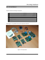
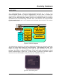
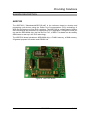
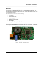
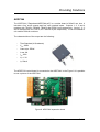
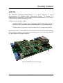
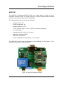
Providing Solutions
ADD
PLC STARTER KIT User Manual
V1.02
ADD PLC STARTER KIT User Manual
05/06/2007
1 of 12
Providing Solutions
INTRODUCTION
ADVANCED DIGITAL DESIGN has developed this PLC STARTER KIT to allow the
user to start up in the PLC technology and routing configuration. ADD can supply also
reference designs, application notes, embedded communication stack software
(ECSS), developing tools and controls and monitoring software. The ECSS (“\User
Manuals\ECSS User Manual.pdf”) includes advanced functions such as routing and
multi application support.
PLC Starter Kit contains 7 devices based on ADD1000A chip. This chip includes
80C51 microcontroller and MAC (Medium Access Control). With this Kit, you can
develop your own communications library, but ADD recommends to use our embedded
communication stack software (ECSS).
The embedded communication stack software (ECSS) provides to developers an easy
to use and stable application program interface (API) to develop applications using
PLC technology. ECSS is supported by ADD, free of cost, and with it you will be able to
use our development tools and reference designs. The devices designed using ECSS
can interoperate with devices of other manufactures in an open multi-manufacturer
environment in applications such as home automation, industrial control or automatic
meter reading (AMR) and energy management (AMM). These devices are also
supported by the monitoring and control software provided by ADD.
In addition, with this Kit, example tests are included to make programmer’s task easier.
They are simple examples covering concepts such as loading programs, controlling
ports and timers on 8051 microcontroller, communication between devices and routing
configuration (see Tests section).
The ADD1000A includes additional features such as auto load program from serial
flash and Inboard serial flash programming. Using these features the program to be run
by the microcontroller is stored in the flash memory of ADD7232 board. When power is
supplied to the board, program is loaded on the bottom half of external RAM. Two ways
can be followed to change contents in the flash memory:
1. Inboard serial flash programming; Connecting the device to the PC’s serial
port and use ADD6030 application to load the program on it (see “\Application
Notes\APN100 How to Program the ADD7232.pdf”)
2. Remote firmware upgrade; Loading the program on already installed devices,
through ECSS network
PLC STARTER KIT allows to evaluate all the features of ECSS (routing, multi
application, multi medium messy network). It includes full documentation of ECSS,
design references, development, configuration and monitoring tools and the following
boards:
1 ADD7260
2 ADD7281
2 ADD7251
2 ADD7244
9 ADD7232
three-phase concentrator.
expansion board 1 ON/OFF output + RS232
expansion board 1 dimmer output + 1 opto coupled input
expansion board 4 ON/OFF output + 4 opto coupled input
to control the previous boards
ADD PLC STARTER KIT User Manual
05/06/2007
2 of 12
Providing Solutions
BILL OF MATERIALS
This kit includes the following components:
1
2
3
4
5
6
7
8
9
Two electronic devices that consist of ADD7232 connected to a ADD7251
Two electronic devices that consist of ADD7232 connected to a ADD7244
Two electronic devices that consist of ADD7232 connected to a ADD7281
A electronic device that consist of 3 ADD7232 connected to a ADD7260
Two serial wires
Four jumpers
Connectors
A RJ-45 to RS-232 adapter
CD-ROM
In the Figure 3 it is possible to see each component of the KIT
Figure 3. Kit components
ADD PLC STARTER KIT User Manual
05/06/2007
3 of 12
Providing Solutions
ADD1000A
The ADD1000AQF128 (“\Datasheets\ADD1000AQF128.pdf”) is a Power Line
Communications System on Chip, it implements a full PLC node. It includes an
enhanced 8051 microcontroller (IP core ADD8051C12A), a Medium Access Controller
(MAC) (IP core ADD1200) and a Modem circuit for the EHS/KNX Power Line medium
specifications (IP core ADD1300). The MAC acts as link between the microcontroller
and the modem, but it can be set in bypass mode allowing direct control of the modem
by the microcontroller.
AC Line
ADD1000: SoC solution
Single
Single3.3V
3.3V
Power
PowerSupply
Supply
power
power
driver
driver
SPI
SPIFLASH
FLASH
SRAM
SRAM
ADD8051
Power
Driver
Analog
Front End
ADD1300
ADD1300
Control Register
4DIMMER
SFR
TIMER
UART
RAM
ADD1200
ADD1200
ROM
ROM
Figure 4. ADD1000 diagram
The ADD1000 is designed to be used by OEM and provides a low cost and small size
solution for narrow band power line communications. ADD1000AQF128 uses 0.35u
CMOS 3.3v supply, and is packed in a thin quad flat pack 128 leads, 0.4 mm pitch,
package, this allows a reduced PCB area (16x16 mm) while maintaining a good
thermal characteristics (Tja=41ºC/w). It can be used in continuous emission against
short-circuit in an 85ºC ambient. Up to 24 ports are available to the user.
Figure 5. ADD1000A photo
ADD PLC STARTER KIT User Manual
05/06/2007
4 of 12
Providing Solutions
BOARDS DESCRIPTION
ADD7232
The ADD7232 (“\Datasheets\ADD7232.pdf”) is the reference board to develop and
prototyping new devices using the Power Line Communication (PLC) technology of
ADD and its System on Chip (SoC) solutions. The ADD7232 is a small board of 4x4cm
size including all the electronics to implement a PLC application. Using this board you
can test the ADD1000A chip, the first SoC for PLC, of ADD. This board can be used by
OEM users to start up in the PLC technology.
The ADD7232 board includes an ADD1000A chip, a FLASH memory, a RAM memory,
22 general purpose I/Os and a serial RS232 link.
Figure 6. ADD7232 board
ADD PLC STARTER KIT User Manual
05/06/2007
5 of 12
Providing Solutions
ADD7251
The ADD7251 (“\Datasheets\ADD7251.pdf”) is a mother board of 80x52 mm size. It
includes a dimmer output and a opto coupled input. TRIAC3 pin matches the triac, and
P45 pin matches the input.
The characteristics of the output are the following
-
Type: Gated
-
Voltage-Rated: 600V
-
Current rating: 8A
-
Package: D2Pak (TO-263)
-
Non-Isolated
-
Average Power Dissipation: 500mW
The ADD7232 control board is connected to the ADD7251. In the Figure 7 it is possible
to see a picture of the ADD7251
Figure 7. ADD7251 expansion board
ADD PLC STARTER KIT User Manual
05/06/2007
6 of 12
Providing Solutions
ADD7244
The ADD7244 (“\Datasheets\ADD7244.pdf”) is a mother board of 82x63 mm size. It
includes a four on/off outputs and four opto coupled inputs. Outputs 1, 2, 3 and 4
matches with TRIAC1, TRIAC0, TRIAC2 and TRIAC3 pins respectively. Inputs 1, 2, 3
and 4 matches with INT3, INT2, INT1 and INT0 pins respectively. It can be installed in
a 4 module DIN-rail enclosure.
The characteristics of the output are the following:
-
Triac Standard (4 Quadrants)
-
Vdrm: 600V
-
Case style: DPAK
-
It rms: 8A
-
Itsm: 80A
-
Vgt: 1.3V
-
Igt: 50mA
The ADD7232 control board is connected to the ADD7244. In the Figure 8 it is possible
to see a picture of the ADD7244
Figure 8. ADD7244 expansion board
ADD PLC STARTER KIT User Manual
05/06/2007
7 of 12
Providing Solutions
ADD7260
The ADD7260 (“\Datasheets\ADD7260.pdf”) is a device designed to extend
communication to a triphase system (three-phase coupler).
It consists of a
motherboard and three ADD7232 (one board for every electrical phase). Also, it has a
RJ-45 connector, used to connect it to a PC.
It mainly has two operation modes:
- Triphase repeater: it takes care of detecting frames which does not get a
connection with a destination node, and repeating them through three phases.
- Triphase emitter: it can send a received frame from PC through three phases.
No serial port lines of three ADD7232 are connected to the RJ-45 connector directly.
This connector is shared. So to send a serial frame to PC, first of all each ADD7232
can take charge of the global serial port.
Figure 9. ADD7260 expansion board
ADD PLC STARTER KIT User Manual
05/06/2007
8 of 12
Providing Solutions
ADD7281
The ADD7281 (“\Datasheets\ADD7281.pdf”) is a mother board of 10x8 cm size. It
includes a serial port output, an output relay (PCH-112D2H), and three leds connected
to 80c51 microcontroller ports (P41, P44 and P45)
The characteristics of the output are the following:
-
Voltage coil DC: 12V
-
Current contact max: 5A
-
Voltage contact AC: 277V
-
1 Form A (SPST-NO) or 1 Form C (SPDT) contact arrangements.
-
5 or 10A ratings.
-
Compact size 20L x 10W x 15.2H (mm).
-
High surge voltage of 8000V.
-
Cadmium-free contacts.
-
Sensitive (200mW) coil available on 1 Form A types.
The ADD7232 control board is connected to the ADD7281. In the Figure 10 it is
possible to see a picture of the ADD7281
Figure 10. ADD7281 expansion board
ADD PLC STARTER KIT User Manual
05/06/2007
9 of 12
Providing Solutions
SOFTWARE DEVELOPING
INTRODUCTION
Advanced Digital Design provides in this kit c libraries to develop any application based
on PLC comunication. Also, 7 tests are included in the CD in order to help
programmers work easier (see tests section). Each device has a house address (2
bytes), an individual address (1 byte) and a group address (1 byte). To send a PLC
frame, it is needed to indicate which port (2 bytes) is used (see “\User Manuals\ECSS
User Manual.pdf”)
ADD provides the following libraries to develop your own applications:
-
lib_timer.h: controls microcontroller timings
lib_serial.h: configures serial port and contains the functions to manage it
lib_ecss.h: communication library
lib_module.h: functions to manage numbers and types
lib_developer.c and lib_developer.h: library where programmers can include
their own functions.
Main.c: contains main functions
EMBEDDED COMMUNICATION STACK SOFTWARE (ECSS)
To send commands on different protocols (PC, RF, Internet, GPRS…), and from
different access points, addressing ports are used, as TCP/IP does. Each device has a
3 byte address, so addressing range is 16M. Advanced Digital Design has reserved
some ports (FF00-FFFF) for its own protocols. The steps to send a frame to another
device are the following:
1. Initialize the PLC library (IniNET() function)
2. Assign an address (SET function)
3. Open a session (OPEN function). This function needs as parameters the
destination address, and the port they are going to use. A node can only keep
8 ports opened at the same time. If communication with the other device fails,
or the node is using more than 8 different ports, the session will not be opened.
If the session has been opened correctly:
4. Fill the vector to send (txdatosPLC[ ])
5. Send the frame (PUT function)
A full description of the embedded communication stack software (ECSS) can be found
in “\User Manuals\ECSS User Manual.pdf”
ADD PLC STARTER KIT User Manual
05/06/2007
10 of 12
Providing Solutions
TESTS
TEST 1: Loading and running a simple program
Test 1 aim is the load, compilation and execution of a simple program on 80C51
microcontroller integrated on ADD7232 board. Once the program is loaded onto
the device, open CRT Terminal. If a number is pressed, yellow led switches, if a
lower case letter is pressed, green led switches, and if an upper case letter is
pressed, red led switches. See “\Application Notes\APN102 Test1.pdf”
TEST 2: Port and timing control of 80C51
Test 2 aim is controlling different ports on 80C51 microcontroller, switching them at
a constant time interval, using Timer0. Ports used are connected to leds and to
relay output on ADD7281 motherboard. When the program is running, a series of
switchings on leds and relay can be seen. Every second, one of them switches.
See “\Application Notes\APN103 Test2.pdf”
TEST 3: Port control of 80c51 through serial port
Test 3 aim is controlling different ports on 80C51 microcontroller and switching
them according to received characters through serial port. ADD7281 board
includes 3 leds, green, yellow and red (P45, P41 and P44 ports respectively), and
a relay (P47 port). For more information see Boards description section. In this
test, some keys are related to the leds and the relay. If ‘g’ key is pressed, green
led switches. Likewise, with ‘y’ key, yellow led switches, with ‘r’ key, red led
switches, and with ‘R’ key, the relay switches. “\Application Notes\APN104
Test3.pdf”
TEST 4: Port control of 80c51 through PLC communication
Test 4 aim is controlling different ports on 80C51 microcontroller, switching them
according to received frames by PLC. In this test, some keys are related to remote
leds and relay. If ‘g’ key is pressed, remote green led switches. Likewise, with ‘y’
key, remote yellow led switches, with ‘r’ key, remote red led switches, and with ‘R’
key, the remote relay switches. “\Application Notes\APN105 Test4.pdf”
ADD PLC STARTER KIT User Manual
05/06/2007
11 of 12
Providing Solutions
TEST 5: Chat room through power line
Test 5 aim is implementing a Chat through the PLC Network. Anything written from
one device is sent to the other once the user presses Enter key and vice versa.
See “\Application Notes\APN106 Test5.pdf”
TEST 6: Complete test with a windows application
With test 6, you can open and close sessions, set the device address, send frames
to any device, write and read memory flash, switch remote leds and relay, and
send a character string. It comes with a simple windows application to show the
test operation. See “\Application Notes\APN107 Test6.pdf” and “\Application
Notes\APN108 Test6 Windows Application.pdf”
TEST 7: Routing configuration
This test is intended to demonstrate how Routing technologies can improve
robustness in a PLC Network, by means of providing alternative routes (or paths)
to reach nodes which otherwise will not be seen from any device inside the
network. In this document you will find a step by step procedure aimed to learn
how to use routing in an ADD network. See “\Application Notes\APN111
Test7.pdf”
ADD PLC STARTER KIT User Manual
05/06/2007
12 of 12