1
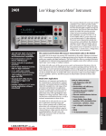
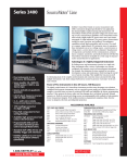
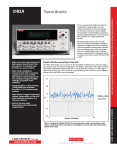
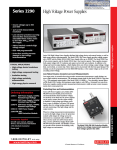
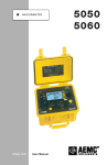
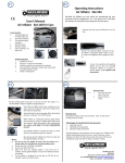
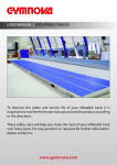
99 Washington Street
Melrose, MA 02176
Phone 781-665-1400
Toll Free 1-800-517-8431
2790
Visit us at www.TestEquipmentDepot.com
SourceMeter Airbag Test System
The Model 2790 SourceMeter Switch System is a high voltage, multichannel resistance measurement solution that speeds and simplifies electrical
checks of airbag inflators and a variety of other automotive electrical
test applications. It is the only commercial instrument that combines all
the sourcing, measurement, and signal routing capabilities required to
measure insulation resistance and conductor continuity in one compact,
affordable package. Through the use of plug-in source/switch modules, the
Model 2790 provides programmable high voltage and low current sourcing, plus multichannel switching support. This unique combination of
capabilities establishes a new standard for price and performance in airbag
inflator and other test applications.
Measure Extreme Resistances with
Constant Current or Constant Voltage
The Model 2790 uses the forced constant-current method to measure resistances less than 1kΩ. In this technique, the instrument sources a constant
current (I) to the resistance and measures the resulting voltage (V). The
amount of current sourced is programmable from 0–50mA. Resistance (R)
is calculated (and displayed) using the known current and measured voltage (R = V/I). A 20mV dry circuit clamp is available at sourcing levels up to
1mA for preserving the oxide layers on connectors and other components.
• Single-instrument solution for
continuity and hi-pot type leakage
resistance measurements
• Programmable constant V source
(50–500V) supports high speed,
high resistance measurements
• Programmable constant I source
(0–50mA) with dry circuit clamp
helps prevent device stress or
damage during low resistance
measurements
• Modular architecture adapts easily
to single or dual inflator testing
and to single or dual position test
stands and mixed device/signal
applications
DIGITAL MULTIMETERS & SYSTEMS
• Expandable multiplexer channels
for multipin applications
• Included 6½-digit DMM with
wide functionality and broad
measurement ranges
• Intelligent automation support and
easy integration with external test
hardware
• GPIB, RS-232, and digital I/O
interfaces for flexible controller
options
• SCPI programmable for simple code
development and future extensions
For the 1MΩ to 1GΩ resistance ranges, the forced constant-voltage method
is used to measure high resistance. This technique optimizes settling speed
and reduces noise, allowing faster, high quality insulation resistance measurements. In addition, by
applying high voltages (50–500V), the Model 2790 stresses a dielectric while simultaneously measuring its insulation resistance.
In addition to the resistance measurement functions available through the plug-in source/switch
modules, the Model 2790’s built-in DMM allows it to make a full range of high precision resistance
measurements as well as AC/DC voltage and current, frequency, and temperature measurements.
These DMM functions are available either through front panel jacks or through the addition of a
Model 7702 40-channel scanner module. In addition to the shorts/open testing performed with the
standard Model 7751, 7752, and 7753 switch/
control modules, a wide range of supporting
APPLICATIONS
measurements can be made. These support• Automotive airbag inflator/
ing measurements simplify creating integrated
module electrical functional tests
test solutions for hybrid applications, such as
testing complex automotive seating systems,
• Seatbelt pre-tensioner actuator/
which increasingly combine airbag inflators and
module functional electrical check
seatbelt pre-tensioners, seat heaters, switches,
• High speed, parallel soak, dual
motors, etc.
Newly Enhanced Memory
Pattern Test Sequencer
The memory pattern test sequencer allows
the mainframe to store and execute preprogrammed test sequences for increased testing
throughput. Test setups can be stored as unique
memory locations and either recalled by number
as needed or scanned in sequence to maximize
the number of tests per unit time without command transfer delays due to communication or
controller.
• 2-year calibration cycle of modules
minimizes maintenance costs and
system downtime
inflator, or dual test station
electrical check
• Pinched wire, high voltage,
insulation resistance testing in
automotive seats, avionics, etc.
• Multipin connector/harness
continuity and leakage resistance
measurements
• Multicontact/switch dry circuit
continuity and leakage tests
• Automotive power/fuse center
continuity and leakage resistance
characterization
• PCB/PWB and general purpose
short/open circuits testing
A
G R E A T E R
M E A S U R E
O F
C O N F I D E N C E
Multichannel resistance measurements for airbag inflator, harness, and connector testing
Multichannel resistance measurements for airbag inflator, harness, and connector testing
®
2790-A 1MΩ single-module
system for low and high
voltage/resistance applications
2790-H Single-module system
for low and high voltage/
resistance applications
2790-HH Two-module system
for low and high voltage/
resistance applications
2790-HL Two-module system
for separating high and low
voltage/resistance applications
2790-L Single-module system
for low voltage/resistanceonly programmable
current applications
7702 40-channel Differential
Multiplexer
Accessories Supplied
Reference and user manuals on
CD-ROM, AC line power cord, mini
flathead screwdriver.
ACCESSORIES AVAILABLE
MODULES
7702
7751
7752
7753
40-channel General Purpose Multiplexer Module
High Voltage Source/Switch Module
Low Voltage, Current-Source-Only Source/Switch
Module
1MΩ High Voltage Source/Switch Module
(The Model 2790 supports only one Model 7753.)
COMMUNICATION INTERFACES AND CABLES
7007-1
7007-2
7009-5
KPCI-488LPA
KUSB-488B
Shielded IEEE-488 Cable, 1m (3.3 ft.)
Shielded IEEE-488 Cable, 2m (6.6 ft.)
Shielded RS-232 Cable
IEEE-488 Interface/Controller for the PCI Bus
IEEE-488 USB-to-GPIB Interface Adapter
RACK MOUNT KITS
4288-1, -2
Single or Dual Fixed Rack Mount Kit
OTHER
8503
8681
Trigger Link Cable to 2 Male BNC Connector
Miniature 4-Wire RTD, 100Ω
SERVICES AVAILABLE
2790-3Y-EW
1-year factory warranty extended to 3 years
from date of shipment
2790-A-3Y-EW
1-year factory warranty extended to 3 years
from date of shipment
2790-L-3Y-EW
1-year factory warranty extended to 3 years
from date of shipment
C/2790-3Y-ISO 3 (ISO-17025 accredited) calibrations within 3
years of purchase for Models 2790, 2790-L*
C/2790-A-3Y-ISO 3 (ISO-17025 accredited) calibrations within 3
years of purchase for Model 2790-A*
*Not available in all countries
SourceMeter Airbag Test System
Match the System Configuration to the Application
The Model 2790 is available in a variety of configurations to match specific application requirements:
• The Model 2790-H is a single-module system designed for both low current and high voltage
ohms (10MΩ to 1GΩ) applications. This “base” system provides all the capabilities needed for
electrical testing of either single- or dual-stage inflators in single position test stands (for example,
test stands that test only one single- or dual-stage airbag at a time).
• The Model 2790-A, which is similar to the Model 2790-H, enables high voltage ohms measurements down to 1MΩ.
• The Model 2790-HH is configured for applications that require parallel testing or high voltage
“soaking.” Like the Model 2790-H, it is designed for both low current and high voltage ohms applications and can test either single- or dual-stage inflators. However, with two plug-in modules, it
also has the capacity to test two inflators at once, maximizing test throughput.
• The Model 2790-HL is designed for applications where it is preferable to segregate high voltage
sourcing/ohms measurement and low current sourcing/ohms measurement into two separate
modules. This design was developed for use in combination testing applications, such as inflator
electrical checks of safety steering wheel or seat assemblies that also include switch or other ancillary device tests.
• The Model 2790-L is configured for low voltage source/ohms-only measurement applications,
such as continuity-only testing of side/seat airbags and seatbelt pre-tensioners or other programmable I-source resistance applications in which high voltage resistance testing is not required but
precise control of source current is.
• With the addition of a Model 7702 40-channel differential multiplexer module (part of the Integra
family of switch/measure solutions), the Model 2790-A, -H, or -L + Model 7702 opens the door
to higher channel count applications, such as hi-pot/continuity testing of connectors, harnesses,
and power distribution devices up to 500V (internally sourced) up to 40 channels.
Broad Range of Measurement Capabilities
The Model 2790’s built-in DMM can make a wide variety of general purpose measurements:
• DC voltage measurements from 0.1µV to 1000V
• AC voltage measurements from 0.1µV to 750V
• DC current measurements from 10nA to 3A
• AC current measurements from 1µA to 3A
• 2-wire resistance measurements from 100µΩ to 120MΩ
• 4-wire resistance measurements from 100µΩ to 120MΩ
• Frequency measurements from 3Hz to 500kHz
• Period measurements from 333ms to 2µs
• Temperature measurements from –200°C to 630°C (thermistors and 4-wire RTDs)
Additional features of the Model 2790 mainframe include:
• Setup storage—Up to four instrument setups can be saved and recalled.
• Offset-compensated ohms—A two-measurement process for 4-wire ohms to cancel the effects of
thermoelectric EMFs. Available for the 100Ω, 1kΩ, and 10kΩ ranges.
• Math—m/X+b, mX+b, percent, and four special math functions provide convenient manipulation
of raw readings.
• Relative—Null offsets establish baseline values.
• Ratio and channel average—Ratio and average calculations for two switching module channels (7702).
• Buffer—Store up to 55,000 readings in the internal buffer.
• Limits—Two sets of high and low reading limits to test devices.
• Digital I/O port—Five digital limit test output lines to control external circuitry. An external trigger
input can also be accessed at this port.
• Trigger Link—Separate connector with input and output signals.
• Monitor—The Model 2790 can monitor a selected channel. A scan can be triggered to start when
the monitor detects that a reading limit has been reached (7702).
• Remote interface—Model 2790 can be controlled using the IEEE-488 interface (GPIB) or the
RS-232 interface.
A
G R E A T E R
M E A S U R E
O F
C O N F I D E N C E
Multichannel resistance measurements for airbag inflator, harness, and connector testing
Ordering Information
®
DIGITAL MULTIMETERS & SYSTEMS
Multichannel resistance measurements for airbag inflator, harness, and connector testing
2790
®
Multichannel resistance measurements for airbag inflator, harness, and connector testing
Example Application – Dual Stage Airbag Inflator Testing–One or Two
Model 2790 Benefits
• High functional integration—Sourcing,
measurement, and signal routing functions
are tightly integrated in one compact
enclosure. This high level of integration
helps system integrators save rack space,
minimize the time needed for system
configuration and maintenance, and
improve test throughput without sacrificing
system accuracy.
• Enhanced device protection—Compared
to higher powered alternatives, the Model
2790’s inherently lower power sources
minimize the possibility of damaging
sensitive devices under test through
accidental overpowering. Automatic cold
switching and active cable discharge
circuitry reduce the chances for device
damage still further, while the high
precision DMM and A/D converter ensure
high resolution and measurement accuracy.
• Reliability—The design of the Model 2790
is based on a proven Keithley technology
platform. With a two-year calibration
cycle for the module functions, it requires
minimal maintenance over the life of the
production test line. Its modular mainframe
and plug-ins architecture makes module
verification and calibration fast and
convenient, simply by exchanging modules.
• Value—In addition to being a complete
solution for airbag inflator testing and
related applications, the Model 2790’s fully
functional, 6½-digit DMM supports a wide
variety of general purpose DC and AC
measurements.
2790 Mainframe
7751/7752/7753 Source/Switch Module
Dual Inflator 1
2
High Voltage
Sour ce
(deleted in 7752)
DUT A
DUT B
4
4
CPU
Low Ohms Meter
A/D Converter
Interfaces
Digital I/O
Power Supply
Programmable
Curr ent Sour ce
0–50mA
Relay
Matrix
Dual Inflator 2
D
A
Contr ol Logic
Analog Signal
Conditioning
DUT A
DUT B
Optional 2nd Module
Example Application – 40-channel Wiring Harness Testing
2790 Mainframe
7751/7752/7753 Source/Switch Module
7702 MUX Card
DUT
High Voltage
Source
(7751 or 7753)
CPU
Low Ohms Meter
A/D Converter
Interfaces
Digital I/O
Power Supply
Relay
Matrix
Programmable
Current Source
0–50mA
Control Logic
Analog Signal
Conditioning
DIGITAL MULTIMETERS & SYSTEMS
Mainframe Specifications
Refer to the Model 2700 specifications on page 253.
Three source/switch plug-in modules provide the Model 2790 with
programmable high voltage and
low current sources, connection
switching, and signal conditioning
circuitry.
Key Module Specifications*
Refer to module specifications on page 257.
SYSTEM THROUGHPUT
HIGH OHMS: 13 rdgs/s.
LOW OHMS: 9 rdgs/s.
* The Model 7751, 7752, and 7753 plug-in modules have a two-year
calibration interval; mainframe-only functions have a one-year
calibration interval (max). System warranty period is one year.
A
G R E A T E R
M E A S U R E
O F
C O N F I D E N C E
Test Equipment Depot - 800.517.8431 - 99 Washington Street Melrose, MA 02176
TestEquipmentDepot.com
Multichannel resistance measurements for airbag inflator, harness, and connector testing
SourceMeter Airbag Test System
2790
®
SourceMeter Airbag Test System
2790
CURRENT MEASURE INPUT (7751/7753 Only)
(Module function accuracy specifications are for 2 years, 23°C, ±5°C.)
TypIcal
Temperature
Open
Coefficient
Source
Maximum
Circuit
Accuracy (4W) (0–18°C & 28–40°C)
Current
Resistance
Voltage
±(%rdg.+ohms) ±(%rdg.+ohms)/°C
50 mA
20
5.5 V
0.09% + 2 m
0.002% + 3 m
20 mA
50
5.5 V
0.11% + 5 m
0.003% + 3 m
10 mA
100
5.5 V
0.16% + 10 m
0.004% + 3 m
(Dry Circuit Ohms 1mA max. with 7751, 7752, or 7753 card)
1 mA
10
20 mV
1.10% + 50 m
(0.026% + 3 m)/°C
RANGE: 7751: 0–50µA. 7753: 0–500µA.
ACCURACY: 7751: ±(0.5% of reading + 6nA) (2 year specification).
7753: ±(0.5% of reading + 60nA) (2 year specification).
TEMPERATURE COEFFICIENT (0–18°C & 28–40°C): ±(0.02%+0.5nA)/°C.
VOLTAGE BURDEN: <1mV.
Resistance
Range
10 M
100 M
1G
1M
10 M
100 M
MaxImum
Short
Circuit
Current
<1 mA
<1 mA
<1 mA
<1 mA
<1 mA
<1 mA
Resistance
Range
1M
10 M
100 M
1G
0.1 M
1M
10 M
100 M
MaxImum
Short
Circuit
Current
<1 mA
<1 mA
<1 mA
<1 mA
<1 mA
<1 mA
<1 mA
<1 mA
(7751 Only)
Source
Voltage
500 V
500 V
500 V
50 V
50 V
50 V
(7753 Only)
Source
Voltage
500 V
500 V
500 V
500 V
50 V
50 V
50 V
50 V
Accuracy
±(% rdg.)
0.8%
1.1%
4.0%
1.1%
1.1%
1.6%
Temperature
Coefficient
(0–18°C & 28–40°C)
±(%rdg.)/°C
0.03%
0.05%
0.12%
0.04%
0.06%
0.13%
Accuracy
±(% rdg.)
0.8%
0.9%
1.3%
6.7%
1.1%
1.1%
1.3%
4.5%
Temperature
Coefficient
(0–18°C & 28–40°C)
±(%rdg.)/°C
0.02%
0.03%
0.10%
0.27%
0.03%
0.04%
0.11%
0.30%
SWITCHING CAPABILITIES (Bank 1–Bank 4)
4 CHANNELS: 1 Form A switch.
8 CHANNELS: Four 4-pole or eight 2-pole signals into DMM or I/V converter.
CONTACT CHECK: 4-wire contact check through internal DMM.
RELAY TYPE: Latching electromechanical.
ACTUATION TIME: <3ms.
CONTACT LIFE (typical):>106 operations at maximum source level.
>108 operations cold switching.
CONTACT RESISTANCE: <1Ω at end of contact life.
CONTACT POTENTIAL: <±2µV typical per contact pair, ±3µV max.
CONNECTOR TYPE: Plugable screw terminal, #22 AWG wire size.
ISOLATION BETWEEN ANY TWO TERMINALS1: >1GΩ, <100pF.
ISOLATION BETWEEN TERMINALS AND EARTH1: >1GΩ, <200pF.
ISOLATION BETWEEN CHANNEL GROUPS1: >500GΩ, <100pF.
EXTERNAL COMMON MODE VOLTAGE: 42V between any terminal and chassis. (Connect no
external sources.)
7751, 7752, OR 7753 MODULE NOTES
Model 7751/7752/7753 specifications
2790 RESISTANCE MODE SPECIFICATIONS WITH CARDS 2, 3
1 Isolation for channels 1–12, only one channel closed at a time, or all channels open.
2 See User's Manual for ohm specifications at sources other than those specified.
3 All specifications valid for 1 NPLC ADC aperture setting.
SYSTEM THROUGHPUT
(Connect, source, measure, calculate)
0.01 NPLC, FILTER OFF, OVER GPIB BUS: High Ohms (Source V): 13 rdgs/s1.
Low Ohms (Source I): 9 rdgs/s.
1 NPLC, FILTER ON, OVER GPIB BUS:
High Ohms (Source V): 11 rdgs/s1.
Low Ohms (Source I): 7 rdgs/s.
CURRENT SOURCE OUTPUT
OUTPUT LEVEL: Programmable 0 to 50mA (Ch. 27).
PROGRAMMING RESOLUTION: 10µA.
OUTPUT VOLTAGE: 5.5V ±10% compliance.
ACCURACY: ±(0.06% + 10µA) (2 year specification).
SETTLING TIME: 1ms to 0.1% of final value (typ.).
TEMPERATURE COEFFICIENT (0–18°C & 28–40°C): ±(0.001% + 0.25µA)/°C.
DRY CIRCUIT CLAMP (Ch. 24): 20mV ±10%, Isource ≤1mA.
SYSTEM THROUGHPUT NOTES
1. Reset upon fixed Vsource level, no settling time.
BASIC AIRBAG TEST SEQUENCE THROUGHPUT
(Body Pin + Bridgewire Continuity = Shorting Clip + Insulation Resistance)
0.55/0.97 seconds for single/dual stage DUT w/scan (sequential) memory patterns.
1.0/2.0 seconds for single/dual stage DUT w/recall (random access) memory patterns.
1.1/1.7 seconds for single/dual stage DUT discrete control w/GPIB I/O.
(Sequence times are totals @ 1 line cycle integration for rated accuracy.)
VOLTAGE SOURCE OUTPUT (7751/7753 Only)
OUTPUT LEVEL: Programmable 50V to 500V (Ch. 28).
PROGRAMMING RESOLUTION: 100mV.
OUTPUT CURRENT: (7751) 50µA maximum for rated accuracy, <1mA typical into short circuit.
(7753) 500µA maximum for rated accuracy, <1mA typical into short circuit.
ACCURACY: ±(0.5% + 0.13V) (2 year specification).
SETTLING TIME: Rise Time: 50V to 500V step, 0.1% of final value, 250ms max.
Fall Time: 500V to 50V step, 0.1% of final value, 1000ms max.
TEMPERATURE COEFFICIENT (0–18°C & 28–40°C): ±(0.001% + 0.005V)/°C
SAFETY LIMIT: Current limited maximum current of 1mA.
CABLE DISCHARGE (Ch. 20): 100kΩ shunt.
MAXIMUM CAPACITANCE: 1nF.
A
G R E A T E R
M E A S U R E
O F
C O N F I D E N C E
DIGITAL MULTIMETERS & SYSTEMS
Model 7751/7752/7753 specifications
7751/7752/7753 SOURCE/SWITCH MODULE SPECIFICATIONS
®
SourceMeter Airbag Test System
2790
Ch. 25
Ch. 13
Model 7751/7752/7753 specifications
Bank 1
J101
LO
Source
Sense
Source
Sense
A1
B1
Ch. 15
Ch. 2
Ch. 16
Ch. 18
Ch. 3
Ch. 17
Ch. 19
Source Enable
HI
Bank 2
J102
LO
Source
Sense
Source
Sense
A2
B2
HI
Bank 3
J103
LO
Source
Sense
Source
Sense
A3
B3
HI
Bank 4
J104
LO
Source
Sense
Source
Sense
A4
B4
DIGITAL MULTIMETERS & SYSTEMS
Ch. 14
Ch. 1
+5V
Ch. 4
10K
Ch. 5
HI
LO
HI
Input
Sense
LO
Interlock
+5V
J106
Interlock
Guard
Guard
Source HI
Ch. 6
Source LO
J105
Sense HI
Ch. 7
Sense LO
I/V In
Ch. 8
I/V Out
J108
I/V LO
Ch. 9
Vsrc HI
Vsrc LO
Ch. 10
Isrc HI
10K
Ch. 11
Isrc LO
J107
Guard
Guard
Ch. 12
Vsource Ch. 28
(7751 & 7753 only)
–
Ch. 23
50–
500V
To
Model 2790
Backplane
+
+
–
Ch. 20
100kΩ
I/V Current/ Voltage
Amplifier
(7751 & 7753 only)
Cable Discharge
(7751 & 7753 only)
0–
50mA
Ch. 24
20mV
Dry
Ckt
Isource Ch. 27
1Ω
Ch. 22
Ch. 21
Ch. 22 Open: Isource Select
Ch. 22 Close: Vsource Select
A
G R E A T E R
M E A S U R E
O F
C O N F I D E N C E
Test Equipment Depot - 800.517.8431 - 99 Washington Street Melrose, MA 02176
TestEquipmentDepot.com
Model 7751/7752/7753 specifications
HI