1
INSTALLATION GUIDE
PELLET BOILER
LOGIKA 25-35
LOGIKA 25-35 REFILL
PART 1 - ASSEMBLY
Translation of the original instructions
GB
TABLE OF CONTENTS
TABLE OF CONTENTS....................................................................................... II
INTRODUCTION .............................................................................................. 1
1-WARNINGS AND WARRANTY CONDITIONS. . ..................................................... 2
2-INSTALLATION INSTRUCTIONS...................................................................... 6
3-DRAWINGS AND TECHNICAL CHARACTERISTICS..............................................14
4 - UNPACKING.............................................................................................18
5 - POSITIONING...........................................................................................22
6 - INSTALLATION AND ASSEMBLY OF BOILER. . ..................................................24
7 - INSTALLATION AND ASSEMBLY OF TANK. . .....................................................46
8 - ASSEMBLY OF BOILER AESTHETICS UNIT .....................................................58
9 - ASSEMBLY OF TROLLEY. . ............................................................................63
10 - ASSEMBLY OF AESTHETICS UNIT OF REFILL TANK.. .......................................65
11 - ASSEMBLY OF AESTHETICS UNIT OF MANUAL TANK......................................71
II
INTRODUCTION
Dear Customer,
Thank you for having chosen our product.
In order to make the most of this product and ensure its maximum efficiency, you are advised to read this manual carefully
before initial use.
REVISIONS TO THE PUBLICATION
The content of this manual is strictly technical and the property of MCZ Group Spa.
No part of this manual can be translated into another language and/or altered and/or reproduced, even partially, in another form, by
mechanical or electronic means, photocopied, recorded or similar, without prior written approval from MCZ Group Spa.
The company reserves the right to make changes to the product at any time without prior notice. The proprietary company reserves its
rights according to the law.
CARE OF THE MANUAL AND HOW TO CONSULT IT
•
•
•
•
•
Take care of this manual and keep it in an easily accessible place.
Should the manual be misplaced or ruined, request a copy from your retailer or directly from the authorised Technical Assistance
Department.
The "text in bold" must be read with particular care.
The "text in italics" draws attention to other sections in this manual or clarifications.
“NOTE” provides the reader with additional information.
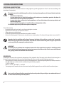
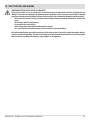
SYMBOLS USED IN THE MANUAL
ATTENTION:
Read the relative message with care because failure to observe the information provided could result in
serious damage to the product and danger to the persons who use it.
INFORMATION:
failure to comply with these provisions will compromise the use of the product.
OPERATING SEQUENCES:
sequence of buttons to be pressed to access the menus or make adjustments.
MANUAL
carefully read this manual or the relative instructions.
Technical Dept. - All rights reserved - Reproduction is prohibited
1
1-WARNINGS AND WARRANTY CONDITIONS
SAFETY PRECAUTIONS
• Installation, electrical connection, functional verification and maintenance must only be performed by qualified or
authorised personnel.
• Install the product in accordance with all the local and national laws and Standards applicable in the relative place,
region or country.
• This product is not intended for use by persons (including children) with reduced physical, sensory or mental
capabilities, or lack of experience and knowledge, unless they are supervised or trained on how to use the product by
a person responsible for their safety.
• Use only the type of fuel recommended by the firm. The product must not be used as an incinerator. It is strictly forbidden to use
liquid fuel.
• The instructions provided in this manual must always be complied with to ensure the product and any electronic appliances
connected to it are used correctly and accidents are prevented.
• The user, or whoever is operating the product, must read and fully understand the contents of this installation guide before
performing any operation. Errors or incorrect settings can cause hazardous conditions and/or poor operation.
• Do not put linen on the product to dry. Any clothes horses or similar objects must be kept at a safe distance from the product. Fire
hazard.
• All liability for improper use of the product is entirely borne by the user and relieves the Manufacturer from any civil and criminal
liability.
• Any type of tampering or unauthorised replacement with non-original spare parts could be hazardous for the operator's safety and
relieves the company from any civil and criminal liability.
• Most of the surfaces of the product can become extremely hot (the door, handle, flue pipes, etc.). Avoid touching these parts
without appropriate protective clothing or devices like heat insulated gloves.
• It is forbidden to use the product with its door open.
• The product must be powered by a system that is equipped with an effective earth system.
• Switch the product off in the event of a fault or malfunctioning.
• Do not wash the product with water. The water could get inside the unit and damage the electrical insulation and cause electric
shocks.
• Do not put any fuel other than wood pellets in the hopper.
• Install the product in rooms that are adequately protected against fire and equipped with all the utilities such as supplies (air and
electricity) and smoke outlets.
• In the event of fire in the chimney, turn off the device, disconnect it from the mains and do not open the hatch. Then contact the
competent authorities.
• It is recommended not to remove the feet that support the product in order to guarantee adequate insulation, especially if the
flooring is made of flammable material.
• If the ignition system is faulty, do not force ignition with flammable materials.
• Special maintenance must only be performed by authorised and qualified personnel.
• Assess the static conditions of the surface on which the weight of the product will rest and provide suitable insulation if it is made of
flammable material (e.g. wood, fitted carpet or plastic).
2
1-WARNINGS AND WARRANTY CONDITIONS
INFORMATION:
Please contact the retailer or qualified personnel authorised by the company to resolve a problem.
• only fuel stipulated by the company must be used.
• Check and clean the smoke outlet pipes regularly (connection to the chimney).
• Always keep the cover of the fuel hopper closed.
• Keep this instruction manual in a safe place, as it should accompany the stove along its entire life cycle. If it is sold or transferred to
another user, always make sure that the manual accompanies the product.
INTENDED USE
The product only works with wood pellets and must be installed indoors.
WARRANTY CONDITIONS
The firm guarantees the product, with the exception of parts subject to normal wear specified below, for two years from the date
of purchase, provided that proof of purchase is supplied in a document specifying the name of the retailer and the date the sale was made
and that the completed guarantee certificate was sent within 8 days of said purchase. The product must also be installed and tested by
a specialised fitter and in accordance with the detailed instructions provided in the instruction manual that accompanies the product.
The guarantee covers the replacement or free repair of parts recognised as being faulty at source due to manufacturing defects.
RESTRICTIONS
The guarantee does not cover parts subject to normal wear such as gaskets, glass, and any parts with can be removed from the firebox.
Replaced parts will be covered by the warranty for the remaining period of the warranty in force as from the date of purchase of the
product.
EXCLUSIONS
The warranty does not cover any part that may be faulty as a result of negligence or careless use, incorrect maintenance or installation that
does not comply with the company's instructions (see the relative chapters in this user manual).
The company declines all liability for any damage which may be caused, directly or indirectly, to persons, animals or objects as
a consequence of non compliance with all the prescriptions specified in the manual, especially warnings regarding installation,
use and maintenance of the appliance.
If the product does not work correctly, contact your local retailer and/or importer.
Damage caused during transport and/or when handled is excluded from the warranty.
The supplied installation guide is the only reference for installation and product use.
The warranty will be rendered null and void in the event of damage caused by tampering, atmospheric agents, natural disasters, electrical
discharges, fire, defects in the electrical system, and maintenance not being performed at all or as indicated by the manufacturer.
Technical Dept. - All rights reserved - Reproduction is prohibited
3
1-WARNINGS AND WARRANTY CONDITIONS
INTERVENTION REQUEST
The company declines all liability if the product and any other accessory is used incorrectly or altered without
authorisation.
All parts must be replaced with original spare parts.
The request must be sent to the retailer who will forward it to the Technical Assistance Department.
SPARE PARTS
Use only original spare parts. The retailer or service centre can provide all the useful information regarding spare parts.
It is recommended not to wait for the parts to be worn before having them replaced. It is important to perform regular maintenance.
PRECAUTIONS FOR CORRECT DISPOSAL OF THE PRODUCT IN ACCORDANCE WITH THE EUROPEAN DIRECTIVE
2002/96/EC AND ITS SUBSEQUENT AMENDMENT 2003/108 EC.
At the end of its working life, the product must not be disposed of as urban waste.
It must be taken to a special differentiated waste collection centre set up by the local authorities or to a retailer that provides this service.
Disposing of the product separately prevents possible negative consequences for the environment and health deriving from inappropriate
disposal and allows its materials to be recovered in order to obtain significant savings in energy and resources.
As a reminder of the need to dispose of appliances separately, the product is marked with a crossed-out wheeled dustbin.
4
1-WARNINGS AND WARRANTY CONDITIONS
RULES ON INSTALLATION
The product is a boiler that uses wood pellets.
It must be installed as per the following standards:
Legislative Decree no. 93 of 25 February 2000
Implementation of Directive 97/23/EC (PED) on pressure equipment.
FIELD OF APPLICATION: devices that use liquid fuels (naphtha, gas oil, fuel oil) and solids.
LAW NR. 46 of 5 March 1990 and relative applicable regulations, Presidential Decree 447 of 6 December 1991 (and subsequent
amendments) and M.D. 37 of 22 January 2008.
Rules on safety of the systems.
FIELD OF APPLICATION: with unlimited heat capacity.
Standard UNI 10847 of 03/2000.
Single flue systems for generators that use solid and liquid fuel. Maintenance and checks. Guidelines and procedures
FIELD OF APPLICATION: systems that use solid and liquid fuel.
LAW NR. 10 of 09 January 1991 and relative applicable regulations, Presidential Decree 412 of 26 August 1993 (and subsequent
amendments), Presidential Decree 551 of 21 December 1999.
Regulation implementing amendments to Presidential Decree 412 on the design, installation, use and maintenance of technical systems
of buildings for containing energy consumption.
FIELD OF APPLICATION: with unlimited heat capacity.
LAW 186 of 01.03.1968
Installation standard IEC 6408 / II ed.
Electrical systems with rated voltage not exceeding 1000 V AC and 1500 V DC.
Installation standard IEC 64-8 / I ed.
Electrical systems for residential buildings and similar.
Standard UNI 10683 of 09/2005.
Systems fuelled by wood or other solid biofuel.
Installation requirements.
FIELD OF APPLICATION: Systems fuelled by wood or other solid biofuel with heat output of the firebox of less than 35 kW.
Installation must be carried out with reference to the diagram of the heating system prepared in accordance with the
standards and local recommendations in force:
• For the heating system - EN 303-5 (September 2012) - Part 5: Heating boilers for solid fuels, manually and automatically stoked,
nominal heat output of up to 500 kW - Terminology, requirements, testing and marking
• Local requirements for connection to the chimney.
• Local requirements for fire-fighting standards.
• For electrical parts - EN 60335 "Safety of electrical household appliances and similar"
Part 1 - General requirements
Part 2 - Particular standards for appliances with gas, gas oil and solid fuel burners without electrical connections.
Technical Dept. - All rights reserved - Reproduction is prohibited
5
2-INSTALLATION INSTRUCTIONS
The requirements in this section relate to the provisions of the Italian standard of installation UNI 10683. In any case, always observe the
domestic rules in force.
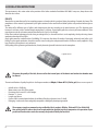
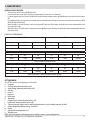
PELLETS
Wood pellets are manufactured by hot-extruding compressed sawdust which is produced during the working of natural dried wood. The
compactness of the material is guaranteed by the lignin contained in the wood itself and allows pellets to be produced without glue or
binders.
The market offers different types of pellets with characteristics that vary according to the wood mixtures used. The diameter varies
between 6 and 8 mm, with a standard length ranging from 5 to 30 mm. A good quality pellet has a density of between 600 and 750 or
more kg/metres cubed and a water content that accounts for 5 to 8% of its weight.
Pellets have technical advantages besides being an ecological fuel, as the wood residue is used completely, thereby achieving cleaner
combustion than that of fossil fuels.
Good-quality wood has a calorific value of 4.4 kW/kg (15% moisture, after about 18 months of seasoning), whereas that of pellets is 4.9
kW/kg. To ensure good combustion, the pellets must be stored in a dry place and protected from dirt. Pellets are usually supplied in 15 kg
bags, therefore, storing them is very convenient.
Good quality pellets guarantee good combustion, thereby decreasing harmful emissions into the atmosphere.
15 Kg BAGS OF FUEL
The poorer the quality of the fuel, the more often the internal parts of the brazier and combustion chamber must
be cleaned.
The main certifications of quality for pellets in the European market are DINplus, Ö-Norm M7135, Pellet gold; these ensure respect of:
•
•
•
•
•
•
•
calorific value: 4.9 kWh/kg.
Water content: max 10% of the weight.
Percentage of ash: max 0.5% of the weight.
Diameter: 5 – 6 mm.
Length: max 30 mm.
Content: 100% untreated wood without the addition of binding substances (max 5% bark).
Packaging: in sacks made from ecologically compatible or biologically decomposing material.
The company strongly recommends using certified fuel for its products (DINplus, Ö-Norm M7135 or Pellet Gold).
Poor quality pellets or others that do not comply with that specified previously compromises the operation of your
product and can therefore render the warranty and product liability null and void.
6
2-INSTALLATION INSTRUCTIONS
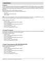
PRECAUTIONS REGARDING INSTALLATION
IMPORTANT!
Product installation and assembly must be carried out by qualified personnel.
The product must be installed in a suitable place for it to be regularly opened and routine maintenance to be performed.
The site must be:
• compliant for proper operation.
• Equipped with an adequate smoke expulsion system.
• Equipped with ventilation intake from outside.
• Equipped with 230V 50 Hz power supply with an EC compliant earth system.
The product must be connected to a chimney or vertical duct, either inside or outside, that conforms to the standards in
force. The product must be positioned in such a way that the electrical socket is accessible.
IMPORTANT!
The product must be connected to a chimney or a vertical duct that can expel the smoke at the highest point of the
building.
The fumes are however derived from the combustion of wood products, and if they come into contact with or close
to walls, they can make dirty marks. Moreover, utmost attention is required as they are almost invisible but very hot
and can cause burns. The holes of the external air inlet and the smoke outlet pipe must be drilled before positioning
the product.
THE OPERATING ENVIRONMENT
For correct operation and even distribution of heat, the product must be placed where the air required for combustion can flow.
The volume of the room should be no less than 15 m3
These openings (air inlets) must be made in such a way that it is impossible for them to be obstructed in any way.
The air can also be taken from rooms adjacent to the one which needs ventilating, as long as they are provided with an air intake from the
outside, and are not used as bedrooms or bathrooms, and provided there is no fire risk such as there is for example in garages, woodsheds,
and storerooms where inflammable material is kept, with reference to what is laid down in current standards.
If the product is placed too close to the wall it could cause overheating and damage the plaster (yellowing, cracking,
etc.).
Technical Dept. - All rights reserved - Reproduction is prohibited
7
2-INSTALLATION INSTRUCTIONS
POSITIONING AND RESTRICTIONS
In the case of simultaneous installation with other heating appliances, provide appropriate air inlets for each one (according to the
instructions of each product).
The product cannot be installed (except for sealed or closed operation appliances with external ducted combustion
air intake):
• in bedrooms or bathrooms;
• in rooms where there are liquid fuel appliances with continuous or intermittent operation that draw the
combustion air from the room they are installed in;
• in rooms where there are B-type gas heating appliances, with or without domestic hot water production and
interconnecting rooms;
• where another heating appliance is installed without an independent air flow.
It is forbidden to place the product in an explosive atmosphere.
The air inlet must also:
• be protected with a grid, metal mesh, etc. without reducing the net section.
• Be positioned in such a way so as not to be obstructed.
• Allow maintenance to be performed.
• Be directly interconnected with the room where the product is installed.
• In the case of ducting, up to 3.5 linear metres, increase the cross-section by about 5%, whereas for longer ducts, increase it by 15%.
Remember that the ventilation grilles always feature an indication of the useful cross-section in cm2 on one side.
When choosing the grille and size of the hole, check that the useful section of the grille is larger or equal to the
section required by the company for product operation.
IMPORTANT!
The air flow can also be drawn from an adjacent room to that of the room where the product is installed, provided
the air can flow freely through permanent openings interconnected with the outside; air inlets connected to thermal
units, garages, kitchens or bathrooms must be avoided.
BOILER ROOM
Check that the room meets the requirements and provisions of the standards in force. There must also be a flow of at least enough air in
the room for normal combustion. Vents must be installed in the walls of the room that meet the following requirements:
• Increase the cross-section by at least 6 cm2 for each 1 kW The minimum cross-section of the opening must not, however, measure less
than 100 cm The cross-section can also be calculated using the following equation:
S = K * Q ≥ 100 cm2
Where “S” is in cm2, “Q” in kW, “K” = 6 cm2/kW
• The opening must be located at the base of an external wall, preferably opposite the one with the outlet for combusted gases.
Heat-sensitive or flammable objects cannot be placed near the product. Keep such objects at a minimum distance of
80 cm from the outermost point of the product.
8
2-INSTALLATION INSTRUCTIONS
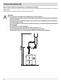
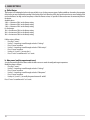
CONNECTION OF THE SMOKE EXHAUST DUCT
When making the hole for the passage of the smoke discharge pipe, it is necessary to take into account the possible presence of flammable
materials. If the hole has to be in a wall made of wood or other thermolabile material, THE INSTALLER MUST first set up the relative wall
fitting (diameter 13 cm minimum) and insulate the pipe of the product passes with appropriate insulating material (1.3 - 5 cm thick with
minimum heat conductivity of 0.07 W/m°K).
The same minimum distance must be applied if the pipe of the product must pass through vertical or horizontal sections near the
thermolabile wall.
It is recommended to use an insulated double-wall pipe in external sections in order to prevent condensation from forming.
The combustion chamber works in negative pressure.
SMOKE OUTLET
Technical Dept. - All rights reserved - Reproduction is prohibited
9
2-INSTALLATION INSTRUCTIONS
Always use pipes and fittings with appropriate seals that guarantee tightness.
It must be possible to inspect all sections of the flue duct and they must be removable for periodic internal cleaning (T-fitting with
inspection hole).
Position the product considering all the above requirements and instructions.
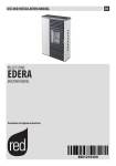
H > 1,7 m
IMPORTANT!
The connection between the appliance and chimney must meet these conditions:
• the smoke duct must be at least category T200 (or higher if required by the smoke temperature of the appliance)
and P1-type (airtight).
• All bends at 90° (max. 3) of the fume outlet duct must, if possible, use T-shaped fittings with inspection points.
(See pellet product accessories).
• It is strictly forbidden to fit a mesh at the end of the exhaust pipe as it could cause the product to malfunction
(due to clogging).
• It is forbidden to use counter-sloping pipes.
• The horizontal section of the smoke duct must not be longer than 2-3 m.
• It is also recommended not to exceed 6 metres in length with the pipe Ø 100 mm.
• The smoke duct must not cross rooms in which it is forbidden to install combustion appliances.
EXAMPLE OF PELLET STOVE INSTALLATION
10
2-INSTALLATION INSTRUCTIONS
CONNECTION TO THE CHIMNEY
The chimney is the fundamental element for smoke expulsion and must therefore comply with the following requirements:
• be waterproof and thermally insulated.
• Be made of suitable materials that resist mechanical stress over time, heat, the effects of the combustion products and any possible
condensation.
• Have a vertical set-up with deviations from the axis of no more than 45° and free of bottlenecks.
• Must be suitable for the specific operating conditions of the product and have the CE marking (EN1856-1, EN1443).
• Must be adequately sized for the draught/smoke expulsion requirements that are necessary for the product to operate correctly
(EN13384-1).
• The internal section is preferably circular.
• In the case of a pre-existing product that has been used, it must be cleaned.
• The chimney must not be shared with other appliances.
The chimney is fundamental for correct operation and safety of your product.
Below are certain rules on correct installation. Any alternative configurations must be suitably sized in accordance with the general
method of calculation of UNI EN 13384-1.
Technical Dept. - All rights reserved - Reproduction is prohibited
11
2-INSTALLATION INSTRUCTIONS
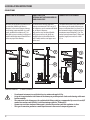
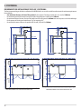
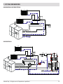
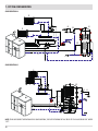
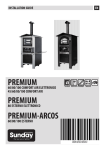
CONNECTIONS
CONNECTION TO THE CHIMNEY
CONNECTION TO AN
EXTERNAL DUCT WITH INSULATED OR
DOUBLE-WALL PIPE
CONNECTION TO THE CHIMNEY
The inside of the chimney should measure
no more than 20x20 cm or 20 cm in
diameter; in the case of a larger chimney,
or a chimney in poor condition (e.g. with
cracks, insufficient insulation, etc.), it is
advisable to insert a stainless steel pipe of
suitable width that extends from the base
to the very top of the chimney.
The inside of the external duct must
measure a minimum of 15x15 cm, or 15
cm in diameter, and a maximum of 20x20
cm, or 20 cm in diameter.
Only stainless steel insulated (doublewall) pipes must be used, which are
smooth on the inside and fixed to the
wall. Flexible stainless steel pipes must
not be used.
The connection between the product and
the chimney or the smoke duct must not
have an inclination that is less than 3% in
the horizontal sections, which must have
a maximum overall length of 2/3 m. The
vertical section between one T-fitting and
another (angle) must not be less than
1.5 m.
mt.0,5 mt.0,5 mt.
1
1
1 0,5 mt.0,5 mt.0,5 mt.
1
1
1
0,5 mt.0,5 mt.0,5 mt.
1
2 - 3 mt.
2 -MAX
3 mt.
2 - MAX
3 mt. MAX
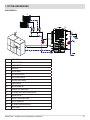
1) WINDPROOF CHIMNEYPOT
•
•
•
•
•
12
3
2
3
2
3
2
3
2
2
3
3
3-5 % 3-5 % 3-5 %
H > 1,5 mt.
3
2
H > 1,5 mt.
3
2
H > 1,5 mt.
2
1
2) CHIMNEY 3) INSPECTION
Use adequate instruments to verify that there is a minimum draught of 5 Pa.
Set-up an inspection hole at the bottom of the chimney to perform periodic checks and cleaning, which must
be done annually.
The connection to the chimney must be sealed and the fittings and pipes recommended by us must be used (CE
marked in accordance with EN1856-2 with the minimum requisites: T200 and P1).
You must ensure that a windproof chimneypot is installed in accordance with the regulations in force.
This type of connection guarantees smoke expulsion even in the event of a temporary power cut.
1
3
2-INSTALLATION INSTRUCTIONS
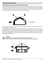
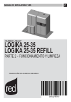
OPERATING PROBLEMS RELATED TO DRAUGHT DEFECTS IN THE CHIMNEY
Of all the weather and geographical conditions which affect the operation of a flue pipe (rain, fog, snow, altitude a.s.l., exposure to
sunlight, direction of facing), the wind is unquestionably the most decisive. In fact, along with thermal depression caused by the difference
in temperature inside and outside of the chimney, there is another type of depression or over-pressure: dynamic pressure caused by the
wind. An updraft always increases depression and therefore the draught. A horizontal wind increases depression provided the chimneypot
has been installed properly. A downdraft always decreases depression, at times inverting it.
A
B
A=LESS FAVOURABLE POINTS
B=MOST FAVOURABLE POINT
Besides the direction and force of the wind, the position of the chimney and the chimneypot with respect to the roof of the building and
the surrounding landscape is also important.
The wind also influences the operation of the chimney indirectly by creating high-pressure and low-pressure zones, not only outside the
building but inside as well. An internal overpressure can be created in rooms that are directly exposed to the wind (2), which can enhance
the draught in the boiler, however, it can be counteracted by the external overpressure if the chimneypot is situated on the side exposed to
the wind (1). On the other hand, a dynamic depression can be created in rooms that are opposite the wind direction (3), which competes
with the natural thermal depression generated by the chimney, however, this can be compensated for (sometimes) by placing the smoke
duct opposite the wind direction (4).
IMPORTANT!
The operation of the product is significantly affected by the flue layout and position.
Hazardous conditions can only be resolved by qualified personnel setting the product appropriately.
WIND
1
4
2
Technical Dept. - All rights reserved - Reproduction is prohibited
3
13
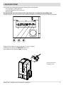
3-DRAWINGS AND TECHNICAL CHARACTERISTICS
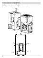
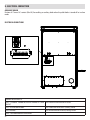
DRAWINGS AND CHARACTERISTICS
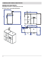
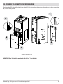
DIMENSIONS OF LOGIKA 25-35 HYDRO (dimensions in mm)
N.B. The 90° bend is not provided with the boiler.
1540
1385
MIN.1700
1200
14
1060
650
30
0
10
100
1950
815
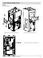
3-DRAWINGS AND TECHNICAL CHARACTERISTICS
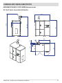
DIMENSIONS OF LOGIKA 25-35 REFILL HYDRO (dimensions in mm)
N.B. The 90° bend is not provided with the boiler.
1235
1385
MIN.1700
1950
815
Technical Dept. - All rights reserved - Reproduction is prohibited
1100
650
30
0
10
100
900
15
3-DRAWINGS AND TECHNICAL CHARACTERISTICS
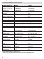
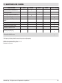
TECHNICAL CHARACTERISTICS
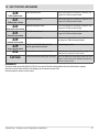
LOGIKA 25
LOGIKA 35
Product class (EN 303-5/2012)
5
5
Rated thermal capacity of the firebox
25.8 kW (22188 kcal/h)
33.8 kW (29068 kcal/h)
Nominal output power:
24.8 kW (20726 kcal/h)
32.1 kW (27606 kcal/h)
Minimum output power
8.3 kW (7138 kcal/h)
8.3 kW (7138 kcal/h)
Efficiency at Max
96.1%
95.0%
Efficiency at Min
91.2%
91.2%
Temperature of exhaust smoke at Max
100°C
120°C
Temperature of exhaust smoke at Min
60°C
60°C
Max configurable temperature
80°C
80°C
Max operating temperature
95°C
95°C
Particles/OGC/Nox (10%O2)
39 mg/Nm3 - 1.1 mg/Nm3 - 163.4 mg/Nm3
33.1 mg/Nm3 - 0.3 mg/Nm3 - 179.5 mg/Nm3
CO at 10% O2 at Min and at Max
0.024 - 0.009%
0.024 - 0.006%
CO2 at Min and at Max
5.89 - 10.2%
5.8 - 10.38%
Recommended draught at Max power
0.10 mbar - 10 Pa
0.10 mbar - 10 Pa
Recommended draught at Min power
0.05 mbar - 5 Pa
0.05 mbar - 5 Pa
Smoke mass
16.4 g/sec
21.0 g/sec
Tank capacity
210 litres (manual feed tank)
210 litres (manual feed tank)
Type of pellet fuel
Pellet diameter 6-8 mm and size 5/30 mm
Pellet diameter 6-8 mm and size 5/30 mm
Pellet hourly consumption
Min ~ 1.5 kg/h* - Max ~ 5.3 kg/h*
Min ~ 1.5 kg/h* - Max ~ 7 kg/h*
Autonomy
At min ~ 100 h* - At max ~ 29 h*
At min ~ 100 h* - At max ~ 22 h*
Heatable volume m
518/40 - 592/35 - 691/30**
690/40 - 789/35 - 920/30**
Water content
90 litres
90 litres
Max operating temperature
3 bar - 300 kPa
3 bar - 300 kPa
Combustion air inlet
0 80 mm
0 80 mm
Smoke outlet
0 100 mm
0 100 mm
Air outlet
100 cm
100 cm2
Rated electrical power (EN 60335-1)
180 W (Max 960 W)
180 W (Max 960 W)
Supply voltage and frequency
230 Volt / 50 Hz
230 Volt / 50 Hz
Net weight
705 kg (with tank)
705 kg (with tank)
Weight with packaging
725 kg
725 kg
3
2
* Data that may vary depending on the type of pellets used.
** Volume that can be heated, according to the power requirement in m3 (respectively 40-35-30 Kcal/h per m3)
16
3-DRAWINGS AND TECHNICAL CHARACTERISTICS
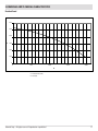
Residual head
600
500
A
400
300
200
100
0
0
500
1000
1500
2000
B
A = Residual Head (mbar)
B = Load (l/h)
Technical Dept. - All rights reserved - Reproduction is prohibited
17
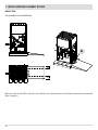
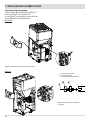
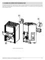
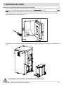
4 - UNPACKING
PREPARATION AND UNPACKING
The LOGIKA boiler is delivered inclusive of all if electrical and mechanical components and already tested at the factory:
Install the boiler in the area set aside for it, making sure it conforms to the requirements. The body of the boiler must only ever be carried
upright with a trolley. The product must always be moved with care. If possible, unwrap the boiler near the chosen place of installation.
The packaging materials are neither toxic nor harmful, and therefore no particular disposal measures are required.
After removing all the packaging, check that the boiler is complete and not damaged. If in doubt, contact the retailer.
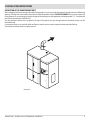
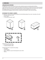
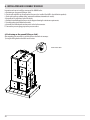
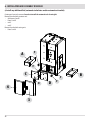
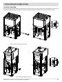
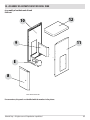
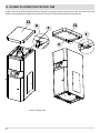
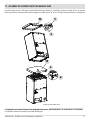
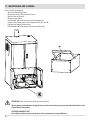
PACKAGING OF THE LOGIKA 25/35 BOILER
The Logika boiler is delivered in three different packages (and with additional packages for accessories), depending on the model:
• A - structure of the boiler (1 pack)
• B - tank (1 pack)
• C - casing of the boiler/tank (1 pack)
A
D
B
E
Easyclean kit accessories (on request)
• D - automatic ash outlet (1 pack)
• E - automatic turbolator (1 pack)
The following documents are provided in the package:
• Plant booklet
• Instruction booklet
• Annex G - Technical test report for thermal plant of less than 35 kW.
• Warranty
18
C
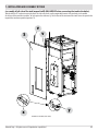
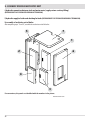
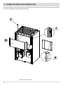
4 - UNPACKING
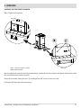
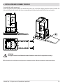
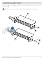
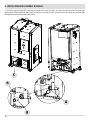
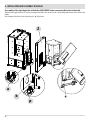
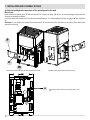
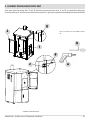
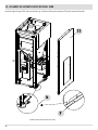
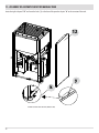
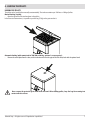
UNPACKING THE STRUCTURE OF THE BOILER
TOOLS: 10 mm face or box spanner
FRONT VIEW
k
FIGURE 1 - STRUCTURE OF LOGIKA 25-35 BOILER
REMOVAL SCREWS OF PACKAGE
j
REAR VIEW
Open the package and remove the two front and back brackets, removing the two screws between each bracket and the boiler and the
two screws that fasten the bracket to the pallet.
Remove the rear bracket, undoing the screws "j" and taking off panel "k" to access the area more easily.
Put the panel "k" back in place when you have done.
Technical Dept. - All rights reserved - Reproduction is prohibited
19
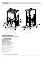
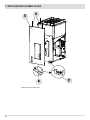
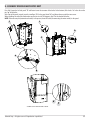
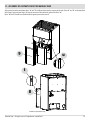
4 - UNPACKING
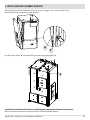
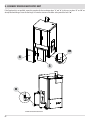
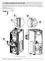
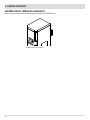
UNPACKING THE TANK
Open the package and remove the two screws between the bracket and the boiler and the two screws that fasten the bracket to the pallet.
FIGURE 2 - LOGIKA 25-35 BOILER MANUAL TANK
REMOVAL SCREWS OF PACKAGE
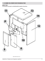
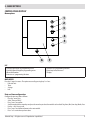
UNPACKING THE COMPLETE CASING
The package of the casing contains the following material:
• BOILER AESTHETICS UNIT
COMPLETE RIGHT-HAND DOOR (1)
COMPLETE RH PANEL (6)
COMPLETE LEFT-HAND DOOR (2)
COMPLETE LEFT-HAND PANEL (5)
COMPLETE BOTTOM RIGHT-HAND DOOR (3)
COMPLETE LEFT-HAND DOOR (4)
COMPLETE TOP DOOR (COVER) (7)
• MANUAL TANK AESTHETICS UNIT
COMPLETE RIGHT-HAND PANEL (12)
COMPLETE LEFT-HAND PANEL (11)
COMPLETE LEFT-HAND DOOR (9)
COMPLETE RIGHT-HAND DOOR (8)
BOTTOM REAR PROTECTION (14)
FRONT PANEL (10)
•
20
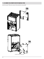
MANUAL LEVER FOR CLEANING TURBOLATORS
FIGURE 2 - LOGIKA 25-35 BOILER REFILL TANK
REMOVAL SCREWS OF PACKAGE
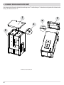
4 - UNPACKING
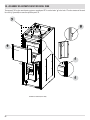
EASYCLEAN KIT PACKAGE
AUTOMATIC TURBOLATOR KIT
ACTUATOR
FEEDER
PLASTIC CAP
AUTOMATIC ASH OUTLET KIT
• EASYCLEAN ASH OUTLET KIT
ASH DOOR SUPPORT 2 X PIECES (see piece "a" page 34)
MICROSWITCH SUPPORT BRACKET 1 X PIECE (see piece page 35)
CENTRAL DOOR SUPPORT 1 X PIECE (see piece "b" page 34)
LOCK CONNECTION 2 X PIECES (see piece “y”page 34)
AUGER ASSEMBLY KIT 2 X PIECES (see page 27)
ASH TRAY ASSEMBLY 2 X PIECES (see piece "c" page 34)
TROLLEY DRAWER ASSEMBLY 1 X PIECE (see page 63)
•
BOLTS AND SCREWS KIT
Technical Dept. - All rights reserved - Reproduction is prohibited
21
5 - POSITIONING
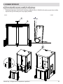
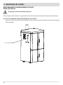
REQUIREMENTS FOR INSTALLATION OF THE PLANT - POSITIONING
MINIMUM REQUIREMENTS FOR LOGIKA BOILER AND MANUAL TANK
22
1000
300
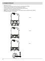
MINIMUM REQUIREMENTS FOR LOGIKA BOILER AND REFILL TANK
MIN.1700
MIN. 300
1950
1385
652
~400
MIN.1700
MIN. 300
MIN.300
1063
1385
~400
652
1000
300
815
1105
MIN.300
1950
815
MIN.600
MIN.600
The most important thing to do before installation of the LOGIKA boiler is to set aside a suitable area that meets the minimum requirements
for installation.
• the minimum clearance in front of the product for the purpose of cleaning, maintenance, etc. must be 1000 mm;
• the minimum permissible distance between the back of the product and a wall must be 400 mm;
• the minimum distance between the top of the product and the ceiling must be 600 mm to ensure easy access to the heat exchanger
for the purpose of cleaning and maintenance (e.g. for removing ash);
• the minimum clearance between the product and the wall (side) must be 300 mm.
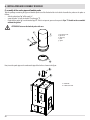
5 - POSITIONING
FOOT ADJUSTMENT
Adjustable feet are mounted at the point of the wheels on the base of the boiler and tank.
It is possible to unscrew the foot with a spanner to stabilise the structure.
1. TURN THE FEET CLOCKWISE TO LOWER THE PRODUCT.
2. TURN THE FEET ANTI-CLOCKWISE TO RAISE THE PRODUCT.
Technical Dept. - All rights reserved - Reproduction is prohibited
FOOT
23
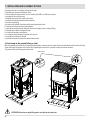
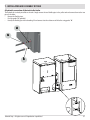
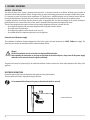
6 - INSTALLATION AND ASSEMBLY OF BOILER
Instructions on how to install the structure of the LOGIKA boiler:
a. Positioning on the ground (lifting or slide).
b. Put the tank and boiler in the room where they are to be installed (but NOT in their definitive position).
c. Check and install any additional kits (automatic turbolators/automatic ash outlet).
d. Assembly of the right-hand side of the boiler.
e. Definitive installation with reference to the diagram showing the minimum requirements.
f. Assemble probe pipe 0 100 at boiler outlet.
g. Assemble the lambda probe and connect it to the boiler connector.
h. Connect the pressure gauge pipe to the pressure outlet.
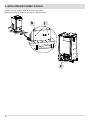
a) Positioning on the ground (lifting or slide).
After unpacking the structure it is possible to move the boiler in two ways:
1) using the lifting hook on the boiler and a hoister.
WEIGHT ABOUT 500 KG
24
6 - INSTALLATION AND ASSEMBLY OF BOILER
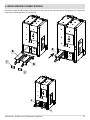
2) using the slide (sold as an accessory).
Put the slide against the pallet and fasten it on with the two screws at pos. x in the figure, aligning it with the wheels of the boiler. The
slide can be fastened onto the pallet with the screws removed from the brackets that previously held the boiler on the pallet.
=
=
x
ATTENTION!
The support surface of the slide must be made of cement or at least be of an equivalent consistency.
b) Put the boiler in the installation area and position it in accordance with the definitive measurements recommended above
Technical Dept. - All rights reserved - Reproduction is prohibited
25
6 - INSTALLATION AND ASSEMBLY OF BOILER
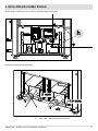
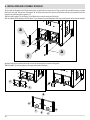
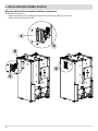
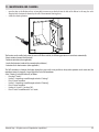
c) Install any additional kits (automatic turbolators and/or automatic ash outlet).
Certain parts have to be removed in order to install the automatic ash cleaning kit.
Remove from the boiler structure unit:
• Ash drawer A and B
• Doors C and D
• unit F
• unit E
Remove from the boiler casing unit:
• Doors 3 and 4.
F
A
F
C
F
E
4
3
26
D
F
B
6 - INSTALLATION AND ASSEMBLY OF BOILER
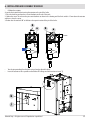
Remove both the augers (K) from the package containing the automatic ash cleaning kit. At this point, remove screw "h" (spanner 10)
and remove carrier "g".
Attention!!
The auger is now no longer secured. To move it, hold it at the front with one hand to avoid dropping it.
K
h
g
K
h
g
Technical Dept. - All rights reserved - Reproduction is prohibited
27
6 - INSTALLATION AND ASSEMBLY OF BOILER
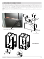
Undo the screws "j" to remove panel "k" at the back of the boiler.
Remove the two caps "z" (using a 25 mm spanner or adjustable pliers).
k
j
z
28
6 - INSTALLATION AND ASSEMBLY OF BOILER
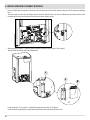
Insert both the auger units (K), making sure the shaft of the auger does not slide at the front. Remove the two gaskets "j" and put them
in again after assembling the doors "c" (see page 34).
K
K
j
K
j
K
K
Technical Dept. - All rights reserved - Reproduction is prohibited
29
6 - INSTALLATION AND ASSEMBLY OF BOILER
It is necessary to put the auger all the way into the structure of the boiler (see figure 1) in order to prevent the shaft of the auger from
coming out of the hole at the back. Next, secure the shaft by re-inserting the carrier "g" and the screw "h" which were removed before
the auger was inserted in the structure of the boiler.
C
h
A
g
30
6 - INSTALLATION AND ASSEMBLY OF BOILER
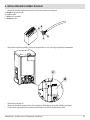
Turn the auger by hand to move the screw "h" to a 90 degree angle to the vertical.
90°
h
Repeat this operation with the other auger.
3 mm
~10 mm
ok
FIG. 1 - APPROX. 10 MM – CORRECT POSITIONING OF THE FEED SCREW
Technical Dept. - All rights reserved - Reproduction is prohibited
31
6 - INSTALLATION AND ASSEMBLY OF BOILER
Take the geared motors "m" out of the package of the trolley drawer.
Make sure that the screw is securely fastened on the ground side (see detail "u") of the shaft of the geared motor, to
prevent it from turning on empty.
t
m
m
Connect an electrical cable with 6.3x0.8 female faston terminals and faston covers to the geared motor. Connect the other end of the
cable with Suko plug to the mains socket. The flat side of the shaft of the geared motor should be perpendicular with the screw "h" (pos.
2) of the carrier. Next, after disconnecting the cable from the geared motor, insert the shaft in the protruding part of the auger. Tighten
the screw "h" (spanner 10).
h
u
1
u
2
m
m
32
6 - INSTALLATION AND ASSEMBLY OF BOILER
In the accessories kit there is also a cable for connecting the geared motors "m". It is necessary to insert the terminal in the remote board
"t" and the fastons in the geared motor "m".
Caution!
While the terminal for the remote board "t" has a set position, the two cables that lead to the geared motor can be
connected either left or right.
t
t
m
m
Technical Dept. - All rights reserved - Reproduction is prohibited
33
6 - INSTALLATION AND ASSEMBLY OF BOILER
The two doors and brackets in the Easyclean kit are pre-assembled in the interest of ease. They need to be disassembled, however, to make
them easier to install. Take the two side brackets "a" and fasten them onto the structure of the boiler with the screws provided in the kit
using the top and bottom holes (spanner 17).
Take the central support "b" and fitting "y" and fasten these onto the structure of the boiler.
After assembling all the brackets, take the doors "c", put them on the protruding bolts of the auger and fasten them back on the brackets
a
b
a
y
applying slight pressure towards the boiler in order to counteract the resistance of the gasket.
Take the gaskets "j" and insert them in the auger to the back of the doors.
c
c
b
a
c
34
y
a
c
6 - INSTALLATION AND ASSEMBLY OF BOILER
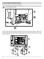
Pull the cable about 30 cm out from the side. Take the micro-switch from the accessory package kit and, before fastening it onto the ash
tray, remove the two screws “v” and low box “s”. Feed the cable from the left side of the boiler through the hole in the box “s” and connect
it to the microswitch. Screw the column "h" onto the right-hand hole of the LH door. Assemble the micro-switch and fasten it on with
washer and nut. It must be parallel with the structure of the boiler.
NOTE: This operation can be done when the left-hand side has already been assembled. If the kit is not available, leave the cable in the
side.
30 cm
v
v
17
CONNECTION TERMINALS FOR MICROSWITCH POS.t
t
S
HOLE FOR CABLE PASSAGE
FASTENING OF MICROSWITCH TO
ASH TRAY
h
Technical Dept. - All rights reserved - Reproduction is prohibited
35
6 - INSTALLATION AND ASSEMBLY OF BOILER
At the back of the boiler, connect the cable from the side to the terminal of the board as shown. The microswitch is now connected.
1 - Remove the bridge.
2 - Insert the cable from side “f”
1
t
t
f
36
2
f
6 - INSTALLATION AND ASSEMBLY OF BOILER
Take the two columns from the trolley package. Insert the seat at the base of the column with the screw of the boiler. At the top, fasten
the column onto the structure with the screw provided.
ATTENTION: This operation can be done when both the sides of the boiler are available.
Technical Dept. - All rights reserved - Reproduction is prohibited
37
6 - INSTALLATION AND ASSEMBLY OF BOILER
When the additional kit for automatic tubulators is also present.
The operations to be done are:
• Remove the protection "z" (detail G) from the left-hand side of the boiler, undoing the 4 screws "x".
• Knock out the pre-perforated panel "A".
X
z
X
X
X
G
A
G
G
38
6 - INSTALLATION AND ASSEMBLY OF BOILER
• Calibrate the actuator.
Set up the limit switch before inserting the actuator on the pin of the boiler
1. Press the clutch key and turn the vise anti-clockwise to the end of the scale.
2. Slacken the screw "a" and turn the piece anti-clockwise as shown in the drawing until the limit switch is 25 mm above the actuator
and then re-close the screw.
3. Slacken also the two bolts "b" to facilitate subsequent insertion of the pin of the boiler.
b
a
b
a
25 mm
•
•
Turn the pin protruding from the boiler using a hand or adjustable pliers.
Insert the actuator as far as possible on the bracket "k" taking care with insertion on insert "j".
k
j
Technical Dept. - All rights reserved - Reproduction is prohibited
39
6 - INSTALLATION AND ASSEMBLY OF BOILER
•
•
•
•
Insert the cable from the actuator in the duct on the left-hand panel of the boiler coating at the point of the actuator installation
hole.
This cable comes out from the rear bottom part of the boiler. Take the three red, white and black wires and connect them to the
terminal with reference to the colours of the other three wires already in place.
Remove modular support "c" from the back of the boiler (lift and slide out) (point 1 in the figure).
Take the feeder and screws out of the turbolator kit.
c
c
d
1
2
•
•
40
Fasten the feeder "d" on support "c" without forcing the screws (point 2 in the figure).
In the electrical wiring locate the sheath containing the four wires with terminals at the ends.
6 - INSTALLATION AND ASSEMBLY OF BOILER
• Remove the terminals and connect the wires to the feeder as shown in the diagram:
A = black wire to connect to VB = red wire to V+
C = blue wire to neutral N
D = brown wire to L
B
A
C
•
D
Reassemble everything in position, putting the support back in its seat (inserting it and pushing it downwards).
c
d
•
•
•
Refasten the protection "z".
Remove the handle for manual cleaning of the turbolators, slackening the screw (with a Phillips screwdriver).
Put the rubber cap, provided in the automatic turbolator kit, in the hole in the place of the handle.
Technical Dept. - All rights reserved - Reproduction is prohibited
41
6 - INSTALLATION AND ASSEMBLY OF BOILER
d) assembly of the right-hand side of the boiler (OBLIGATORY before connecting the boiler to the tank).
Take hold of the right-hand side "Z" and put it up against the boiler. The side to be used is easily recognisable because it has a hole in the
middle.
At the bottom, fit the holes in the side on the pins "p" of the boiler.
Z
a
b
42
p
p
6 - INSTALLATION AND ASSEMBLY OF BOILER
When installing the side of the boiler make sure the pin on side “x” engages in slot “f” at the back of the boiler.
Fasten the panel at the top with the two screws provided.
x
f
Assemble the two rubbers "k" in the pack of bolts and screws on the manual/refill tank.
k
e) definitive installation with reference to the diagram showing the minimum requirements.
Refer to the minimum clearances for the choice of model in the boiler installation diagrams.
Technical Dept. - All rights reserved - Reproduction is prohibited
43
6 - INSTALLATION AND ASSEMBLY OF BOILER
f) assembly of the smoke pipe and lambda probe
Take the packages containing the pipe and lambda probe out of the firebox holder in the boiler. Assemble the probe on the probe as
follows:
• slide the plastic hood "p" off the probe "s".
• screw the probe "s" onto the thread "f" on the pipe "T".
• Check that the gasket “g” is on the intake of pipe “T”. If this is not present, you need to request it. Pipe “T” should not be assembled
without the gasket.
ATTENTION! Fasten on the lambda probe with care.
f
T
s
p
T = Pipe diameter 100
f = pipe thread
p = plastic cap
s = probe
g = gasket
g
Next, insert the probe pipe on the smoke outlet pipe of the boiler as shown in the figure.
A
B
A = PROBE PIPE
B = SMOKE OUTLET PIPE
44
6 - INSTALLATION AND ASSEMBLY OF BOILER
g) assemble the lambda probe and connect it to the boiler connector.
Connect the piston pin of the probe on the connector at the top of the boiler.
h) connect the pressure gauge pipe to the pressure outlet.
Connect the transparent pipe from the top part of the boiler to the pressure connector.
Technical Dept. - All rights reserved - Reproduction is prohibited
45
7 - INSTALLATION AND ASSEMBLY OF TANK
Instructions on how to install the structure of the tank:
a. Positioning on the ground (lifting or slide).
b. Put the tank in the room where it is to be installed (but NOT in its definitive position).
c. assembly of left side of the tank
d. Hydraulic connection of the tank to the boiler
e. mechanical connection between tank and boiler
f. insertion of spark plug
g. electrical and hydraulic connection of the control panel to the tank
h. electrical connection between tank and boiler
i. hydraulic connection between tank and water mains (supply-return-sanitary-filling)
l. hydraulic feed of boiler and check for leaks
k. assembly of aesthetics unit of boiler
m. assembly of trolley drawer, if easyclean kit is present
n. assembly of aesthetic unit of tank
o. hydraulic connection between the tank and water mains
a) Positioning on the ground (lifting or slide).
Open the package and remove the two front and back brackets, removing the two screws between each bracket and the tank and the two
screws that fasten the bracket to the pallet. After unpacking the structure it is possible to move the tank in two ways:
1) by means of the two lifting points on the tank.
WEIGHT 150 KG
ATTENTION! Do not use a single lifting point: use both at the same time.
46
7 - INSTALLATION AND ASSEMBLY OF TANK
2) using the slide (sold as an accessory).
Put the slide against the pallet and fasten it on with the two screws at pos. x in the figure, aligning it with the wheels of the tank. The slide
can be fastened onto the pallet with the screws removed from the brackets that previously held the tank on the pallet.
REFILL TANK
=
=
x
ATTENTION!
The support surface of the slide must be made of cement or at least be of an equivalent consistency.
Technical Dept. - All rights reserved - Reproduction is prohibited
47
7 - INSTALLATION AND ASSEMBLY OF TANK
MANUAL TANK
Same procedure as for the Refill tank.
=
=
x
b) Put the choice of tank (Refill or manual) in the installation area and with reference to the definitive measurements recommended
above (see page 22)
48
7 - INSTALLATION AND ASSEMBLY OF TANK
c) assembly of left side of the tank (manual/refill) (OBLIGATORY before connecting the tank to the boiler).
Take the left side "S" and put it next to the tank. The side to be used is easily recognisable because it has two holes in the middle.
At the base of the panel are two holes "x" to be put on the references "y" at the base of the structure of the tank. Fasten the panel at the
top with the two screws provided, position "v".
v
S
v
y
x
ASSEMBLY OF SIDE PANEL (REFILL TANK)
Technical Dept. - All rights reserved - Reproduction is prohibited
49
7 - INSTALLATION AND ASSEMBLY OF TANK
S
v
x
ASSEMBLY OF SIDE PANEL (MANUAL TANK)
50
y
7 - INSTALLATION AND ASSEMBLY OF TANK
d) hydraulic connection of the tank to the boiler
The hydraulic kit is already installed on the tank. Simply remove the two flexible pipes in the pellet tank and connect them to the two
pipes in the boiler.
• Remove the flexible pipes.
• Find the gasket "k" (provided).
• Identify the flexible pipe with red marking "u" and connect it to the relative one of the boiler using gasket "k".
u
u
k
Technical Dept. - All rights reserved - Reproduction is prohibited
51
7 - INSTALLATION AND ASSEMBLY OF TANK
e) mechanical connection between tank and boiler
Put the tank and boiler in their definitive position.
Next, connect the tank to the boiler with the four screws "x" already mounted on the boiler.
x
x
52
x
x
7 - INSTALLATION AND ASSEMBLY OF TANK
f) insertion of spark plug
Locate the spark plug loosely fitted in the tank and insert it fully, and fasten it in place with the two screws provided, as shown in the
figure. Apply gentle pressure to counteract the resistance of the spring and push the flange all the way down onto the structure.
DETAIL OF FASTENING OF SPARK PLUG (MANUAL TANK)
DETAIL OF FASTENING OF SPARK PLUG (REFILL TANK)
Technical Dept. - All rights reserved - Reproduction is prohibited
53
7 - INSTALLATION AND ASSEMBLY OF TANK
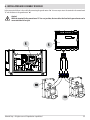
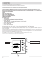
g) electrical and hydraulic connection of the control panel to the tank
Manual tank
Locate the main instrument panel "P" with control panel "n" and pressure gauge "m" which is in the tank package, and proceed with
electrical and hydraulic installation.
Connect the cable of the control panel "n" to the printed circuit board pos. "o" and the capillary of the pressure gauge "m" to the hydraulic
kit.
Attention! It is not possible to assemble the instrument panel "P" until the sides of the tank have been assembled. Put it down on the
ground for time being.
P
n
m
CENTRAL PANEL WITH CONTROL PANEL AND PRESSURE GAUGE (manual tank)
ELECTRICAL CONNECTION OF CONTROL PANEL (manual tank)
o
54
POSITION FOR ELECTRICAL CONNECTION OF CONTROL PANEL (manual
tank)
7 - INSTALLATION AND ASSEMBLY OF TANK
Refill tank
Connection of control panel.
p
n
m
CENTRAL PANEL WITH CONTROL PANEL AND PRESSURE GAUGE (refill
tank)
ELECTRICAL CONNECTION OF CONTROL PANEL (refill tank)
o
Technical Dept. - All rights reserved - Reproduction is prohibited
POSITION FOR ELECTRICAL CONNECTION OF CONTROL PANEL (refill tank)
55
7 - INSTALLATION AND ASSEMBLY OF TANK
Connection of pressure gauge.
a) Remove fitting "R" from the tip of the capillary "C".
b) Unscrew fitting "T" on the hydraulic unit.
c) Insert fitting "T" on the capillary by means of the slot.
d) Screw fitting "T" onto the hydraulic unit.
Manual tank
CONNECTION OF PRESSURE GAUGE TO HYDRAULIC KIT (manual tank)
Refill tank
C = PRESSURE GAUGE CAPILLARY
R = FITTING ON CAPILLARY
T = FITTING MOUNTED ON HYDRAULIC UNIT
C
R
T
CONNECTION OF PRESSURE GAUGE TO HYDRAULIC
KIT (refill tank)
56
7 - INSTALLATION AND ASSEMBLY OF TANK
h) electrical connection between tank and boiler
Connect the two piston pins of the tank to the piston pins of the boiler. The connection of the piston pin on the boiler is recognisably
different (see image below). It is necessary to put the piston pin in the socket and to turn the locking ring clockwise until it is stops.
The connections are not the same and cannot, therefore, be inverted. Do not apply unnecessary force.
PIN CABLES FROM TANK TO BE CONNECTED TO
BOILER
PISTON PIN
Technical Dept. - All rights reserved - Reproduction is prohibited
PISTON PIN CONNECTOR AT BACK OF BOILER
57
8 - ASSEMBLY OF BOILER AESTHETICS UNIT
i) hydraulic connection between tank and water mains (supply-return-sanitary-filling)
(RESPONSIBILITY OF SPECIALISED HYDRAULIC TECHNICIAN)
l) hydraulic supply to boiler and checking for leaks (RESPONSIBILITY OF SPECIALISED HYDRAULIC TECHNICIAN).
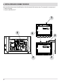
k) assembly of aesthetics unit of boiler
After completing steps "i" and "l", assemble the aesthetics unit of the boiler.
5
7
1
2
6
4
3
For convenience, the panels are identified with the numbers in the picture.
BOILER AESTHETICS UNIT
58
8 - ASSEMBLY OF BOILER AESTHETICS UNIT
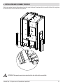
First of all, locate the left side panel "5" and fasten it onto the structure of the boiler. At the bottom, fit the holes "o" in the side on the
pins ''p'' of the boiler.
At the top of the panel, instead, insert the two flaps ("h") in the gaps (detail "t") and fasten them on with the two screws.
When installing the side of the boiler make sure the pin on side “x” engages in slot “f” at the back of the boiler.
NOTE: If the accessory kit (automatic ash outlet) is not present, leave the cable (for connecting the micro-switch) in the panel.
t
5
h
5
o
p
x
f
ASSEMBLY OF LEFT-HAND SIDE PANEL OF BOILER
Technical Dept. - All rights reserved - Reproduction is prohibited
59
8 - ASSEMBLY OF BOILER AESTHETICS UNIT
After fastening the left panel on the boiler, locate the top cover "7" and feed the pins "s" above the two side panels of the boiler into the
fittings "v" at the base of cover "7".
7
v
s
5
ASSEMBLY OF TOP COVER OF BOILER
60
7
8 - ASSEMBLY OF BOILER AESTHETICS UNIT
At this point, locate the two top doors "1" and "2" and fasten them onto the boiler. Doors "1" and "2" are already fitted with hinges.
Fasten the two hinges "z" onto the structure of the boiler using the holes "g" and screws provided in the package of the manual/refill tank.
g
2
Tools: Screwer with cross insert "a" or Phillips screwdriver
"b".
b
1
g
z
a
ASSEMBLY OF TOP DOORS OF BOILER
Technical Dept. - All rights reserved - Reproduction is prohibited
61
8 - ASSEMBLY OF BOILER AESTHETICS UNIT
If the Easyclean kit is not available, repeat this procedure for the two bottom doors "3" and "4". In this case, too, doors "3" and "4" are
already fitted with hinges. Fasten the two hinges "n" onto the structure of the boiler at the point of the holes "m".
m
4
3
n
ASSEMBLY OF BOTTOM DOOR OF BOILER
62
9 - ASSEMBLY OF TROLLEY
m) if the easyclean kit is present, assemble the trolley drawer.
Complete the assembly of the automatic ash outlet kit by inserting the trolley.
• To facilitate the operation, at least for the first few times, remove the door "z" (FIGURE A) of the trolley to permit better visibility.
• Adjust the foot "p" of the trolley to tilt it very slightly (FIGURE B).
FIGURE A
FIGURE B
A
i
z
p
Technical Dept. - All rights reserved - Reproduction is prohibited
63
9 - ASSEMBLY OF TROLLEY
•
•
•
•
•
•
•
Open doors "1" and "2".
Hold the trolley with both hands and move it up to the structure of the boiler (FIGURE 1).
Engage the intakes of the trolley in the two protruding augers (FIGURE 2).
Use one hand to lift handle "i" and another to push the trolley towards the boiler.
Lower handle "i" to secure the trolley onto the structure.
CHECK: The auger intake should protrude about 13 mm further out than the intake of the trolley (FIGURE 3).
Re-assemble the top door "z" of the trolley.
FIGURE 1
FIGURE 2
~13 mm
FIGURE 3
64
10 - ASSEMBLY OF AESTHETICS UNIT OF REFILL TANK
n) assembly of aesthetic unit of tank
Refill tank
12
10
9
11
E
8
REFILL TANK AESTHETICS UNIT
For convenience, the panels are identified with the numbers in the picture.
Technical Dept. - All rights reserved - Reproduction is prohibited
65
10 - ASSEMBLY OF AESTHETICS UNIT OF REFILL TANK
Locate the right side panel "11" and insert the holes "y" at the base of the panel on the pins "k" on the structure of the tank.
11
k
y
ASSEMBLY OF RIGHT-HAND SIDE PANEL (REFILL TANK)
66
10 - ASSEMBLY OF AESTHETICS UNIT OF REFILL TANK
The central instrument panel "E" with control panel and pressure gauge has already been connected to the hydraulic kit and printed circuit
board (see dedicated pages). Once the right panel has been mounted, it can be assembled on the structure of the tank by engaging parts
"g" in holes "f".
HOW TO INSERT INSTRUMENT PANEL "E":
A
B
A = INSERT
B = PUSH DOWN
f
g
f
g
E
ASSEMBLY OF CENTRAL PANEL (REFILL TANK)
Technical Dept. - All rights reserved - Reproduction is prohibited
67
10 - ASSEMBLY OF AESTHETICS UNIT OF REFILL TANK
The top panel "9" has the same fastening system as central panel "E". Insert the hooks "g" in the holes "f" on the structure of the tank.
Use screw "y" (provided) to secure the top of the panel "9".
y
g
9
f
f
ASSEMBLY OF TOP PANEL (REFILL TANK)
68
10 - ASSEMBLY OF AESTHETICS UNIT OF REFILL TANK
The bottom door "A" is already fitted with hinges (detail "t") to be fastened onto the structure of the tank using the holes present (detail
"u") and the screws provided.
t
u
8
8
s
ASSEMBLY OF DOOR (REFILL TANK)
IMPORTANT: Door "8" should be positioned with the lock "s" to the right.
Technical Dept. - All rights reserved - Reproduction is prohibited
69
10 - ASSEMBLY OF AESTHETICS UNIT OF REFILL TANK
In order to fasten cover “12” already fitted with hinges (detail “t”) it is necessary to fasten it first to the holes “u” in the structure of the tank
(with the screws provided) then engage the ring on piston “x” on pin “z”. Repeat this procedure for the second piston.
12
u
12
z
t
x
ASSEMBLY OF DOOR (REFILL TANK)
70
11 - ASSEMBLY OF AESTHETICS UNIT OF MANUAL TANK
MANUAL TANK
For convenience, the panels are identified with the numbers in the picture.
11
13
14
p
12
10
8
9
MANUAL TANK AESTHETICS UNIT
Technical Dept. - All rights reserved - Reproduction is prohibited
71
11 - ASSEMBLY OF AESTHETICS UNIT OF MANUAL TANK
Locate the right side panel ''12'' and insert the holes ''y'' at the base of the panel on the pins ''k'' on the structure of the tank.
12
y
k
ASSEMBLY OF RIGHT-HAND SIDE PANEL (MANUAL TANK)
72
11 - ASSEMBLY OF AESTHETICS UNIT OF MANUAL TANK
The central instrument panel ''p'' with control panel and pressure gauge has already been connected to the hydraulic kit and printed
circuit board (see dedicated pages). After assembling also the right panel with holes "s" it is possible to install it on the structure of the
tank by engaging the parts "t".
s
t
p
ASSEMBLY OF CENTRAL PANEL (MANUAL TANK)
Technical Dept. - All rights reserved - Reproduction is prohibited
73
11 - ASSEMBLY OF AESTHETICS UNIT OF MANUAL TANK
The top panel ''10'' has the same fastening system as central panel ''p''. Insert the hooks ''g'' in the holes ''f'' on the structure of the tank.
Use screw ''y'' (provided) to secure the top of the panel ''10''.
y
f
10
g
ASSEMBLY OF TOP PANEL (MANUAL TANK)
74
11 - ASSEMBLY OF AESTHETICS UNIT OF MANUAL TANK
At this point, locate the two bottom doors "8" and "9" and fasten them onto the structure of the tank. Doors ''8'' and ''9'' are already fitted
with hinges. Fasten the two hinges “t” onto the structure of the tank at the point of the holes ''u''.
Doors “8” and “9” should be assembled with the ground part on the outside.
9
u
t
8
ASSEMBLY OF DOOR (MANUAL TANK)
Technical Dept. - All rights reserved - Reproduction is prohibited
75
11 - ASSEMBLY OF AESTHETICS UNIT OF MANUAL TANK
Fasten the rear panel "14" onto the structure of the tank with the screws provided.
14
14
ASSEMBLY OF REAR PANEL (MANUAL TANK)
76
11 - ASSEMBLY OF AESTHETICS UNIT OF MANUAL TANK
In order to fasten the cover ''13'', which is already fitted with hinges (detail ''t''), attach it first to the holes (detail ''u'') on the structure
of the tank (with the screws provided) and then engage the ring of the piston ''x'' on pin ''z''. Repeat the procedure for the second piston.
t
13
x
13
z
u
ASSEMBLY OF COVER (MANUAL TANK)
o) hydraulic connection between the tank and water mains (RESPONSIBILITY OF A SPECIALIST TECHNICIAN)
It is advisable to connect the tank and system with flexible pipes.
Technical Dept. - All rights reserved - Reproduction is prohibited
77
Via La Croce n°8
33074 Vigonovo di Fontanafredda (PN) – ITALY
Telefono: +39 0434/599599 r.a.
Fax: +39 0434/599598
Internet: www.mcz.it
e-mail: [email protected]
8901231800
REV. 0
20/11/2012
INSTALLATION GUIDE
PELLET BOILER
LOGIKA 25-35
LOGIKA 25-35 REFILL
PART 2 - OPERATION AND CLEANING
Translation of the original instructions
GB
TABLE OF CONTENTS
TABLE OF CONTENTS....................................................................................... II
1 - PLUMBING CONNECTION.. ........................................................................... 1
2- FILLING THE SYSTEM.. ................................................................................. 2
3 - GENERAL WARNINGS. . ................................................................................ 4
4 - LOADING THE PELLETS.. .............................................................................. 7
2 - MENU OPTIONS......................................................................................... 9
6 - ADJUSTMENTS MENU................................................................................17
7 - SYSTEM CONFIGURATION...........................................................................18
8 - ELECTRICAL CONNECTION..........................................................................22
9 - START-UP/SHUT-DOWN.............................................................................23
10 - SAFETY DEVICES AND ALARMS..................................................................24
11 - MAINTENANCE AND CLEANING. . ................................................................28
12 - TROUBLESHOOTING.. ...............................................................................34
13 - WIRING DIAGRAM...................................................................................37
II
1 - PLUMBING CONNECTION
PLUMBING CONNECTION
IMPORTANT:
The connections depend on the type of hydraulic kit installed and the type of system configuration.
IMPORTANT!
The boiler must be installed by qualified personnel who can testify to the conformity of the system in accordance
with the applicable laws in force.
The Company will not be held responsible for damage to persons or things in the event of failed or incorrect operation
if the aforementioned warnings are not complied with.
IMPORTANT!!!
CLEAN THE ENTIRE SYSTEM BEFORE CONNECTING THE BOILER, IN ORDER TO REMOVE ALL RESIDUE AND DEPOSITS.
Upstream from the stove, always install shutters so as to disconnect it from the plumbing system should it be
necessary to move it, or when it requires routine and/or special maintenance.
Connect the stove using hoses so that the stove is not too strictly connected to the system, and to allow slight
movements.
CLEANING THE SYSTEM
In order to protect the thermal system against harmful corrosion, scale or deposits, it is essential to clean the system in accordance with
standard UNI-CTI 8065 before installing the appliance, using appropriate products like Sentinel X300 (new systems), X400 and X800 (old
systems) or Fernox Cleaner F3.
Complete instructions are provided with the products but it is possible to contact the manufacturer SENTINEL PERFORMANCE SOLUTIONS
LTD or FERNOX COOKSON ELECTRONICS directly for further information. After cleaning the system, it is recommended to use Sentinel X100
or Fernox Protector F1 inhibitors to protect it against corrosion and deposits.
It is important to check the concentration of the inhibitor after making any changes to the system and during maintenance checks,
following the recommendations of the manufacturers (the retailers can offer tests).
The outlet of the safety valve has to be connected to a collection intake for purging in the event of maintenance.
Attention: Failure to clean the thermal system or to use an adequate inhibitor will invalidate the warranty of the
appliance and of the other accessories like the pump and valves.
Technical Dept. - All rights reserved - Reproduction is prohibited
1
2- FILLING THE SYSTEM
FILLING THE SYSTEM
Fill the system slowly to allow air bubbles to pass through the vent holes of the heating system. For closed circuit heating systems, the
filling pressure of the system at cold and the pre-inflation pressure of the expansion tank must be the same.
• The water used for filling the heating system must be decontaminated and not contain air.
Attention!
Do not mix heating water with incorrect concentrations of anti-freeze or anti-corrosion substances! This could
damage the gaskets and cause noise during operation.
After making all the hydraulic connections, pressure-test the seals by filling the boiler.
Before filling, check the filling pressure of the expansion tank.
This must be done with care by doing the following:
• open the air vent valves of the radiators, boiler and system;
• gradually open the filling tap of the system, making sure that any automatic air vent valves in the system work correctly;
• close the vent valves of the radiators as soon as water comes out;
• check at the pressure gauge of the system that the pressure reaches 1 bar approx.
• close the filling tap of the system and then open the vent valves of the radiators again to purge any air;
• check the seal of all the connections;
• after starting up the boiler for the first time and bringing the system up to temperature, stop the pumps and repeat the air purging
procedure;
• allow the system to cool down and, if necessary, bring water pressure back up to 1 bar;
2
2- FILLING THE SYSTEM
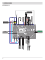
Fill the heating system manually using the tap with check valve in the hydraulic kit.
• Connect or plug the H2O hot outlet "U".
• Connect the H2O cold input "K" to the system.
• Open the tap "R".
This operation does not need to be done if the system already has an automatic or manual filling valve.
During this operation, any air in the system is released from the automatic vent valve located at the top of the body of the boiler.
R
U
K
To allow the valve to purge, unscrew the side cap by 1/2 a turn. (see figure)
The filling pressure of the system WHEN COLD must be 1 bar.
Upon completion of this operation, always close the tap.
PURGE VALVE WITH SIDE CAP
UNSCREWED BY 1 TURN
Technical Dept. - All rights reserved - Reproduction is prohibited
3
3 - GENERAL WARNINGS
GENERAL PRECAUTIONS
The electrical safety of the system is guaranteed only when this is connected correctly to an efficient earthing system installed in
accordance with the safety standards in force: the pipes of the gas, water and heating systems do not constitute a suitable earth system.
It is necessary to ensure this essential safety requirement; if in doubt, have a qualified technician test the electrical system with care
because the manufacturer of the boiler does not assume responsibility for damage caused by the absence of an earthing system.
A qualified technician should check that the electrical system is compatible with the max consumption of the system, checking in
particular that the cross-section of the cables of the system is compatible with the power consumption of the loads.
The use of any component that requires electrical energy requires compliance with certain essential rules like:
• do not touch the appliance with wet and/or damp parts of the body and/or when barefoot;
• do not pull on the electrical cables;
• do not expose the appliance to the elements (rain, sun, etc.);
• do not allow children or inexperienced persons to use the appliance.
Connection to 230V power supply.
The installation of additional electrical components of the boiler requires electrical connection to a230V - 50Hzpower supply: This
connection must be done in accordance with the national standards in force.
Danger!
Electrical installation must be entrusted to a single qualified technician.
Before making the connections or carrying out any work on the electrical parts, always turn off the power supply
and make sure it cannot be turned on again accidentally.
The power cable must be replaced only by an authorised technician. Failure to observe the above could compromise the safety of the
appliance.
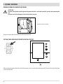
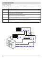
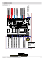
ELECTRICAL CONNECTION
Connect the power cable first to the back of the tank and then to the electrical mains.
The main switch at the back is simply for turning on the boiler.
It is recommended to disconnect the power cable when the boiler is not used.
ELECTRICAL CONNECTION
4
3 - GENERAL WARNINGS
BEFORE START-UP
GENERAL PRECAUTIONS
After a long period of inactivity, use a vacuum cleaner with long tube to remove any traces of pellets in the tank that could
have absorbed humidity and are no longer suitable for combustion.
The first start-up may not be successful as the feed screw is empty and does not always manage to load the required
amount of pellets in the brazier to reach the threshold temperature, despite the presence of fire.
It is good practice to guarantee effective ventilation in the room during the initial start-up, as the boiler will emit
some smoke and smell of paint.
Technical Dept. - All rights reserved - Reproduction is prohibited
5
3 - GENERAL WARNINGS
OPENING/CLOSING THE DOOR OF THE FIREBOX
ATTENTION!
The door of the firebox should be opened only when the boiler is cold and at standstill, and only when removing the
ash.
The door must be closed properly for the boiler to work correctly.
OPENING THE DOOR OF THE FIREBOX
To open the internal door, lift and pull the handle towards yourself.
SETTINGS TO BE CARRIED OUT BEFORE THE INITIAL START-UP
6
After connecting the power cable to the back of the product, turn the switch at the back to position(I). Turn the boiler on or off at button
6 on the control panel.
6
4 - LOADING THE PELLETS
LOADING THE PELLETS
The pellets can be loaded either manually or automatically. The tank can contain up to 210 litres or 140 kg of pellets.
Manual loading (Logika):
• Open the top cover of the tank and pour in the pellets.
In the interest of convenience, it is possible to put the bag (15 kg) on the grate and cut it.
Automatic loading (with remote tank of 100/200 or 400 kg - optional - see accessories):
• Remove the round plate from the door, cut the insulation and insert the pipe of the filler. Next, load with the optional tank.
Never remove the protective grate from inside the tank. When loading pellets, keep the bag from coming into
contact with hot surfaces.
Technical Dept. - All rights reserved - Reproduction is prohibited
7
4 - LOADING THE PELLETS
AUTOMATIC PELLET LOADING OF LOGIKA REFILL
Refer to section 3 of the manual for automatic pellet loading with the BIG-BAG system.
AUTOMATIC LOADING OF LOGIKA REFILL
8
2 - MENU OPTIONS
2 - MENU OPTIONS
CONTROL PANEL DISPLAY
Menu options
1
2
3
4
5
6
7
KEY
1. Scrolling up through the programming menu.
2. Scrolling down through the programming menu
3. Menu/confirmation.
4. Increase set / programming functions
5. Decrease set / programming functions
6. Start/stop boiler/exit menu
7. Display.
MAIN MENU
Press key 3 (menu) to access. The options accessed by pressing keys 1 or 2 are:
• Date and Time
• Timer
• Settings
• Info
Date and time configuration
Configure the time and date as follows:
• Press the "menu" key.
• Select "Date and Time".
• Press "menu" to confirm.
• Scroll through with the arrow keys and press the menu key to select the variables to be edited: Day, Hour, Min, Num. day, Month, Year.
• Use the + and - keys to edit.
• Press "menu" to confirm and move to the next variable.
• Press "esc" to exit when you have done.
Technical Dept. - All rights reserved - Reproduction is prohibited
9
2 - MENU OPTIONS
CONFIGURATION OF PROGRAMMED MODE (TIMER) - Main menu
The current time and date must be configured to ensure correct operation of the timer.
There are six configurable TIMERS; for each one, the user can select a start and stop time and the days of the week when it is in use.
When one or more programs are active, the status of the boiler and the TIMER "n" alternate on the display. "n" is the number of timer
programs in use, separated by dashes.
Example:
TIMER 1 Timer 1 program active.
TIMER 1-4 Timer 1 and 4 programs active.
TIMER 1-2-3-4-5-6 All timer programs active.
EXAMPLE OF PROGRAMMING
With the boiler on or off:
• access the MENU,
• use the arrow keys (1 and 2) to scroll through to the TIMER option,
• Press the "Menu" key
• The system proposes "P1" (Press keys 1 and 2 for timers P2, P3, P4, P5 and P6).
• Press the "Menu" key to activate "P1".
• press + - and select "ON"
• press the "Menu" key to confirm
At this point the start time is 00:00. Press the + - key to set the start time and press the "menu" key to confirm.
Next, the proposed stop time is 10 minutes later than the configured start time: press the + key and edit the stop time, and press the
"menu" key to confirm.
Next, you are asked to set the days of the week when the configured timer is to be enabled or disabled. Use the - or + key to select the day
on which to enable the timer and press the "menu" key to confirm. The selected day is highlighted. If no day is selected for enabling the
timer, the timer program is no longer enabled on the status window.
Next, program the other days or press "ESC" to exit. Repeat this procedure to program the other timers.
Example of Timer window (boiler on from 6:00 to 22:00, Monday to Friday:
1
2
CURRENT TIME
0 1 2 3 4 5 6 7 8 9 1 1 1 1 1 1 1 1 1 1 2 2 2 2
0 1 2 3 4 5 6 7 8 9 0 1 2 3
da 06:00
P1 On a 22:00
Lu Ma Me Gi Ve Sa Do
3
4
5
6
10
THE IGNITION PERIOD IS SHOWN ON THE
DISPLAY DURING ACTIVATION OF THE TIMER
2 - MENU OPTIONS
NOTES ON USE OF THE TIMER
• The start time can be between 00:00 and 23:50
• If the stop time has not yet been saved, the program proposes a start time at +10 minutes.
• If a timer program stops the boiler at 24:00 on one day and another program starts it up at 00:00 on the next day: the boiler remains
ON.
• If a program proposes start-up and/or shut-down at times in another timer program: if the boiler is already on, the start has no effect
while OFF turns off the boiler.
• When the boiler is on and the timer is active, pressing the OFF key turns off the boiler; the boiler then restarts automatically at the
next time of the timer.
• When the boiler is off and the timer is active, pressing the ON key turns on the boiler; the boiler then stops automatically at the next
time of the timer.
EXAMPLES OF PROGRAMMING
P1
on
off
08:00
12:00
P2
day
on
off
day
Monday
11:00
14:00
Monday
Boiler on between 08:00 and 14:00
P1
on
off
08:00
11:00
P2
day
on
off
day
Monday
11:00
14:00
Monday
Boiler on between 08:00 and 14:00
P1
P2
on
off
day
on
off
day
17:00
24:00
Monday
00:00
06:00
Tuesday
Boiler on between 17:00 on Monday to 06:00 on Tuesday
SETTINGS MENU
The SETTINGS menu is for configuring use of the boiler:
a. Language.
b. Cleaning (shown only when boiler is off).
c. Auger loading (shown only when boiler is off).
d. Auto Eco.
e. Eco off T
f. Pump on T
g. Pellet recipe.
h. Max power
i. Component test (shown only when boiler is off).
j. Lambda test (shown only when boiler is off).
k. "Chimney sweeper" function (can be enabled only when boiler is on, for checking emissions in field).
l. System configuration (factory settings: system 02).
m. Season
n. Solar (on/off for configurations 4-6).
o. Technical menu.
NOTE: Some of the options listed above cannot be enabled in certain "system configurations".
Technical Dept. - All rights reserved - Reproduction is prohibited
11
2 - MENU OPTIONS
a - Language
Select the language as follows:
• Press the "menu" key.
• Use the arrow keys to scroll through and select "Settings"
• Press “menu” to confirm.
• Use the arrow keys to scroll through and select "language".
• Press “menu” to confirm.
• Use the + - keys to select the required language (IT/EN/DE/FR/ES/NL/PL/DA)
• Press "menu" to confirm and "esc" to exit.
b - Cleaning
This function can be enabled only when the stove is off. When enabled, the following operations are carried out automatically:
- Brazier rotation (removal of residual ash)
- Turbolator activation (when applicable)
- Smoke Fan Activation (intake of ash removed with turbolators)
- Activation of ash drawer motors (when applicable)
The 180" countdown is shown on the display during these steps and it is not possible to do any other operations at the same time (the
countdown cannot be stopped). A sound signals the end of the countdown.
Select "Cleaning" (only with boiler off) as follows:
• Press key 3 "menu".
• Use the 1-2 arrow keys to scroll through and select ''Settings''
• Press 3 “menu” to confirm.
• Use the 1-2 arrow keys to scroll through and select "Cleaning".
• Press 3 “menu” to confirm.
• Use keys 4 (+) and 5 (-) to select "On".
• Press 3 ''menu'' to confirm and 6 ''esc'' to exit.
Refer to chapter 11 "Cleaning and Maintenance".
c - Load auger
This is for filling the the pellet loading system. This can be enabled only when the boiler is off. A countdown appears. The auger stops
automatically at the end of the countdown and the menu closes.
Select ''Load auger'' (only with boiler off) as follows:
• Press key 3 ''menu''.
• Use the 1-2 arrow keys to scroll through and select ''Settings''
• Press 3 “menu” to confirm.
• Use the 1-2 arrow keys to scroll through and select ''Load auger''.
• Press 3 “menu” to confirm.
• Use keys 4 (+) and 5 (-) to select ''Enable''.
• Press 3 ''menu'' to confirm and 6 ''esc'' to exit.
Note: There is a delay between activation and start-up of the auger during which time the fire damper opens.
12
2 - MENU OPTIONS
d - Auto-Eco
The Auto-Eco function turns the boiler off automatically at the configured time of the "Eco Stop T" parameter when no heat is required by
the devices connected to the boiler: external thermostat (configurations 1-2-3), flow switch (configuration 2), thermostat/puffer probe
(configuration 5-6) or thermostat/boiler probe (configuration 3-4). If all the devices present are satisfied, the "ECO stop T" timer starts to
count down.
When the boiler turns off, ECO - ECO ACTIVE appears on the panel.
The following conditions have to be met simultaneously for the ECO to restart:
• Power recall
• 5 minutes have passed since shut-down.
• TH2O < TSetH2O.
NOTE: In certain system configurations, it can be useful to disable automatic shut-down of the boiler (e.g. in configurations 2 or 3) and
keep the system running at minimum power. In other configurations, this function cannot be disabled.
Disable the Auto-Eco function as follows:
• Press key 3 ''menu''.
• Use the 1-2 arrow keys to scroll through and select ''Settings''
• Press 3 “menu” to confirm.
• Use the 1-2 arrow keys to scroll through and select ''Auto-Eco''.
• Press 3 “menu” to confirm.
• Use keys 4 (+) and 5 (-) to select ''Off''.
• Press 3 ''menu'' to confirm and 6 ''esc'' to exit.
e - Eco stop T (Eco stop time)
The "ECO stop T" can be adjusted to ensure correct operation of the system in which the boiler is installed and to avoid constant stopping
and starting when heat requirements are subject to change suddenly.
Select the Eco stop T function as follows:
• Press key 3 ''menu''.
• Use the 1-2 arrow keys to scroll through and select ''Settings''
• Press 3 “menu” to confirm.
• Use the 1-2 arrow keys to scroll through and select ''Eco stop T''.
• Press 3 “menu” to confirm.
• Use keys 4 (+) and 5 (-) to enter the minutes.
• Press 3 ''menu'' to confirm and 6 ''esc'' to exit.
f - Pump On T (pump temperature) (ONLY FOR EXPERIENCED USERS)
This option enables adjustment of the pump activation temperature.
Select the Pump On T function as follows:
• Press key 3 ''menu''.
• Use the 1-2 arrow keys to scroll through and select ''Settings''
• Press 3 “menu” to confirm.
• Use the 1-2 arrow keys to scroll through and select ''Pump On T''.
• Press 3 “menu” to confirm.
• Use keys 4 (+) and 5 (-) to enter the °C.
• Press 3 ''menu'' to confirm and 6 ''esc'' to exit.
Technical Dept. - All rights reserved - Reproduction is prohibited
13
2 - MENU OPTIONS
g - Pellet Recipe
This function is for adapting the boiler to the type of pellet in use. As there are many types of pellet available on the market, the operation
of the boiler can vary considerably according to the quality of the fuel. When the pellets clog up the brazier due to excess loading of fuel
or when the flames are high even at low power, or when the flames are low, it is possible to decrease/increase the amount of pellets in
the brazier:
Available values:
-30% = A decrease of 30% on the factory setting.
-20% = A decrease of 20% on the factory setting.
-10% = A decrease of 10% on the factory setting.
0 = No changes.
10% = An increase of 10% on the factory setting.
20% = An increase of 20% on the factory setting.
30% = An increase of 30% on the factory setting.
Edit the recipe as follows:
• Press key 3 ''menu''.
• Use the 1-2 arrow keys to scroll through and select ''Settings''
• Press 3 “menu” to confirm.
• Use the 1-2 arrow keys to scroll through and select ''Pellet recipe''.
• Press 3 “menu” to confirm.
• Use keys 4 (+) and 5 (-) to enter the %.
• Press 3 ''menu'' to confirm and 6 ''esc'' to exit.
h - Max power (only for experienced users)
Sets the max power limit of the flames which the boiler can use to reach the configured target temperature.
Modify the power as follows:
• Press key 3 ''menu''.
• Use the 1-2 arrow keys to scroll through and select ''Settings''
• Press 3 “menu” to confirm.
• Use the 1-2 arrow keys to scroll through and select ''Max power''.
• Press 3 “menu” to confirm.
• Use keys 4 (+) and 5 (-) to modify the power between 01 and 05.
Press 3 ''menu'' to confirm and 6 ''esc'' to exit.
14
2 - MENU OPTIONS
i - Component test
This can be done only when the boiler is off and allows you to select the components to be tested:
• Spark plug: runs for a test time during which the panel shows the countdown timer in seconds.
• Auger: this is fed for a test time during which the panel shows the countdown time in seconds.
• Aspirator: this is run at 2500 rpm for a test time during which the panel shows the countdown time in seconds.
• Pump: this is run for a test time during which the panel shows the countdown time in seconds.
• 3 way: the 3-way valve is run for a test time during which the panel shows the countdown time in seconds.
NOTE: The technician can stop the test time whenever by quickly pressing the ON/OFF key.
Enable the "Component test" function (only with boiler off) as follows:
• Press key 3 ''menu''.
• Use the arrow keys to scroll through and select "Settings"
• Press 3 “menu” to confirm.
• Use the arrow keys to scroll through and select ''Component test''
• Press 3 “menu” to confirm.
• Use the + - keys to select the test to be carried out.
Press "menu" to confirm and "esc" to exit
j - Lambda Test (can only be activated when the stove is off)
This function only be activated when the boiler is off. When activated, the fan runs at maximum and the Lambda probe is powered. This
state lasts for 60" and the countdown is shown on the panel.
NOTE: The technician can stop this phase at any moment by quickly pressing the on/off key.
The percentage of oxygen detected by the lambda probe is shown on the display.
k - Chimney sweeper function (for maintenance workers only)
This function can only be activated when the boiler is off and power is supplied, and it forces operation of the boiler at the parameters
required by the standards.
Attention: During this state (20 minutes, when the countdown is shown on the panel) the actions of the ambient thermostat/puffer/
ambient set point/ H20 set point have no effect.
All the safety devices remain active. The boiler turns off automatically when the water temperature reaches 85°C.
The technician can stop this pressing the phase at any moment by quickly
Enable the "Chimney sweeper" function as follows:
• Press the ''menu'' key.
• Use the arrow keys to scroll through and select "Settings"
• Press “menu” to confirm.
• Use the arrow keys to scroll through and select ''Chimney sweeper function''
• Press “menu” to confirm.
• Use the + - keys to select "On" (Off by default)
• Press ''menu'' to confirm and ''esc'' to exit.
Technical Dept. - All rights reserved - Reproduction is prohibited
15
2 - MENU OPTIONS
l - System configuration (see dedicated chapter)
Modify the system configuration (with the boiler off) as follows:
• Press the ''menu'' key.
• Use the arrow keys to scroll through and select "Settings"
• Press 3 “menu” to confirm.
• Use the arrow keys to scroll through and select ''System configuration''
• Press 3 “menu” to confirm.
• Use the + - keys to modify the configuration between 01 and 06.
• Press "menu" to confirm and "esc" to exit.
m - Season
In configurations 2, 3 and 4, enabling the "summer" function disables deviation of the 3-way valve towards the heating system to prevent
the radiators from heating up, and so the flow is always towards the hot water system (ACS).
Modify the function as follows:
• Press the ''menu'' key.
• Use the arrow keys to scroll through and select "Settings"
• Press 3 “menu” to confirm.
• Use the arrow keys to scroll through and select ''Season''
• Press 3 “menu” to confirm.
• Use the + - keys to select "Summer" or "Winter".
• Press "menu" to confirm and "esc" to exit.
n - Solar
The integrated solar power system can be enabled only in system configurations 4 and 6.
The solar system must be configured by a qualified technician.
0 - Technical menu (for assistance ccentres only)
A password is required to access the technical menu
Access the "technical menu" as follows:
• Press the ''menu'' key.
• Use the arrow keys to scroll through and select "Settings"
• Press 3 “menu” to confirm.
• Use the arrow keys to scroll through and select ''Technical menu''
• Press 3 “menu” to confirm.
• Enter the password
• Use the + - keys to select "Product type", "Service", "Parameters", "Sanitary Par", "Counter memories", "Puffer data" and "Climatic
curve" and make any necessary changes.
16
6 - ADJUSTMENTS MENU
ADJUSTMENTS MENU
Press the + or - keys (keys 4 or 5) to access the menu for changing the temperature settings of the set system configuration.
Configuration 1-2-3-4-5 Water temperature in boiler
Configuration 4 Boiler water temperature
Configuration 6 Puffer water temperature
Edit as follows:
• + or - key
• Scroll through with the arrow keys and select the temperature to be edited (when applicable)
• Press menu
• Use the + or - keys to edit the temperature
• Press “menu” to confirm.
Technical Dept. - All rights reserved - Reproduction is prohibited
17
7 - SYSTEM CONFIGURATION
SYSTEM CONFIGURATIONS
At the time of installation, the product must be configured according to the type of system by selecting the relative parameter in the
technical menu.
There are 6 possible configurations, described below:
Configuration
Description
1
Ambient temperature management with external ambient thermostat
2
Ambient temperature management with external ambient thermostat; instant production of hot sanitary water
with plate exchanger in FACTORY CONFIGURATION.
3
Ambient temperature management with external ambient thermostat; production of hot sanitary water for
boiler with thermostat and 3-way diverter valve (optional).
4
Ambient temperature management with external ambient thermostat; production of hot sanitary water with
boiler with ntc probe (10 kΩ ß3435) and 3-way diverter valve (optional).
5
External Puffer management controlled by thermostat (optional).
6
External puffer management controlled by ntc probe (10 kΩ ß3435) (optional).
CONFIGURATION 1
4
5
2
3
1
18
7 - SYSTEM CONFIGURATION
CONFIGURATION 2 (FACTORY SETTING)
5
4
5
2
6
3
7
1
CONFIGURATION 3
5
4
5
6
8
11
10
2
1
3
Technical Dept. - All rights reserved - Reproduction is prohibited
9
7
19
7 - SYSTEM CONFIGURATION
CONFIGURATION 4
5
4
5
6
8
11
12
9
2
3
7
1
CONFIGURATION 5
5
5
4
4
13
11 6
17
15
2
3
14
1
7
NOTE: TO ENSURE CORRECT OPERATION IN THIS CONFIGURATION, THE PUFFER THERMOSTAT HAS TO BE SET AT A VALUE BELOW THE "WATER
T SET".
20
7 - SYSTEM CONFIGURATION
CONFIGURATION 6
5
5
4
4
13
11
2
1
6
16
3
1
LOGIKA BOILER
2
HEATING DELIVERY
3
HEATING RETURN
4
ZONE VALVE
5
HEATING BODIES
6
HOT SANITARY WATER
7
COLD SANITARY WATER
8
SANITARY WATER BOILER
9
DIVERTER VALVE
10
BOILER THERMOSTAT
11
THERMOSTATIC MIXER VALVE
12
NTC PROBE 10 kΩ β3434 SANITARY WATER
13
HEATING PUFFER
14
HEATING SYSTEM CIRCULATOR
15
PUFFER THERMOSTAT
16
NTC PROBE 10 kΩ β3434 PUFFER
17
SAFETY VALVE
Technical Dept. - All rights reserved - Reproduction is prohibited
14
7
21
8 - ELECTRICAL CONNECTION
AUXILIARY BOILER
Positions 6-7 have a N.C. contact (Max 3A) for enabling an auxiliary boiler when the pellet boiler is turned off or in alarm
mode.
ELECTRICAL CONNECTIONS
1 2 3 4 5 6 7 8 9 10
TERMINAL BLOCK CONTACTS
POS.1-2 EXTERNAL THERMOSTAT/PUFFER THERMOSTAT CLEAN POS.8 NEUTRAL THREE-WAY VALVE 230 Vac
CONTACT
POS.3-4 PUFFER/BOILER PROBE
POS.9 THREE-WAY VALVE PHASE (sanitary) 230 Vac
POS.5 EARTHING
POS.10 THREE-WAY VALVE PHASE (heating) 230 Vac
POS.6-7 ADDITIONAL BOILER CLEAN CONTACT
22
9 - START-UP/SHUT-DOWN
START-UP
Press key 6 (esc) to start up. The display on the panel is ON with the flame blinking. When the flame stops blinking, the boiler has reached
the operating condition for "supplying power".
SUPPLY OF POWER
The boiler positions itself at flame level 3 at the end of the ignition phase
Subsequent modulation of the flame to lower or higher
power is controlled automatically on the basis of the heat requirements of the connected devices and on the basis of the set system
configuration.
EXTINCTION (on the panel: OFF with blinking flame)
When the extinction key is pressed, or when there is an alarm signal, the boiler enters the thermal extinction phase with involves
automatic execution of certain tests before the boiler can be considered extinguished.
BLACKOUT with boiler ON
In the event of a blackout, the boiler does the following:
•
•
Blackout of less than 10": continues the work in progress;
After a blackout of more than 10" which occurred when the boiler was on, or being ignited, the boiler reverts to its previous operating
condition.
BLACKOUT OF MORE THAN 10" DURING EXTINCTION OF BOILER
After a blackout of MORE THAN 10'' when the boiler was in the process of extinction, the boiler continues its extinction phase.
SAFETY EXTINCTION
When the water in the boiler reaches 85°C, the boiler stops after 10" and "OFF Stand-by" appears on the panel.
Re-ignition can occur when these conditions are met simultaneously:
• At least 5 minutes have elapsed from when shutdown began;
• the water temperature is below the H20 set T
• the set configuration requires power (for heating or sanitary water)
Technical Dept. - All rights reserved - Reproduction is prohibited
23
10 - SAFETY DEVICES AND ALARMS
SAFETY DEVICES
The product is supplied with the following safety devices:
SMOKE PRESSURE GAUGE
Monitors pressure in the smoke duct. It is designed to shut down the boiler in the event of an obstructed flue or significant back-pressure
(from the wind).
WATER PRESSURE GAUGE
Check that there is sufficient pressure in the hydraulic system.
OVERPRESSURE VALVE
Discharges water from the system in the event of overpressure.
Attention! Can emit hot liquid which is ducted.
SMOKE TEMPERATURE PROBE
Detects the temperature of the smoke, thereby enabling start-up or stopping the product when the temperature drops below the preset
value.
CONTACT THERMOSTAT IN THE FUEL DUCT
If the temperature exceeds the preset safety level, it immediately shuts down the running of the boiler.
WATER CONTACT THERMOSTAT
If the temperature exceeds the preset safety level, it immediately shuts down the running of the boiler.
WATER TEMPERATURE SENSOR
When the water reaches the stop temperature (85°C) the sensor signals to the boiler to turn off and go into standby automatically.
ELECTRICAL SAFETY
The boiler is protected against violent changes in current by two main fuses which are located in the start switch at the back of the boiler.
Other fuses that protect the electronic boards are found on the latter.
SMOKE FAN
If the fan stops, the electronic board shuts off the supply of pellets in good time, and an alarm message is displayed.
GEAR MOTOR
If the reduction motor stops, the boiler will continue to run until the flame goes out due to lack of fuel and until a minimum level of
cooling is reached.
TEMPORARY POWER CUT
When a power cut is less than 10" the boiler returns to its previous operating state; if it is more, it executes a cooling/re-ignition cycle.
FAILED START-UP
If during ignition the preset smoke temperature is not reached, the boiler will go into alarm condition.
ANTI-FREEZE FUNCTION
If the probe in the boiler detects a water temperature of less than 5°C, the circulation pump is automatically activated to keep the system
from freezing.
PUMP ANTI-SEIZURE FUNCTION
If the pump is not used for prolonged periods, it is activated periodically for a few seconds to keep it from seizing up.
24
10 - SAFETY DEVICES AND ALARMS
TAMPERING WITH THE SAFETY DEVICES IS PROHIBITED
If the product is NOT used as described in this instruction manual, the manufacturer declines all liability for any
damage caused to persons and property. The manufacturer furthermore refuses to accept responsibility for damage
to persons and property arising from the failure to observe all the rules contained in the manual and in particular:
• All the necessary measures and/or precautions must be adopted when performing maintenance, cleaning and
repairs.
• Do not tamper with the safety devices.
• Do not remove the safety devices.
• Connect the product to an efficient smoke expulsion system.
• First, check that the environment where it is to be installed is properly ventilated.
Only after eliminating the cause of the intervention of the safety system is it possible to relight the product and thus
restore its automatic operation. This manual will help you understand which anomaly has occurred, and explain
how to intervene according to the alarm message displayed on the appliance.
Technical Dept. - All rights reserved - Reproduction is prohibited
25
10 - SAFETY DEVICES AND ALARMS
ALARM SIGNALLING
When a condition occurs other than the one expected for regular operation of the boiler, an alarm is triggered.
The reason for the alarm is given on the control panel. The sound signal is not enabled for alarms A01-A02 in order not to disturb the user
when there is an absence of pellets in the night tank.
Panel signalling
A01
A02
A03
type of problem
Solution
The fire does not ignite.
Check the level of pellets in the tank.
Flame extinction.
Check the level of pellets in the tank.
The temperature of the pellet duct exceeds the Wait until the end of the cooling phase, stop the
required safety threshold.
alarm and re-ignite the boiler setting the supply of
fuel to minimum (SETTINGS menu - pellet recipe). If
Pellet thermostat alarm
the alarm persists, contact the service centre.
Smoke overtemperature
The set smoke threshold has been exceeded. Reduce
the load of pellets (SETTINGS menu - Pellet recipe).
Insufficient water pressure.
Check the pressure of the hydraulic system.
Load the system.
A04
A05
Water pressure gauge
alarm
A06
Smoke pressure gauge intervention
Check for obstruction in chimney.
A07
A08
Ash drawer not installed correctly.
Check the ash drawer; if the problem persists call the
assistance centre.
Delete the alarm and switch the boiler on again. If the
alarm persists, contact the service centre.
A09
A10
A11
Fault with the smoke sensor.
Smoke pressure gauge
alarm
Anomalous operation of smoke fan.
Smoke aspirator broken
alarm
Auger alarm
Grate not closed
Fault with supply of auger or anomalous
loading.
A13
Check and release the pump if necessary. Contact the
assistance centre if necessary to have the component
replaced.
A18
Check and release the pump if necessary. Call the
assistance centre to have the component replaced.
A19
Water sensor detached / interrupted / defective / not
recognised. Call the assistance centre.
H2O thermal safety device
This alarm is triggered when the water in the
Intervention of H2O safety system does not circulate and the temperature
thermostat
increases as a result.
Water tank temperature too high.
This alarm is triggered when the water in the
Water overtemperature system does not circulate and the temperature
alarm
increases as a result.
Fault with water sensor.
Water sensor alarm
26
Delete the alarm and switch the boiler on again. If the
alarm persists, contact the service centre.
Clean and switch the boiler on again. If the alarm
persists, contact the service centre.
Auger working continuously or faulty printed circuit
board. Call the assistance centre.
10 - SAFETY DEVICES AND ALARMS
A20
Fault with puffer probe.
Puffer probe detached / interrupted / defective / not
recognised. Call the assistance centre.
A21
Fault with puffer probe 2.
Puffer probe detached / interrupted / defective / not
recognised. Call the assistance centre.
A22
Fault with solar panel sensor.
Solar sensor detached / interrupted / defective / not
recognised. Call the assistance centre.
A23
Fault with external sensor.
Sensor detached / interrupted / defective / not
recognised. Call the assistance centre.
A24
Fault with lambda sensor
Lambda sensor detached / interrupted / defective /
not recognised. Call the assistance centre.
A29
There is incorrect feedback between the
encoder, geared motor and board.
Detached auger encoder.
Puffer probe alarm
Puffer probe 2 alarm
Solar panel sensor alarm
External sensor alarm
Lambda sensor alarm
Auger encoder alarm
A30
Service
Internal electronics communication alarm
Delete the alarm and switch the boiler on again. If the
alarm persists, contact the service centre.
Routine maintenance warning (does not seize) When this blinking message appears upon start-up, it
means it is time to carry out scheduled maintenance.
Call the assistance centre.
ALARM RESET
To reset the alarm, press and hold key 6 (ESC) for a few seconds. The boiler checks whether the cause of the alarm is ongoing.
In the first case, the alarm continues to be displayed, in the second case it turns OFF.
If the alarm persists, contact a service centre.
Technical Dept. - All rights reserved - Reproduction is prohibited
27
11 - MAINTENANCE AND CLEANING
WEEKLY AND MONTHLY CLEANING PERFORMED BY THE USER
BEFORE EACH START-UP
All cleaning must be carried out with the boiler cold.
Before cleaning the boiler check that it is equipped with the Easy Clean kit (automatic discharge of ash and/or automatic turbolators).
In the case of a Logika boiler without Easy Clean kit, proceed as follows:
• move the lever on the left side of the boiler forcefully 3-4 times to start cleaning of the turbolators and to make any ash deposits
fall into the drawers.
Lever for cleaning turbolators
28
11 - MAINTENANCE AND CLEANING
• open the door on the firebox and use an iron pallet to move any residual ash into the hole of the firebox. In this way, the ash is
deposited in the bottom ash drawers by the end of the automatic cleaning phase.
• enable the cleaning function
This function can be enabled only when the stove is off. When enabled, the following operations are carried out automatically:
- Brazier rotation (removal of residual ash)
- Turbolator activation (when applicable)
- Smoke Fan Activation (intake of ash removed with turbolators)
- Activation of ash drawer motors (when applicable)
The 180'' countdown is shown on the display during these steps and it is not possible to do any other operations at the same time (the
countdown cannot be stopped). A sound signals the end of the countdown.
Select "Cleaning" (only with boiler off) as follows:
• Press key 3 ''menu''.
• Use the 1-2 arrow keys to scroll through and select ''Settings''
• Press 3 “menu” to confirm.
• Use the 1-2 arrow keys to scroll through and select "Cleaning".
• Press 3 “menu” to confirm.
• Use keys 4 (+) and 5 (-) to select "On".
• Press 3 ''menu'' to confirm and 6 ''esc'' to exit.
Technical Dept. - All rights reserved - Reproduction is prohibited
29
11 - MAINTENANCE AND CLEANING
At the end of the cleaning cycle:
• Open the bottom aesthetic doors
• Remove the ash tray "K" from under the boiler.
• Open the doors of the boiler.
• Remove the ash drawers.
• Use the handle "m" to take the drawers to the emptying area.
• Using the slide, remove traces of ash and put these in the ash tray "K".
• Empty the tray and put it back in place.
• Fold the handle "m" of the drawers and put these back in place.
m
K
ATTENTION!! Small drawer to the right/large drawer to the left.
The ash drawers and turbolators (using the lever) are to be cleaned once every seven days while the firebox is to be
cleaned about once a month.
ATTENTION DANGER OF FIRE!
Do not dispose of hot ash in a waste basket or in the environment in uncontrolled areas.
30
11 - MAINTENANCE AND CLEANING
In the case of a Logika boiler with Easy Clean kit, proceed as follows:
• clean the turbolators manually as described previously, if the boiler does not feature the automatic turbolator kit; and if it does
feature this kit, cleaning occurs automatically upon each ignition of the boiler (so, every 24 hours).
• it is advisable to clean the firebox once a month. open the door on the firebox and use an iron pallet to move any residual ash into
the hole of the firebox. This ash, with the assistance of the auger, is deposited in the ash drawer which, in this case, is the trolley.
• run the cleaning cycle (see sequence b page 11)
•
cleaning of the trolley is to be done once per season but depends on the type of pellet used and the frequency at which the boiler
is used.
IT IS ADVISABLE TO CHECK THE LEVEL OF ASH IN THE TROLLEY ON A MONTHLY BASIS
Technical Dept. - All rights reserved - Reproduction is prohibited
31
11 - MAINTENANCE AND CLEANING
ATTENTION:
The frequency with which the smoke exhaust system must be cleaned depends on the use of the boiler and the type
of installation.
We recommend relying on an authorized service centre for end-of-season cleaning and maintenance, they will carry
out all of the previously mentioned work and make a general check of the stove's components.
END-OF-SEASON SHUTDOWN
At the end of season, before shutting down the boiler, we recommend completely removing pellets from the tank with the use of a
vacuum cleaner with an extension.
Upon re-start, when pressing the main switch (located on the back of the boiler) does not make the control panel display light up, it could
mean that the service fuse needs replacing.
On the rear of the boiler there is a fuse holding compartment which is located underneath the supply socket. Use a screwdriver to open the
fuse-holder compartment and if necessary replace them (6.3A delayed)
CHECKING THE INTERNAL COMPONENTS
ATTENTION!
The internal electromechanical components must only be checked by qualified personnel whose technical expertise
includes combustion and electricity.
It is advisable to carry out this annual periodic maintenance (with a programmed assistance contract) which involves a visual inspection
and checking the working order of the internal components.
32
11 - MAINTENANCE AND CLEANING
PARTS/INTERVAL
2-3 DAYS
WEEKLY
Manual cleaning of turbolators (1)
Cleaning of firebox
Cleaning the bottom ash drawers (2)
Cleaning the trolley (3)
Cleaning the outlet "T" (outside the
boiler)
Cleaning the smoke fitting
Checking the circulation pump
Checking for hydraulic leaks
Checking the spark plug
Cleaning the lambda sensor
·
.
30 DAYS
60 DAYS
EVERY SEASON
.
.
.
.
.
.
.
.
* The frequency of cleaning should be increased if the pellets are of poor quality.
(1) When the automatic turbolator kit is not present
(2) When the Easy Clean kit is not present
(3) With the Easy Clean kit
Technical Dept. - All rights reserved - Reproduction is prohibited
33
12 - TROUBLESHOOTING
CHECKING THE INTERNAL COMPONENTS
ATTENTION:
All operations that require repairs must be carried out solely by a specialist technician with the boiler extinguished,
cold and with the power cord unplugged.
ANOMALY
POSSIBLE CAUSES
The pellets are not fed into the The pellet hopper is empty
combustion chamber.
Sawdust has blocked the feed screw
SOLUTIONS
Fill the hopper with pellets
Empty the hopper and remove the sawdust
from the feed screw by hand
Faulty gear motor
Replace the gear motor
Faulty electronic board
Replace the circuit board
The fire goes out or the boiler stops The pellet hopper is empty
automatically.
The pellets are not fed
Fill the hopper with pellets
See the previous anomaly
The pellet temperature safety probe has Let the boiler cool down, restore
been triggered
the thermostat until the problem is
resolved and switch the boiler back on.
If the problem persists contact Technical
Assistance.
The door is not closed properly or the Close the door and replace the gaskets
gaskets are worn
with original ones
34
Unsuitable pellets
Change the type of pellets with those
recommended by the manufacturer
Low pellet supply
Check the flow of fuel following the
instructions in the booklet.
The combustion chamber is dirty
Clean the combustion chamber, following
instructions in the manual
Clogged outlet
Clean the smoke duct
Faulty smoke extraction motor
Check the motor and replace it, if necessary
Pressure switch broken or defective.
Replace the pressure switch.
12 - TROUBLESHOOTING
ANOMALY
POSSIBLE CAUSES
The boiler runs for a few minutes and Start-up phase is not completed
then goes out.
Temporary power cut
Clogged smoke duct
SOLUTIONS
Repeat start-up
Wait for the automatic restart
Clean the smoke duct
Faulty or malfunctioning temperature Check and replace the probes
probes
Pellets accumulate in the brazier.
Faulty spark plug
Check the spark plug and replace it, if
necessary
Insufficient combustion air
Perform a general cleaning of the
combustion chamber and the smoke
duct. Check that the entry of air is not
obstructed.
Damp or unsuitable pellets
Change the type of pellets
Faulty smoke evacuation motor
Check the motor and replace it, if necessary
The smoke evacuation motor does No electrical supply to the boiler.
not work.
The stove does not run.
Check the mains voltage and the
protection fuse
The motor is faulty
Check the motor and capacitor and
replace them, if necessary
Defective motherboard
Replace the electronic board
Control panel broken
Replace the control panel
No power supply
Check that the plug is inserted and the
main switch is in the “I” position.
Blown fuse
Replace the fuse.
Water pressure gauge intervention
Insufficient pressure of water in boiler
Clogged smoke exhaust or smoke duct.
Clean the smoke exhaust and/or the
smoke duct.
Water temperature sensor triggered
Call for assistance
Technical Dept. - All rights reserved - Reproduction is prohibited
35
12 - TROUBLESHOOTING
ANOMALIES RELATED TO THE PLUMBING CIRCUIT
No increase in temperature with Incorrect combustion adjustment.
boiler in operation
Boiler / system dirty.
Condensation in boiler
Radiators cold in winter
Check recipe and parameters.
Check and clean the boiler.
Insufficient stove power.
Check that the boiler is properly sized for
the requirements of the system.
Poor pellet quality
Use quality pellets.
Incorrect temperature setting.
Set the boiler to a higher temperature.
Insufficient fuel consumption.
Check the recipe and/or technical
parameters.
Room thermostat (local or remote) set Set to higher temperature or replace. (if
too low. If remote thermostat, check if it remote)
is defective.
Circulator does not run because blocked.
Free up the circulator by removing
the plug and turning the shaft with a
screwdriver.
Circulator does not run.
Check the electrical connections of the
circulator; replace if necessary.
Radiators have air in them
Vent the radiators
ATTENTION!
The operations in italics must be carried out by specialised personnel.
The manufacturer will not be liable and the guarantee lapses if this condition is not respected.
36
PULITORE TURBOLATORE
Chiudi
Apri
Technical Dept. - All rights reserved - Reproduction is prohibited
ALIMENTAZIONE
230VAC
Apri
MOTORE GRIGLIA
MOTORE CASSETTO CENERE 1
MOTORE CASSETTO CENERE 2
Comune
ALIMENTAZIONE LAMBDA
GND
+5V
REMOTE BOARD NR. 24
SIC.TERMICA H2O
SIC.DEPRESSIMETRO
+ SONDA FUMI tipo K
-
CONTATTO CASSETTO CENERE
CONTATTO POSIZIONE GRIGLIA
0- 10V LAMBDA
SONDA MANDATA ACQUA
ENCODER FUMI
O.C.
O.C.
13 - WIRING DIAGRAM
Comune
Chiudi
m
VENTILATORE
FUMI
TRASFORMATORE
230 V ac
24 V dc
37
38
In7
In8
Sonda solare Pt1000
Sonda puffer 2
O.C. DISPLAY
O.C. BUS
Pressostato H2O
Ac1
USB
SERIALE-SERAMI
BELIMO
Tagliafiamma
CANDELETTA
COMANDO CALDAIA GAS
LATO
RISC.
LATO
SAN.
POMPA
ALIMENTAZIONE
230VAC
PE
SONDA boiler/puffer 1
N
m
COCLEA
N
TERM.EXT.
SONDA EXT.
FLUSSOSTATO
Valvola zona 1
m
Pompa solare
Ac4
Ac1
SIC.
TERMICA
13 - WIRING DIAGRAM
MOTHERBOARD NR. 25
valvole zona 2
3 vie solare
Ac4
ENCODER COCLEA
OUT PWM Pompa
Via La Croce n°8
33074 Vigonovo di Fontanafredda (PN) – ITALY
Telephone: +39 0434/599599 r.a.
Fax: +39 0434/599598
Internet: www.mcz.it
e-mail: [email protected]
8901249300
REV. 0
17/11/2012