1
Gearmotors \ Industrial Gear Units \ Drive Electronics \ Drive Automation \ Services
MOVITRANS® SHELL TPS
Startup Software Version 1.0
Edition 10/2004
11272716 / EN
FC430000
Manual
SEW-EURODRIVE – Driving the world
Contents
1 Important Notes................................................................................................. 4
2 Introduction ....................................................................................................... 6
2.1 What is MOVITRANS® SHELL TPS? ....................................................... 6
2.2 Application areas ...................................................................................... 6
2.3 Prerequisites ............................................................................................. 6
2.4 Serial interface type USS21A (RS-232) .................................................... 6
3 Installation ......................................................................................................... 7
3.1 General information .................................................................................. 7
3.2 Prerequisites ............................................................................................. 7
3.3 Installation ................................................................................................. 7
3.4 Program files ............................................................................................. 8
4 Layout ................................................................................................................ 9
4.1 Screen layout ............................................................................................ 9
4.2 Interface .................................................................................................. 10
I
0
kVA
i
f
n
P Hz
5 Operation ......................................................................................................... 12
5.1 Starting the program ............................................................................... 12
5.2 Establishing a connection ....................................................................... 12
5.3 Ending the connection ............................................................................ 12
5.4 Changing the interface ............................................................................ 13
5.5 Function call ............................................................................................ 13
5.6 Exiting the program ................................................................................. 13
6 Functions ......................................................................................................... 14
6.1 Unit data.................................................................................................. 14
6.2 Process values........................................................................................ 15
6.3 Fault memory .......................................................................................... 19
6.4 Min./max. values ..................................................................................... 21
6.5 Compensation ......................................................................................... 23
6.6 Reset response ....................................................................................... 25
7 Index ................................................................................................................. 27
Manual – MOVITRANS® SHELL TPS Startup Software Vers. 1.0
3
Important Notes
1
1
Important Notes
Safety and
warning notes
Handbuch
Always observe the safety and warning instructions in this publication!
Hazard
Indicates an imminently hazardous situation which, if not avoided, WILL result in death
or serious injury.
Warning
Indicates an imminently hazardous situation caused by the product which, if not
avoided, WILL result in death or serious injury. You will also find this signal to indicate
potential for damage to property.
Caution
Indicates a potentially hazardous situation which, if not avoided, MAY result in minor
injury or damage to products.
Note
Indicates a reference to useful information, e.g. on startup.
Documentation reference
Indicates a reference to a document, such as operating instructions, a catalog or a data
sheet.
You must adhere to the operating instructions to ensure:
•
Fault-free operation
•
Fulfillment of any rights to claim under limited warranty
Therefore, you should read the operating instructions for the individual
components before installing the MOVITRANS® SHELL TPS startup software and
starting the MOVITRANS® TPS10A stationary converter.
4
Manual – MOVITRANS® Shell TPS Startup Software Vers. 1.0
Important Notes
1
Designated use
MOVITRANS® TPS10A stationary converters are intended for use in industrial and
commercial systems for the operation of contactless power transmission systems. Only
connect the stipulated and suitable components to the stationary converter.
MOVITRANS® TPS10A stationary converters are designed to be installed in control
cabinets. Observe all instructions on the technical data and the permitted conditions
where the unit is operated.
Do not start up the unit (take it into operation in the designated fashion) until you have
established that the machine complies with the EMC Directive 89/336/EEC and that the
conformity of the end product has been determined in accordance with the Machinery
Directive 89/392/EEC (with reference to EN 60204).
The rules and regulations of the Professional Association (Berufsgenossenschaft, BG),
in particular BG rule B11 "Electromagnetic fields", must be observed during installation,
startup and operation of systems with contactless energy transfer by induction for use
in industrial workplaces.
Operational
environment
Waste disposal
The following uses are forbidden, unless measures are expressly taken to make
them possible:
•
In explosion-proof areas
•
In areas exposed to harmful oils, acids, gases, vapors, dust, radiation, etc.
•
In non-stationary applications with mechanical vibration and shock loads exceeding
the values stipulated in EN 50178
Please follow the latest instructions: Dispose in accordance with the material structure
and the regulations in force, for instance as:
•
Electronics scrap (circuit boards)
•
Plastic (housing)
•
Sheet metal
•
Copper
etc.
Manual – MOVITRANS® Shell TPS Startup Software Vers. 1.0
5
Introduction
What is MOVITRANS® SHELL TPS?
2
2
Introduction
2.1
What is MOVITRANS® SHELL TPS?
Description
2.2
Application areas
Application
2.3
MOVITRANS® SHELL TPS is a program you can use to display the current process
values and unit functions of the MOVITRANS® TPS10A stationary converter.
MOVITRANS® SHELL TPS is used when it is important that you know what the current
process and display values or the diagnostic characteristics are, for example, for:
•
Track compensation at startup
•
Fault diagnostics and storage for solving problems
Prerequisites
Communication
Communication between the MOVITRANS® TPS10A stationary converter and the host
computer (PC or notebook) takes place via a serial interface.
The MOVITRANS® TPS10A stationary converter must be fitted with an isolated
USS21A (RS-232) interface and the host computer must have a free serial port.
2.4
Serial interface type USS21A (RS-232)
Description
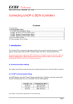
The USS21A (RS-232) serial interface is designed as a 9-pin sub-D socket (EIA standard) and fitted in a housing to be plugged into the inverter (TERMINAL slot). The option
can be plugged in during operation. The transmission rate of the RS-232 interface is
9600 baud.
Connection
Use a commercially-available, serial, shielded interface cable with 1:1 connection to
connect the host computer (PC or notebook) to the USS21A (RS-232) serial interface.
USS21A
PC COM 1-4
5
GND (ground)
5
3
2
TxD
3
2
RxD
max. 5 m (16.5 ft)
9-pin sub D connector (male)
9-pin sub D connector (female)
02399AEN
6
Manual – MOVITRANS® Shell TPS Startup Software Vers. 1.0
Installation
General information
3
Installation
3.1
General information
Installation
3.2
The following section describes how to install the MOVITRANS® SHELL TPS software.
Prerequisites
Hardware
3.3
3
The host computer, on which the MOVITRANS® SHELL TPS startup software is
installed, must meet the following system requirements:
•
Processor: at least Pentium
•
Main memory (RAM): at least 32 MB
•
Available fixed disk storage: 3 MB
•
Graphics card: 800 x 600, 256 colors (recommended: High Color 16-Bit)
•
CD-ROM drive (when installing the CD-ROM)
•
Operating system: Microsoft® Windows® 95, 98, NT 4.0, 2000 or XP
Installation
Instructions
Proceed as follows to install the SHELL TPS software:
1. Insert the supplied data medium in the drive.
2. Select and copy the following files from the "Shell TPS" directory:
•
•
•
•
•
•
SHELLTPS.EXE
MOVILINKSER.DLL
MFC42D.DLL
MFCO42D.DLL
MSVCRTD.DLL
SHELLTPS_Manual.pdf
3. Create a new folder in the target directory for the required drive, e.g.
"C:\Programs\SEW\SHELLTPS"
4. Insert the files you copied in the new folder.
5. If necessary, create shortcuts to "SHELLTPS.exe" on your desktop or in the start
menu.
6. Test your installation by starting the SHELL TPS software. To do so, choose one of
the following options:
•
•
•
Double-click on the "SHELLTPS.EXE" icon in the installation folder
Use the mouse to navigate to the correct item in the start menu
Double-click on the shortcut you created on the desktop
7. Choose one of the following options to open the help file:
•
•
Double-click on the _SHELLTPS_Manual.pdf" icon in the installation folder
Select "?" / "User manual" from the menu bar in the SHELL TPS software
Manual – MOVITRANS® Shell TPS Startup Software Vers. 1.0
7
Installation
Program files
3
3.4
Program files
Overview
The installed files have the following functions:
•
SHELLTPS.EXE:
The "SHELLTPS.EXE" file is an executable program file (.EXE) used to start the software on the host computer (PC or notebook).
•
MOVILINKSER.DLL:
The "MOVILINKSER.DLL" file is needed for serial communication with the connected
MOVITRANS® TPS10A stationary converter.
•
MFC42D.DLL, MFCO42D.DLL and MSVCRTD.DLL:
These files are MFC files (MFC = Microsoft Foundation Class) required for generating the interfaces.
•
SHELLTPS_Manual.pdf:
The "SHELLTPS_Manual.pdf" file contains detailed documentation describing the
design and functions of the startup software.
8
Manual – MOVITRANS® Shell TPS Startup Software Vers. 1.0
Layout
Screen layout
4
Layout
4.1
Screen layout
4
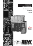
The SHELL TPS software interface is displayed when you start the program:
[1]
[2]
[3]
[4]
55017AEN
[1]
[2]
[3]
[4]
Title bar
Menu bar
Work area
Status bar
Manual – MOVITRANS® Shell TPS Startup Software Vers. 1.0
9
Layout
Interface
4
4.2
Interface
Elements
The interface of the SHELL TPS software includes a title bar, a menu bar, a work or
display area and a status bar. The following section describes the functions and options
available with these elements:
Title bar
The title bar contains the icon and name of the program and the symbols for window
control (minimize, enlarge/reduce, close).
Menu bar
The menu bar displays the software's main menus. You can click on the menu bar to call
up menu items offering additional display or editing options.
Work and display
area
The work area is the space between the menu bar and the status bar. The display
values, startup data and the unit functions of the connected MOVITRANS® TPS10A stationary converter are displayed here.
The work area is divided into two areas: A list of possible display values is displayed on
the left side. Windows containing detailed information are displayed on the right side.
Click on one of the entries in the list on the left to open a window.
In the three groups "Display values", "Startup" and "Unit functions," the following
information windows can be displayed individually or simultaneously:
•
Display values
–
–
–
–
•
Unit data
Process values
Min./Max. values
Fault memory (t-0, t-1, t-2, t-3 and t-4)
Startup
– Compensation
•
Unit functions
– Reset response
Status bar
The current connection status between the SHELL TPS software and the
MOVITRANS® TPS10A stationary converter is displayed in the status bar.
•
Offline
If the status "OFFLINE" is displayed, there is no connection between the host
computer and the MOVITRANS® TPS10A stationary converter.
•
Online
If the status "ONLINE" is displayed, the host computer is connected to the
MOVITRANS® TPS10A stationary converter via a serial interface.
The SHELL TPS software detects the active connection to the stationary converter
and reads in the current process values and unit data.
•
Standby
If the status "STANDBY" is displayed, the connection between the host computer
and the MOVITRANS® TPS10A stationary converter is interrupted.
The SHELL TPS software continues to try to receive and display process values via
the selected serial interface.
If the connection to the MOVITRANS® TPS10A stationary converter is reestablished
again correctly, the current process values can be received and displayed. The
connection status changes back automatically to "ONLINE".
10
Manual – MOVITRANS® Shell TPS Startup Software Vers. 1.0
Layout
Interface
Status change
Function call
4
The connection status changes when the connection is interrupted or if the stationary
converter is switched off:
•
If the SHELL TPS software is no longer able to receive current process values, the
connection status changes automatically from "ONLINE" to "STANDBY".
•
If the connection to the stationary converter is interrupted, the connection status
changes from "ONLINE" to "OFFLINE".
•
If the connection to the stationary converter is reestablished, the connection status
changes from "OFFLINE" or "STANDBY" to "ONLINE".
All information on the display values, startup data and unit functions can either be called
up from the menu bar or from the list in the work area.
The connection between the host computer and the MOVITRANS® TPS10A stationary
converter can be established or separated via the "Connection" menu in the menu bar.
This function is only available in the menu bar.
Window control
You can set the size of the windows as required:
•
To change the width of the windows, click and hold the left mouse button and move
the edge of the window to the left or the right.
•
To change the height of the windows, click and hold the left mouse button and move
the upper or lower edge of the window up or down.
•
Both settings can be changed at the same time by clicking and holding the left mouse
button and moving the right or left-hand corners of the window.
The standard window settings are displayed automatically.
Manual – MOVITRANS® Shell TPS Startup Software Vers. 1.0
11
I
5
Operation
Starting the program
0
5
Operation
5.1
Starting the program
Instructions
Proceed as follows to start the SHELL TPS software:
1. Make sure that the MOVITRANS® TPS10A stationary converter is fitted with a
USS21A (RS-232) serial interface.
2. Connect the host computer (e.g. PC or notebook) to the MOVITRANS® TPS10A
stationary converter using a commercially available serial interface.
3. Start the SHELL TPS software using one of the following options:
•
•
•
5.2
Double-click on the "SHELLTPS.EXE" icon in the installation folder
Use the mouse to navigate to the item you created in the start menu
Double-click on the shortcut you created on the desktop
Establishing a connection
Instructions
Proceed as follows to establish a connection between the SHELL TPS software and the
TPS10A stationary converter:
1. From the main menu, choose "Connection" / "Connect".
The window "Select Interface" is displayed:
10977AEN
2. Select one of the available interfaces.
3. Confirm your selection by clicking "OK".
The connection is established. The current connection status ("ONLINE" or "STANDBY") is displayed in the status bar.
5.3
Ending the connection
Instructions
Proceed as follows to end the connection between the SHELL TPS software and the
TPS10A stationary converter:
1. From the main menu, choose "Connection" / "Disconnect".
The connection is disconnected. The current connection status ("OFFLINE") is displayed in the status bar. The interface that was previously assigned is enabled.
The menu item "Disconnect" is only available when a connection has been established
with the MOVITRANS® TPS10A stationary converter (connection status "ONLINE" or
"STANDBY").
12
Manual – MOVITRANS® Shell TPS Startup Software Vers. 1.0
Operation
Changing the interface
I
5
0
5.4
Changing the interface
Instructions
Proceed as follows to change the interface connection between the SHELL TPS software and the TPS10A stationary converter:
1. From the menu, choose "Connection" / "Change".
The window "Select Interface" is displayed:
10977AEN
2. Select one of the available interfaces.
3. Confirm your selection by clicking "OK".
The connection is established via the selected interface. The current connection
status ("ONLINE" or "STANDBY") is displayed in the status bar. The serial interface
that was previously assigned is enabled.
The menu item "Change" is only available when a connection has been established with
the MOVITRANS® TPS10A stationary converter (connection status "ONLINE" or
"STANDBY").
5.5
Function call
Instructions
Use one of the following options to call up the information windows of the SHELL TPS
software:
•
Select the required menu item from the menu bar.
•
Open the information window by double-clicking on an entry in the list on the lefthand side of the work area.
The "Connection" menu is only available in the menu bar.
5.6
Exiting the program
Instructions
Use one of the following options to exit the SHELL TPS software:
•
From the main menu, choose "Connection" / "Exit".
•
Use the "Close" icon from the window control.
•
Hold the Alt key down and press the "F4" function key.
Manual – MOVITRANS® Shell TPS Startup Software Vers. 1.0
13
kVA
6
i
6
f
n
Functions
Unit data
P Hz
Functions
The following section describes the information windows in the SHELL TPS software
with the display values for start up and the unit functions.
6.1
Unit data
Display
Proceed as follows to display the unit data:
1. Choose the menu item "Unit Data" from the "Display Values" menu.
Alternatively, you can open the information window by double-clicking on the entry
"Unit Data" in the list on the left side of the work area.
The "Unit Data" window is displayed:
[1]
[2]
[3]
55031AEN
[1]
[2]
[3]
Description
Unit type display field
Power section display field
Firmware display field
The following information is displayed in the "Unit data" window:
•
Unit type [1]
The connected unit type is displayed here.
•
Power section [2]
The connected power section is displayed here.
•
Firmware [3]
The firmware version is displayed here.
14
Manual – MOVITRANS® Shell TPS Startup Software Vers. 1.0
Functions
Process values
6.2
kVA
i
f
n
6
P Hz
Process values
Display
Proceed as follows to display the process values:
1. Choose the menu item "Process Values" from the "Display Values" menu.
Alternatively, you can open the information window by double-clicking on the entry
"Process Values" in the list on the left side of the work area.
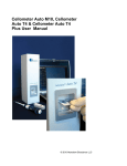
The "Process Values" window is displayed:
[1]
[2]
[3]
[4]
[5]
[6]
[7]
[8]
[9]
[10]
[11]
[12]
[13]
55033AEN
[1]
[2]
[3]
[4]
[5]
[6]
[7]
[8]
[9]
[10]
[11]
[12]
[13]
Output stage display field
Fault status display field
Operating type display field
Setpoint display field
Ramp time display field
Output voltage display field
Output current display field
Load current display field
Load current fluctuation display field
Heat sink temperature display field
Capacity utilization display field
DC link voltage display field
DC link ripple display field
Manual – MOVITRANS® Shell TPS Startup Software Vers. 1.0
15
6
kVA
i
f
n
Functions
Process values
P Hz
Description
The following information is displayed in the "Process Values" window:
•
Output stage [1]
The status of the output stage is displayed here. The following display values are
possible:
– Inhibited
The output stage is currently inhibited.
– Enabled
The output stage is currently enabled.
The status of the output stage can be influenced via binary input DI∅∅ or by a fault.
For more information on this topic, refer to the operating instructions for MOVITRANS®
TPS10A under the section "Operation and Service" (Auto reset function and operating
displays).
•
Fault status [2]
The current fault status is displayed here. The following display values are possible:
– No fault
There is currently no fault.
– Overcurrent
The maximum permitted unit output current has been exceeded. This fault leads
to an output stage inhibit.
– External fault
This fault is triggered when binary input DI∅1 = "0". This fault leads to an output
stage inhibit.
– Overtemperature
The maximum permitted heat sink temperature has been exceeded. This fault
leads to an output stage inhibit.
– Uz undervoltage
The DC link voltage is too low. This fault leads to a fault message at binary output
DΟ∅2.
For more information on the possible causes of the faults and remedial measures, refer
to the operating instructions for MOVITRANS® TPS10A under the section "Operation
and Service" (Auto reset function and operating displays).
•
Operating mode [3]
The current operating mode is displayed here. The following display values are
possible:
– Current control mode 1
The MOVITRANS® TPS10A stationary converter is operating in the mode
"Current control mode 1" (binary input DI∅3 = "0").
– Current control mode 2
The MOVITRANS® TPS10A stationary converter is operating in the mode
"Current control mode 2" (binary input DI∅3 = "1").
16
Manual – MOVITRANS® Shell TPS Startup Software Vers. 1.0
Functions
Process values
•
kVA
i
f
n
6
P Hz
Setpoint [4]
The setpoint selection for the current is displayed here. The following display values
are possible:
– 1.6 A
21.0 % analog
The setpoint specification "Analog input" is made by setting terminals DI∅4 to
"0" and DI∅5 to "0". The analog setpoint at terminal AI11 / AI12 is used as the
setpoint, for example here 21 % IL.
– 3.8 A
50.0 % digital
The setpoint 50 % IL is selected by setting the terminals DI∅3 to "1", DI∅4 to "0"
and DI∅5 to "1".
– 7.5 A
100.0 % digital
The setpoint 100 % IL is selected by setting the terminals DI∅4 to "1" and DI∅5
to "1".
The percentages of the current setpoint are based on the values of the nominal load
current IL. The above values are examples of setpoints for a 4 kW MOVITRANS®
TPS10A stationary converter with a nominal load current of IL = 7.5 Aeff.
•
Ramp time [5]
The ramp time is diplayed here.
•
Output voltage [6]
The r.m.s. value of the output voltage is displayed here.
•
Output current [7]
The r.m.s. value of the output current is displayed here.
•
Load current [8]
The r.m.s. value of the load current is displayed here.
•
Load current fluctuation [9]
The load current fluctuation is diplayed here.
The load current fluctuation represents the fluctuation range of the load current
based on the value of the nominal load current (∆ IL / IL).
•
Heat sink temperature [10]
The heat sink temperature is diplayed here.
Manual – MOVITRANS® Shell TPS Startup Software Vers. 1.0
17
6
kVA
i
f
n
Functions
Process values
P Hz
•
Capacity utilization [11]
The capacity utilization is diplayed here.
The capacity utilization is the present unit output current based on the maximum
permitted unit output current.
When the unit reaches a capacity utilization of 100 %, the unit switches off and
outputs the fault message "Overcurrent".
For more information on this topic, refer to the operating instructions for MOVITRANS®
TPS10A under the section "Operation and Service" (Auto reset function and operating
displays).
•
DC link voltage [12]
The DC link voltage is diplayed here.
•
DC link ripple [13]
The DC link ripple is diplayed here.
The DC link ripple represents the fluctuation range of the DC link voltage.
18
Manual – MOVITRANS® Shell TPS Startup Software Vers. 1.0
Functions
Fault memory
6.3
kVA
i
f
n
6
P Hz
Fault memory
The SHELL TPS software can store several faults. Five fault memories (t-0, t-1, t-2, t-3
and t-4) are available.
The faults are stored in chronological order with the most recent error event being stored
in fault memory t-0. If more than five faults occur, the oldest fault, which is stored in fault
memory t-4, is deleted.
Display
Proceed as follows to display the fault memories:
1. Choose the required fault memory, e.g. "Fault memory t-0", from the "Display
Values" menu.
Alternatively, you can open the information window by double-clicking on the entry
(e.g. "Fault memory t-0") in the list on the left side of the work area.
The window "Fault memory t-0" is displayed:
[1]
[2]
[3]
[4]
[5]
[6]
[7]
[8]
[9]
[10]
[11]
[12]
[13]
55035AEN
[1]
[2]
[3]
[4]
[5]
[6]
[7]
[8]
[9]
[10]
[11]
[12]
[13]
Fault status display field
Output stage display field
Operating type display field
Setpoint display field
Ramp time display field
Output voltage display field
Output current display field
Load current display field
Load current fluctuation display field
Heat sink temperature display field
Capacity utilization display field
DC link voltage display field
DC link ripple display field
Manual – MOVITRANS® Shell TPS Startup Software Vers. 1.0
19
6
kVA
i
f
n
Functions
Fault memory
P Hz
In the event of a
fault
The information that is determined when an error occurs is displayed in the "Fault
memory t-0" window and stored in the fault memory "t-0".
•
Fault status [1]
The current fault status is displayed here.
•
Output stage [2]
The status of the output stage is displayed here.
•
Operating mode [3]
The current operating mode is displayed here.
•
Setpoint [4]
The setpoint selection for the current is displayed here.
•
Ramp time [5]
The ramp time is diplayed here.
•
Output voltage [6]
The r.m.s. value of the output voltage is displayed here.
•
Output current [7]
The r.m.s. value of the output current is displayed here.
•
Load current [8]
The r.m.s. value of the load current is displayed here.
•
Load current fluctuation [9]
The load current fluctuation is diplayed here, e.g. "1.7 ms".
•
Heat sink temperature [10]
The heat sink temperature is diplayed here.
•
Capacity utilization [11]
The capacity utilization is diplayed here.
•
DC link voltage [12]
The DC link voltage is diplayed here.
•
DC link ripple [13]
The DC link ripple is diplayed here.
For more information on the display values and what they mean, refer to the section
"Process values".
20
Manual – MOVITRANS® Shell TPS Startup Software Vers. 1.0
Functions
Min./max. values
6.4
kVA
i
f
n
6
P Hz
Min./max. values
The minimum and maximum process values, recorded since the last time the unit was
switched on, are stored in the "Min./max. values" window.
Display
Proceed as follows to display the min./max. values:
1. Choose the menu item "Min./Max. Values" from the "Display Values" menu.
Alternatively, you can open the information window by double-clicking on the entry
"Min./Max. Values" in the list on the left side of the work area.
The window "Min./Max. Values" is displayed:
[1]
[2]
[3]
[4]
[5]
[6]
[7]
[8]
[9]
55034AEN
[1]
[2]
[3]
[4]
[5]
[6]
[7]
[8]
[9]
Output voltage display field
Output current display field
Load current display field
Load current fluctuation display field
Heat sink temperature display field
Capacity utilization display field
DC link voltage display field
DC link ripple display field
Reset button
Manual – MOVITRANS® Shell TPS Startup Software Vers. 1.0
21
6
kVA
i
f
n
Functions
Min./max. values
P Hz
Description
The following minimum and maximum process values are displayed stored in the
"Min./Max. Values" window:
•
Output voltage [1]
The minimum and maximum values of the output voltage is displayed here.
•
Output current [2]
The minimum and maximum values of the output current is displayed here.
•
Load current [3]
The minimum and maximum values of the load current is displayed here.
•
Load current fluctuation [4]
The minimum and maximum load current fluctuations are displayed here.
•
Heat sink temperature [5]
The minimum and maximum heat sink temperatures are displayed here.
•
Capacity utilization [6]
The minimum and maximum capacity utilization values are displayed here.
•
DC link voltage [7]
The minimum and maximum DC link voltage values are displayed here.
•
DC link ripple [8]
The minimum and maximum DC link ripple values are displayed here.
For more information on the display values and what they mean, refer to the section
"Process values".
Reset
To reset these values to the current process values, press the reset button. Proceed as
follows to reset the min./max. values:
1. Choose the menu item "Min./Max. Values" from the "Display Values" menu.
Alternatively, you can open the information window by double-clicking on the entry
"Min./Max. Values" in the list on the left side of the work area.
The window "Min./Max. Values" is displayed.
2. In the "Min./Max. Values" window, press the "Reset" button [9].
The documented display values are replaced by the current process values.
22
Manual – MOVITRANS® Shell TPS Startup Software Vers. 1.0
Functions
Compensation
6.5
kVA
i
f
n
6
P Hz
Compensation
The "Compensation" window is used during the startup of the MOVITRANS® TPS10A
stationary converter to support the compensation of the line conductor.
To achieve the best measuring results it is important that no real power is transferred
during the measurement.
For more information on this topic, refer to the "MOVITRANS® TAS10A " operating
instructions under the section "Startup" (Startup steps).
Display
Proceed as follows to display the current compensation errors:
1. Choose the menu item "Compensation" from the "Startup" menu.
Alternatively, you can open the information window by double-clicking on the entry
"Compensation" in the list on the left side of the work area.
The "Compensation" window is displayed:
[1]
[2]
[3]
55036AEN
[1]
[2]
[3]
Selection list for the nominal line conductor current
Relativer compensation error display field
Absolute compensation error display field
Manual – MOVITRANS® Shell TPS Startup Software Vers. 1.0
23
6
kVA
i
f
n
Functions
Compensation
P Hz
Description
The following information and compensation errors are displayed in the "Compensation"
window:
•
Nominal line conductor current [1]
The nominal line conductor current at 100 % setpoint is set here.
In the line conductor current field, enter the line conductor current for the system in
question (rated output current of the MOVITRANS® TAS10A transformer module).
This value is used to calculate the absolute compensation error correctly.
•
Relative compensation error [2]
The relative compensation error is displayed here (∆r = output current / load current
in %).
•
Absolute compensation error [3]
The absolute compensation error is displayed here.
Line conductor
current
Proceed as follows to change the nominal line conductor current:
1. Choose the menu item "Compensation" from the "Startup" menu.
Alternatively, you can open the information window by double-clicking on the entry
"Compensation" in the list on the left side of the work area.
The "Compensation" window is displayed.
2. Select the nominal line conductor current [1] at 100 % setpoint.
3. Click on the arrow next to the displayed value and make a selection from the list.
The selected nominal line conductor current (60 A or 85 A) is displayed.
24
Manual – MOVITRANS® Shell TPS Startup Software Vers. 1.0
Functions
Reset response
6.6
kVA
i
f
n
6
P Hz
Reset response
Information on the reset function is displayed in the "Reset response" window.
You can use the reset function to reset errors that occur in the MOVITRANS® TPS10A
stationary converter automatically after a set time.
The auto reset function must not be used in systems where the automatic restart represents a risk of injury to persons or damage to equipment!
For more information on this topic, refer to the operating instructions for MOVITRANS®
TPS10A under the section "Operation and Service" (Auto reset function).
Display
Proceed as follows to display the reset information:
1. Choose "Reset Response" from the "Unit Functions" menu.
Alternatively, you can open the information window by double-clicking on the entry
"Reset Response" in the list on the left side of the work area.
The window "Reset response" is displayed:
[1]
[2]
[3]
55037AEN
[1]
[2]
[3]
Description
Auto reset display field
Reset counter display field
Restart time display field
The following information is displayed in the "Reset response" window:
•
Auto Reset [1]
The current status of the auto reset function is displayed here. The following display
values are possible:
– On
The auto reset function is activated.
– Off
The auto reset function is deactivated.
The auto reset function can be switched on (DI∅2="1") or switched off (DI∅2="0")
via binary input DI∅2.
Manual – MOVITRANS® Shell TPS Startup Software Vers. 1.0
25
6
kVA
i
f
n
Functions
Reset response
P Hz
•
Reset Counter [2]
The number of resets possible is displayed here.
When the auto reset function is activated, up to 3 automatic resets are possible.
•
Restart Time [3]
The restart time; that is the interval between the time when the fault and occurs and
the time it is reset, is displayed here.
The restart time is set to 50 ms.
Fault reset
26
The following errors can be reset automatically when the auto reset function is activated:
•
Overcurrent
•
External fault
•
Overtemperature
Manual – MOVITRANS® Shell TPS Startup Software Vers. 1.0
Index
7
7
Index
A
Application areas ..................................................6
R
Reset response .................................................. 25
C
Changing the interface ........................................13
Compensation .....................................................23
Connection change .............................................11
Connection status ...............................................10
S
Safety notes ......................................................... 4
Screen layout ....................................................... 9
Serial interface USS21A ...................................... 6
SHELL TPS
Offline ...........................................................10
Application areas ........................................... 6
Online ...........................................................10
Changing the interface ................................. 13
Standby ........................................................10
Compensation .............................................. 23
D
Definition ...............................................................6
Designated use .....................................................5
Connection change ...................................... 11
Connection status ........................................ 10
Ending the connection ........................... 12, 13
E
Ending the connection ................................. 12, 13
Establishing a connection ...................................12
Exiting the program .............................................13
Establishing a connection ............................ 12
F
Fault memory ......................................................19
Function call ........................................................11
Functions ............................................................14
Installation ...................................................... 7
Exiting the program ...................................... 13
Fault memory ............................................... 19
Functions ..................................................... 14
Installation files .............................................. 8
Menu bar ...................................................... 10
Min./max. values .......................................... 21
H
Hardware prerequisites .........................................7
Operation ..................................................... 12
I
Installation .............................................................7
Interface ......................................................... 9, 10
Reset response ............................................ 25
Process values ............................................ 15
Screen layout ................................................. 9
Starting the program .................................... 12
M
Menu bar .............................................................10
Min./max. malues ................................................21
Status bar .................................................... 10
O
Operation ............................................................12
Title bar ........................................................ 10
Unit data ...................................................... 14
Function call .................................................11
Work and display area ................................. 10
Starting the program .......................................... 12
Status bar ........................................................... 10
Window control .............................................11
Operational environment .......................................5
T
Title bar .............................................................. 10
P
Prerequisites
Communication ...............................................6
U
Unit data ............................................................. 14
USS21A serial interface option ............................ 6
Hardware ........................................................7
Prerequisites for communication ...........................6
Process values ....................................................15
Program files .........................................................8
Program layout ......................................................9
W
Warning notes ...................................................... 4
Waste disposal ..................................................... 5
Window control ................................................... 11
Work and display area ....................................... 10
Manual – MOVITRANS® SHELL TPS Startup Software Vers. 1.0
27
Address List
Address List
Germany
Headquarters
Production
Sales
Bruchsal
SEW-EURODRIVE GmbH & Co KG
Ernst-Blickle-Straße 42
D-76646 Bruchsal
P.O. Box
Postfach 3023 · D-76642 Bruchsal
Tel. +49 7251 75-0
Fax +49 7251 75-1970
http://www.sew-eurodrive.de
[email protected]
Service
Competence Center
Central
Gear units /
Motors
SEW-EURODRIVE GmbH & Co KG
Ernst-Blickle-Straße 1
D-76676 Graben-Neudorf
Tel. +49 7251 75-1710
Fax +49 7251 75-1711
[email protected]
Central
Electronics
SEW-EURODRIVE GmbH & Co KG
Ernst-Blickle-Straße 42
D-76646 Bruchsal
Tel. +49 7251 75-1780
Fax +49 7251 75-1769
[email protected]
North
SEW-EURODRIVE GmbH & Co KG
Alte Ricklinger Straße 40-42
D-30823 Garbsen (near Hannover)
Tel. +49 5137 8798-30
Fax +49 5137 8798-55
[email protected]
East
SEW-EURODRIVE GmbH & Co KG
Dänkritzer Weg 1
D-08393 Meerane (near Zwickau)
Tel. +49 3764 7606-0
Fax +49 3764 7606-30
[email protected]
South
SEW-EURODRIVE GmbH & Co KG
Domagkstraße 5
D-85551 Kirchheim (near München)
Tel. +49 89 909552-10
Fax +49 89 909552-50
[email protected]
West
SEW-EURODRIVE GmbH & Co KG
Siemensstraße 1
D-40764 Langenfeld (near Düsseldorf)
Tel. +49 2173 8507-30
Fax +49 2173 8507-55
[email protected]
Drive Service Hotline / 24 Hour Service
+49 180 5 SEWHELP
+49 180 5 7394357
Additional addresses for service in Germany provided on request!
France
Production
Sales
Service
Haguenau
SEW-USOCOME
48-54, route de Soufflenheim
B. P. 20185
F-67506 Haguenau Cedex
Tel. +33 3 88 73 67 00
Fax +33 3 88 73 66 00
http://www.usocome.com
[email protected]
Assembly
Sales
Service
Bordeaux
SEW-USOCOME
Parc d’activités de Magellan
62, avenue de Magellan - B. P. 182
F-33607 Pessac Cedex
Tel. +33 5 57 26 39 00
Fax +33 5 57 26 39 09
Lyon
SEW-USOCOME
Parc d’Affaires Roosevelt
Rue Jacques Tati
F-69120 Vaulx en Velin
Tel. +33 4 72 15 37 00
Fax +33 4 72 15 37 15
Paris
SEW-USOCOME
Zone industrielle
2, rue Denis Papin
F-77390 Verneuil I’Etang
Tel. +33 1 64 42 40 80
Fax +33 1 64 42 40 88
Additional addresses for service in France provided on request!
Algeria
Sales
Alger
Réducom
16, rue des Frères Zaghnoun
Bellevue El-Harrach
16200 Alger
Tel. +213 21 8222-84
Fax +213 21 8222-84
Buenos Aires
SEW EURODRIVE ARGENTINA S.A.
Centro Industrial Garin, Lote 35
Ruta Panamericana Km 37,5
1619 Garin
Tel. +54 3327 4572-84
Fax +54 3327 4572-21
[email protected]
Argentina
Assembly
Sales
Service
28
10/2004
Address List
Australia
Assembly
Sales
Service
Melbourne
SEW-EURODRIVE PTY. LTD.
27 Beverage Drive
Tullamarine, Victoria 3043
Tel. +61 3 9933-1000
Fax +61 3 9933-1003
http://www.sew-eurodrive.com.au
[email protected]
Sydney
SEW-EURODRIVE PTY. LTD.
9, Sleigh Place, Wetherill Park
New South Wales, 2164
Tel. +61 2 9725-9900
Fax +61 2 9725-9905
[email protected]
Wien
SEW-EURODRIVE Ges.m.b.H.
Richard-Strauss-Strasse 24
A-1230 Wien
Tel. +43 1 617 55 00-0
Fax +43 1 617 55 00-30
http://sew-eurodrive.at
[email protected]
Brüssel
SEW Caron-Vector S.A.
Avenue Eiffel 5
B-1300 Wavre
Tel. +32 10 231-311
Fax +32 10 231-336
http://www.caron-vector.be
[email protected]
Sao Paulo
SEW-EURODRIVE Brasil Ltda.
Avenida Amâncio Gaiolli, 50
Caixa Postal: 201-07111-970
Guarulhos/SP - Cep.: 07251-250
Tel. +55 11 6489-9133
Fax +55 11 6480-3328
http://www.sew.com.br
[email protected]
Austria
Assembly
Sales
Service
Belgium
Assembly
Sales
Service
Brazil
Production
Sales
Service
Additional addresses for service in Brazil provided on request!
Bulgaria
Sales
Sofia
BEVER-DRIVE GmbH
Bogdanovetz Str.1
BG-1606 Sofia
Tel. +359 2 9532565
Fax +359 2 9549345
[email protected]
Douala
Electro-Services
Rue Drouot Akwa
B.P. 2024
Douala
Tel. +237 4322-99
Fax +237 4277-03
Toronto
SEW-EURODRIVE CO. OF CANADA LTD.
210 Walker Drive
Bramalea, Ontario L6T3W1
Tel. +1 905 791-1553
Fax +1 905 791-2999
http://www.sew-eurodrive.ca
[email protected]
Vancouver
SEW-EURODRIVE CO. OF CANADA LTD.
7188 Honeyman Street
Delta. B.C. V4G 1 E2
Tel. +1 604 946-5535
Fax +1 604 946-2513
[email protected]
Montreal
SEW-EURODRIVE CO. OF CANADA LTD.
2555 Rue Leger Street
LaSalle, Quebec H8N 2V9
Tel. +1 514 367-1124
Fax +1 514 367-3677
[email protected]
Cameroon
Sales
Canada
Assembly
Sales
Service
Additional addresses for service in Canada provided on request!
Chile
Assembly
Sales
Service
Santiago de
Chile
SEW-EURODRIVE CHILE LTDA.
Las Encinas 1295
Parque Industrial Valle Grande
LAMPA
RCH-Santiago de Chile
P.O. Box
Casilla 23 Correo Quilicura - Santiago - Chile
Tel. +56 2 75770-00
Fax +56 2 75770-01
[email protected]
Tianjin
SEW-EURODRIVE (Tianjin) Co., Ltd.
No. 46, 7th Avenue, TEDA
Tianjin 300457
Tel. +86 22 25322612
Fax +86 22 25322611
[email protected]
http://www.sew.com.cn
China
Production
Assembly
Sales
Service
10/2004
29
Address List
China
Assembly
Sales
Service
Suzhou
SEW-EURODRIVE (Suzhou) Co., Ltd.
333, Suhong Middle Road
Suzhou Industrial Park
Jiangsu Province, 215021
P. R. China
Tel. +86 512 62581781
Fax +86 512 62581783
[email protected]
Bogotá
SEW-EURODRIVE COLOMBIA LTDA.
Calle 22 No. 132-60
Bodega 6, Manzana B
Santafé de Bogotá
Tel. +57 1 54750-50
Fax +57 1 54750-44
[email protected]
Zagreb
KOMPEKS d. o. o.
PIT Erdödy 4 II
HR 10 000 Zagreb
Tel. +385 1 4613-158
Fax +385 1 4613-158
[email protected]
Praha
SEW-EURODRIVE CZ S.R.O.
Business Centrum Praha
Luná 591
CZ-16000 Praha 6 - Vokovice
Tel. +420 a220121236
Fax +420 220121237
http://www.sew-eurodrive.cz
[email protected]
Kopenhagen
SEW-EURODRIVEA/S
Geminivej 28-30, P.O. Box 100
DK-2670 Greve
Tel. +45 43 9585-00
Fax +45 43 9585-09
http://www.sew-eurodrive.dk
[email protected]
Tallin
ALAS-KUUL AS
Paldiski mnt.125
EE 0006 Tallin
Tel. +372 6593230
Fax +372 6593231
[email protected]
Lahti
SEW-EURODRIVE OY
Vesimäentie 4
FIN-15860 Hollola 2
Tel. +358 201 589-300
Fax +358 3 780-6211
http://www.sew-eurodrive.fi
[email protected]
Libreville
Electro-Services
B.P. 1889
Libreville
Tel. +241 7340-11
Fax +241 7340-12
Normanton
SEW-EURODRIVE Ltd.
Beckbridge Industrial Estate
P.O. Box No.1
GB-Normanton, West- Yorkshire WF6 1QR
Tel. +44 1924 893-855
Fax +44 1924 893-702
http://www.sew-eurodrive.co.uk
[email protected]
Athen
Christ. Boznos & Son S.A.
12, Mavromichali Street
P.O. Box 80136, GR-18545 Piraeus
Tel. +30 2 1042 251-34
Fax +30 2 1042 251-59
http://www.boznos.gr
[email protected]
Hong Kong
SEW-EURODRIVE LTD.
Unit No. 801-806, 8th Floor
Hong Leong Industrial Complex
No. 4, Wang Kwong Road
Kowloon, Hong Kong
Tel. +852 2 7960477 + 79604654
Fax +852 2 7959129
[email protected]
Colombia
Assembly
Sales
Service
Croatia
Sales
Service
Czech Republic
Sales
Denmark
Assembly
Sales
Service
Estonia
Sales
Finland
Assembly
Sales
Service
Gabon
Sales
Great Britain
Assembly
Sales
Service
Greece
Sales
Service
Hong Kong
Assembly
Sales
Service
30
10/2004
Address List
Hungary
Sales
Service
Budapest
SEW-EURODRIVE Kft.
H-1037 Budapest
Kunigunda u. 18
Tel. +36 1 437 06-58
Fax +36 1 437 06-50
[email protected]
Assembly
Sales
Service
Baroda
SEW-EURODRIVE India Pvt. Ltd.
Plot No. 4, Gidc
Por Ramangamdi · Baroda - 391 243
Gujarat
Tel. +91 265 2831086
Fax +91 265 2831087
[email protected]
Technical Offices
Bangalore
SEW-EURODRIVE India Private Limited
308, Prestige Centre Point
7, Edward Road
Bangalore
Tel. +91 80 22266565
Fax +91 80 22266569
[email protected]
Mumbai
SEW-EURODRIVE India Private Limited
312 A, 3rd Floor, Acme Plaza
Andheri Kurla Road, Andheri (E)
Mumbai
Tel. +91 22 28348440
Fax +91 22 28217858
[email protected]
Dublin
Alperton Engineering Ltd.
48 Moyle Road
Dublin Industrial Estate
Glasnevin, Dublin 11
Tel. +353 1 830-6277
Fax +353 1 830-6458
Tel-Aviv
Liraz Handasa Ltd.
Ahofer Str 34B / 228
58858 Holon
Tel. +972 3 5599511
Fax +972 3 5599512
[email protected]
Milano
SEW-EURODRIVE di R. Blickle & Co.s.a.s.
Via Bernini,14
I-20020 Solaro (Milano)
Tel. +39 2 96 9801
Fax +39 2 96 799781
[email protected]
Abidjan
SICA
Ste industrielle et commerciale pour l’Afrique
165, Bld de Marseille
B.P. 2323, Abidjan 08
Tel. +225 2579-44
Fax +225 2584-36
Toyoda-cho
SEW-EURODRIVE JAPAN CO., LTD
250-1, Shimoman-no,
Iwata
Shizuoka 438-0818
Tel. +81 538 373811
Fax +81 538 373814
[email protected]
Ansan-City
SEW-EURODRIVE KOREA CO., LTD.
B 601-4, Banweol Industrial Estate
Unit 1048-4, Shingil-Dong
Ansan 425-120
Tel. +82 31 492-8051
Fax +82 31 492-8056
[email protected]
Riga
SIA Alas-Kuul
Katlakalna 11C
LV-1073 Riga
Tel. +371 7139386
Fax +371 7139386
[email protected]
Beirut
Gabriel Acar & Fils sarl
B. P. 80484
Bourj Hammoud, Beirut
Tel. +961 1 4947-86
+961 1 4982-72
+961 3 2745-39
Fax +961 1 4949-71
[email protected]
India
Ireland
Sales
Service
Israel
Sales
Italy
Assembly
Sales
Service
Ivory Coast
Sales
Japan
Assembly
Sales
Service
Korea
Assembly
Sales
Service
Latvia
Sales
Lebanon
Sales
10/2004
31
Address List
Lithuania
Sales
Alytus
UAB Irseva
Merkines g. 2A
LT-62252 Alytus
Tel. +370 315 79204
Fax +370 315 56175
[email protected]
www.sew-eurodrive.lt
Brüssel
CARON-VECTOR S.A.
Avenue Eiffel 5
B-1300 Wavre
Tel. +32 10 231-311
Fax +32 10 231-336
http://www.caron-vector.be
[email protected]
Johore
SEW-EURODRIVE SDN BHD
No. 95, Jalan Seroja 39, Taman Johor Jaya
81000 Johor Bahru, Johor
West Malaysia
Tel. +60 7 3549409
Fax +60 7 3541404
[email protected]
Queretaro
SEW-EURODRIVE, Sales and Distribution,
S. A. de C. V.
Privada Tequisquiapan No. 102
Parque Ind. Queretaro C. P. 76220
Queretaro, Mexico
Tel. +52 442 1030-300
Fax +52 442 1030-301
[email protected]
Casablanca
S. R. M.
Société de Réalisations Mécaniques
5, rue Emir Abdelkader
05 Casablanca
Tel. +212 2 6186-69 + 6186-70 + 618671
Fax +212 2 6215-88
[email protected]
Rotterdam
VECTOR Aandrijftechniek B.V.
Industrieweg 175
NL-3044 AS Rotterdam
Postbus 10085
NL-3004 AB Rotterdam
Tel. +31 10 4463-700
Fax +31 10 4155-552
http://www.vector.nu
[email protected]
Auckland
SEW-EURODRIVE NEW ZEALAND LTD.
P.O. Box 58-428
82 Greenmount drive
East Tamaki Auckland
Tel. +64 9 2745627
Fax +64 9 2740165
[email protected]
Christchurch
SEW-EURODRIVE NEW ZEALAND LTD.
10 Settlers Crescent, Ferrymead
Christchurch
Tel. +64 3 384-6251
Fax +64 3 384-6455
[email protected]
Moss
SEW-EURODRIVE A/S
Solgaard skog 71
N-1599 Moss
Tel. +47 69 241-020
Fax +47 69 241-040
[email protected]
Lima
SEW DEL PERU MOTORES REDUCTORES
S.A.C.
Los Calderos, 120-124
Urbanizacion Industrial Vulcano, ATE, Lima
Tel. +51 1 3495280
Fax +51 1 3493002
[email protected]
Lodz
SEW-EURODRIVE Polska Sp.z.o.o.
ul. Techniczna 5
PL-92-518 Lodz
Tel. +48 42 67710-90
Fax +48 42 67710-99
http://www.sew-eurodrive.pl
[email protected]
Luxembourg
Assembly
Sales
Service
Malaysia
Assembly
Sales
Service
Mexico
Assembly
Sales
Service
Morocco
Sales
Netherlands
Assembly
Sales
Service
New Zealand
Assembly
Sales
Service
Norway
Assembly
Sales
Service
Peru
Assembly
Sales
Service
Poland
Assembly
Sales
Service
32
10/2004
Address List
Portugal
Assembly
Sales
Service
Coimbra
SEW-EURODRIVE, LDA.
Apartado 15
P-3050-901 Mealhada
Tel. +351 231 20 9670
Fax +351 231 20 3685
http://www.sew-eurodrive.pt
[email protected]
Bucuresti
Sialco Trading SRL
str. Madrid nr.4
011785 Bucuresti
Tel. +40 21 230-1328
Fax +40 21 230-7170
[email protected]
St. Petersburg
ZAO SEW-EURODRIVE
P.O. Box 263
RUS-195220 St. Petersburg
Tel. +7 812 5357142 +812 5350430
Fax +7 812 5352287
http://www.sew-eurodrive.ru
[email protected]
Dakar
SENEMECA
Mécanique Générale
Km 8, Route de Rufisque
B.P. 3251, Dakar
Tel. +221 849 47-70
Fax +221 849 47-71
[email protected]
Beograd
DIPAR d.o.o.
Kajmakcalanska 54
SCG-11000 Beograd
Tel. +381 11 3088677 / +381 11
3088678
Fax +381 11 3809380
[email protected]
Singapore
SEW-EURODRIVE PTE. LTD.
No 9, Tuas Drive 2
Jurong Industrial Estate
Singapore 638644
Tel. +65 68621701
Fax +65 68612827
[email protected]
Sered
SEW-Eurodrive SK s.r.o.
Trnavska 920
SK-926 01 Sered
Tel. +421 31 7891311
Fax +421 31 7891312
[email protected]
Celje
Pakman - Pogonska Tehnika d.o.o.
UI. XIV. divizije 14
SLO – 3000 Celje
Tel. +386 3 490 83-20
Fax +386 3 490 83-21
[email protected]
Johannesburg
SEW-EURODRIVE (PROPRIETARY) LIMITED
Eurodrive House
Cnr. Adcock Ingram and Aerodrome Roads
Aeroton Ext. 2
Johannesburg 2013
P.O.Box 90004
Bertsham 2013
Tel. +27 11 248-7000
Fax +27 11 494-3104
[email protected]
Capetown
SEW-EURODRIVE (PROPRIETARY) LIMITED
Rainbow Park
Cnr. Racecourse & Omuramba Road
Montague Gardens
Cape Town
P.O.Box 36556
Chempet 7442
Cape Town
Tel. +27 21 552-9820
Fax +27 21 552-9830
Telex 576 062
[email protected]
Durban
SEW-EURODRIVE (PROPRIETARY) LIMITED
2 Monaceo Place
Pinetown
Durban
P.O. Box 10433, Ashwood 3605
Tel. +27 31 700-3451
Fax +27 31 700-3847
[email protected]
Romania
Sales
Service
Russia
Sales
Senegal
Sales
Serbia and Montenegro
Sales
Singapore
Assembly
Sales
Service
Slovakia
Sales
Slovenia
Sales
Service
South Africa
Assembly
Sales
Service
10/2004
33
Address List
Spain
Assembly
Sales
Service
Bilbao
SEW-EURODRIVE ESPAÑA, S.L.
Parque Tecnológico, Edificio, 302
E-48170 Zamudio (Vizcaya)
Tel. +34 9 4431 84-70
Fax +34 9 4431 84-71
[email protected]
Jönköping
SEW-EURODRIVE AB
Gnejsvägen 6-8
S-55303 Jönköping
Box 3100 S-55003 Jönköping
Tel. +46 36 3442-00
Fax +46 36 3442-80
http://www.sew-eurodrive.se
[email protected]
Basel
Alfred lmhof A.G.
Jurastrasse 10
CH-4142 Münchenstein bei Basel
Tel. +41 61 41717-17
Fax +41 61 41717-00
http://www.imhof-sew.ch
[email protected]
Chon Buri
SEW-EURODRIVE (Thailand) Ltd.
Bangpakong Industrial Park 2
700/456, Moo.7, Tambol Donhuaroh
Muang District
Chon Buri 20000
Tel. +66 38 454281
Fax +66 38 454288
[email protected]
Tunis
T. M.S. Technic Marketing Service
7, rue Ibn EI Heithem
Z.I. SMMT
2014 Mégrine Erriadh
Tel. +216 1 4340-64 + 1 4320-29
Fax +216 1 4329-76
Istanbul
SEW-EURODRIVE
Hareket Sistemleri Sirketi
Bagdat Cad. Koruma Cikmazi No. 3
TR-34846 Maltepe ISTANBUL
Tel. +90 216 4419163 + 216 4419164 +
216 3838014
Fax +90 216 3055867
[email protected]
Production
Assembly
Sales
Service
Greenville
SEW-EURODRIVE INC.
1295 Old Spartanburg Highway
P.O. Box 518
Lyman, S.C. 29365
Tel. +1 864 439-7537
Fax Sales +1 864 439-7830
Fax Manuf. +1 864 439-9948
Fax Ass. +1 864 439-0566
Telex 805 550
http://www.seweurodrive.com
[email protected]
Assembly
Sales
Service
San Francisco
SEW-EURODRIVE INC.
30599 San Antonio St.
Hayward, California 94544-7101
Tel. +1 510 487-3560
Fax +1 510 487-6381
[email protected]
Philadelphia/PA
SEW-EURODRIVE INC.
Pureland Ind. Complex
2107 High Hill Road, P.O. Box 481
Bridgeport, New Jersey 08014
Tel. +1 856 467-2277
Fax +1 856 845-3179
[email protected]
Dayton
SEW-EURODRIVE INC.
2001 West Main Street
Troy, Ohio 45373
Tel. +1 937 335-0036
Fax +1 937 440-3799
[email protected]
Dallas
SEW-EURODRIVE INC.
3950 Platinum Way
Dallas, Texas 75237
Tel. +1 214 330-4824
Fax +1 214 330-4724
[email protected]
Sweden
Assembly
Sales
Service
Switzerland
Assembly
Sales
Service
Thailand
Assembly
Sales
Service
Tunisia
Sales
Turkey
Assembly
Sales
Service
USA
Additional addresses for service in the USA provided on request!
Venezuela
Assembly
Sales
Service
34
Valencia
SEW-EURODRIVE Venezuela S.A.
Av. Norte Sur No. 3, Galpon 84-319
Zona Industrial Municipal Norte
Valencia, Estado Carabobo
Tel. +58 241 832-9804
Fax +58 241 838-6275
[email protected]
[email protected]
10/2004
SEW-EURODRIVE – Driving the world
Gearmotors \ Industrial Gear Units \ Drive Electronics \ Drive Automation \ Services
How we’re driving the world
With people who
think fast and
develop the
future with you.
With a worldwide
service network that is
always close at hand.
With drives and controls
that automatically
improve your productivity.
With comprehensive
knowledge in virtually
every branch of
industry today.
With uncompromising
quality that reduces the
cost and complexity of
daily operations.
SEW-EURODRIVE
Driving the world
With a global presence
that offers responsive
and reliable solutions.
Anywhere.
With innovative
technology that solves
tomorrow’s problems
today.
With online information
and software updates,
via the Internet, available
around the clock.
SEW-EURODRIVE GmbH & Co KG
P.O. Box 3023 · D-76642 Bruchsal / Germany
Phone +49 7251 75-0 · Fax +49 7251 75-1970
[email protected]
www.sew-eurodrive.com