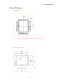
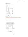
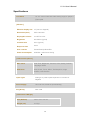
1
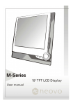
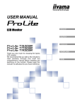
PV520 User’s Manual
U s e r ’ s
M a n u a l
PV520
1
PV520 User’s Manual
Table of Contents
1. Important Safety Instructions
3
2. Introduction
8
3. Recommended Use of the Monitor
14
4. Controls and Adjustments
16
5. Energy Declaration
22
6. Trouble Shooting
23
7. Technical Information
25
8. Product Overview
27
9. Specifications
30
2
PV520 User’s Manual
Important Safety Instructions
FCC Statement
This equipment has been tested to comply with the limits for a class B digital
device, pursuant to Part 15 of the FCC rules. These limits are designed to
provide reasonable protection against harmful interference in a residential
installation. This equipment generates, uses and can radiate radio frequency
energy and, if not installed and used in accordance with the instructions, may
cause harmful interference to radio communications. However, there is no
guarantee that interference will not occur in a particular installation. If this
equipment does cause harmful interference to radio or television reception,
which can be determined by turning the equipment off and on, the user is
encouraged to try to correct the interference by one or more of the following
measures:
•
Relocate the receiving antenna.
•
Increase the separation between the equipment and the receiver.
•
Connect the equipment into an outlet on a circuit different from that to
which the receiver is connected.
•
Consult the dealer or an experienced radio/TV technician for help.
Warning:
If a shielded-type power cord is supplied with this monitor, it is required in
order to meet FCC emission limits and to prevent interference with nearby
radio and television reception. Only shielded cables should be used to
connect I/O devices to this equipment. You are cautioned that changes or
modifications not expressly approved by the party responsible for compliance
could void your authority to operate the equipment.
CE Statement
This device complies with the requirements of EMC (Electromagnetic
Compatibility), and with Low Voltage directive.
3
PV520 User’s Manual
TCO'99
TCO99 compliant monitors must be compliant with TCO99 which is more
stringent than MPRII. The purchase of TCO99 compliant monitors contributes
to reducing the burden on the environment and also to the further
development of environmentally adapted electronics products.
Why do we have environmentally labelled computers?
In many countries, environmental labelling has become an established
method-for encouraging the adaptation of goods and services to the
environment. The main problem, as far as computers and other electronics
equipment are concerned, is that environmentally harmful substances are
used both in the products and during their manufacture. Since it is not so far
possible to satisfactorily recycle the majority of electronics equipment, most of
these potentially damaging substances sooner or later enter nature.
There are also other characteristics of a computer, such as energy
consumption levels, that are important from the viewpoints of both the work
(internal) and natural (external) environments. Since all methods of electricity
generation have a negative effect on the environment (e.g. acidic and
climate-influencing emissions, radioactive waste), it is vital to save energy.
Electronics equipment in offices is often left running continuously and thereby
consumes a lot of energy.
What does labelling involve?
This product meets the requirements for the TCO'99 scheme which provides
for international and environmental labelling of personal computers. The
labelling scheme was developed as a joint effort by the TCO (The Swedish
Confederation of Professional Employees), Svenska Naturskyddsforeningen
(The Swedish Society for Nature Conservation) and Statens Energimyndighet
(The Swedish National Energy Administration).
Approval requirements cover a wide range of issues: environment,
ergonomics, usability, emission of electric and magnetic fields, energy
consumption and electrical and fire safety.
The environmental demands impose restrictions on the presence and use of
heavy metals, brominated and chlorinated flame retardants, CFCs (freons)
and chlorinated solvents, among other things. The product must be prepared
for recycling and the manufacturer is obliged to have an environmental policy
which must be adhered to in each country where the company implements its
operational policy.
4
PV520 User’s Manual
The energy requirements include a demand that the computer and/or display,
after a certain period of inactivity, shall reduce its power consumption to a
lower level in one or more stages. The length of time to reactivate the
computer shall be reasonable for the user.
Labelled products must meet strict environmental demands, for example, in
respect of the reduction of electric and magnetic fields, physical and visual
ergonomics and good usability. Below you will find a brief summary of the
environmental requirements met by this product. The complete environmental
criteria document may be ordered from:
TCO Development
SE-114 94 Stockholm, Sweden
Fax: +46 8 782 92 07
Email (Internet): [email protected]
Current information regarding TCO'99 approved and labelled products may
also be obtained via the Internet, using the address: http://www.tco-info.com/
Environmental requirements
Flame retardants
Flame retardants are present in printed circuit boards, cables, wires, casings
and housings. There purpose is to prevent, or at least to delay the spread of
fire. Up to 30% of the plastic in a computer casing can consist of flame
retardant substances. Most flame retardants contain bromine or chloride, and
those flame retardants are chemically related to another group of
environmental toxins, PCBs. Both the flame retardants containing bromine or
chloride and the PCBs are suspected of giving rise to severe health effects,
including reproductive damage in fish-eating birds and mammals, due to the
bio-accumulative* processes. Flame retardants have been found in human
blood and researchers fear that disturbances in foetus development may
occur.
The relevant TCO'99 demand requires that plastic components weighing
more than 25 grams must not contain flame retardants with organically bound
bromine or chlorine. Flame retardants are allowed in the printed circuit boards
since no substitutes are available.
5
PV520 User’s Manual
Cadmium**
Cadmium is present in rechargeable batteries and in the colour-generating
layers of certain computer displays. Cadmium damages the nervous system
and is toxic in high doses. The relevant TCO'99 requirement states that
batteries, the colour-generating layers of display screens and the electrical or
electronics components must not contain any cadmium.
Mercury**
Mercury is sometimes found in batteries, relays and switches. It damages the
nervous system and is toxic in high doses. The relevant TCO'99 requirement
states that batteries may not contain any mercury. It also demands that
mercury is not present in any of the electrical or electronics components
associated with the labelled unit.
CFCs (freons)
The relevant TCO'99 requirement states that neither CFCs nor HCFCs may
be used during the manufacture and assembly of the product. CFCs (freons)
are sometimes used for washing printed circuit boards. CFCs break down
ozone and thereby damage the ozone layer in the stratosphere, causing
increased reception on earth of ultraviolet light with e.g. increased risks of skin
cancer (malignant melanoma) as a consequence.
Lead**
Lead can be found in picture tubes, display screens, solders and capacitors.
Lead damages the nervous system and in higher doses, causes lead
poisoning. The relevant TCO'99 requirement permits the inclusion of lead
since no replacement has yet been developed.
*Bio-accumulative is defined as substances which accumulate within living
organisms.
** Lead, Cadmium and Mercury are heavy metals which are Bio-accumulative.
Safety Precautions
Please read the following instructions carefully. This manual should be
retained for future reference.
1. To clean the LCD Monitor screen make sure the Monitor is in the power off
mode. Unplug the Monitor from its power source before cleaning it. Stand
away from the LCD Monitor and spray cleaning solution onto a rag. Without
applying excessive pressure clean the screen with the slightly dampened rag.
6
PV520 User’s Manual
2. Do not place your LCD Monitor near a window. Exposing the Monitor to rain,
water, moisture or sunlight can severely damage it.
3. Do not place anything on top of the Monitor/PC signal cord. Make sure the
cord is placed in an area where it will not be stepped on.
4. Do not apply pressure to the LCD screen. Excessive pressure may cause
permanent damage to the display.
5. Do not remove the cover or attempt to service this unit by yourself. You may
void the warranty. Servicing of any nature should only be performed by an
authorised technician.
6. Safe storage of the LCD Monitor is in a range of minus 20 to plus 65
degrees Celsius. Storing your LCD Monitor outside this range could result in
permanent damage.
7. If any of the following occurs immediately unplug your Monitor and call an
authorized technician.
•
The power or Monitor-to-PC signal cord is frayed or damaged.
•
Liquid has been spilled into the Monitor, or it has been exposed to
rain.
•
The Monitor has been dropped or the case has been damaged.
8. For use only with power supply:
•
Li Shin(LSE) LSE9901B1250
•
Portrans UP06031120A
•
Lien Chang BSA-35-115
Notice : Actual safety specifications please refer to the label on the back
of monitor.
7
PV520 User’s Manual
Introduction
Product Description
Congratulations on purchasing this new generation monitor. Your LCD
monitor incorporates high quality display into a small lightweight module. It
has power- saving capabilities and emits no X-ray radiation.
The features are:
•
15" TFT Liquid Crystal Display
•
Compatible with IBM VGA, VESA
•
Direct RGB input
•
XGA 1024x768 resolution, up to 16.7M colors
•
Lightweight compact design, weighing less than 6.5Kg
•
DPMS (power saving)
•
Universal adapter power supply
•
Anti-glare display
•
On-Screen Display (OSD) controls and adjustments
8
PV520 User’s Manual
Package Overview
Your monitor package contains:
LCD Monitor
User's Guide /
Driver CD
Power Cord
Power Adapter
VGA Signal Cable
CAUTION
Keep the shipping carton in case the need arises to store or transport the unit.
Let the LCD lie on its face when you put it into the carton.
9
PV520 User’s Manual
Installation & Remove
1-1. Installing the Portrait
10
PV520 User’s Manual
1-2. Remove the Portrait
11
PV520 User’s Manual
2-1. Installing the Wall Mount Adapter*
12
PV520 User’s Manual
2-2. Remove the Wall Mount Adapter*
* The Wall Mount Adapter is a optional item.
13
PV520 User’s Manual
Recommended Use of the Monitor
Power
Use the type of power indicated on the marking label.
Plugs
Do not remove any of the prongs of the monitor's three-pronged power plug.
Disconnect the power plug from the AC outlet if you are not going to use it for
an indefinite period of time.
Power cords
Use the proper power cord with correct attachment plug type. If the power
source is 120 V AC, use a power cord that has UL and CSA approvals. If the
power source is a 240 V AC supply, use the tandem (T blade) type attachment
plug with ground conductor power cord that meets the respective European
country's safety regulations, such as VDE for Germany.
We recommend using the power cord supplied with the product. However, if
another type of power cord is required power cord H05VV-F or VW-1, 18AWG
x 3G should be used.
Do not overload wall outlets or power cords. Ensure that the total of all units
plugged into the wall outlet does not exceed 7 amperes.
Ensure that the total ampere ratings on all units plugged into the extension
cord is not above the cord's rating.
If the power supply cord which came with your monitor is to be connected to
the PC instead of the wall outlet, this equipment should be used with UL/TUV
approved computers with receptacle rated 100~240V AC, 50/60Hz, 1.0A
(minimum).
14
PV520 User’s Manual
Do not allow anything to rest on the power cord. Do not locate this product
where persons will walk on the cord.
Environment
Place the monitor on a flat level surface.
Place the monitor in a well-ventilated place.
Keep the monitor away from: rain or water overly hot, cold or humid places
sunlight dusty surroundings equipment that generates strong magnetic fields.
15
PV520 User’s Manual
Controls and Adjustments
Once you have installed this monitor with your system, please read the
instructions in this section, they give you some guidelines on how to use the
monitor more efficiently. And lead you through the various functions of the
user controls and explain how to adjust the monitor to your personal
preference.
Front User Controls
(1) Enter "
" button
To display the OSD manual and select functions.
(2) Down " " button
To adjust the selected OSD function or the brightness directly.
(3) Up " " button
To adjust the selected OSD function or the contrast directly.
(4) "ESC" button
To close the OSD manual and to escape function.
16
PV520 User’s Manual
(5) Power LED Indicator
As long as the monitor is powered, this indicator is lit. In normal operation, it
lights green. While in power saving mode, the indicator will turn to amber.
(6) Power Switch
To turn the monitor On or Off.
On Screen Display (OSD) Main menu
1. Press "
" to open the OSD main menu.
2. Use the " " and " " arrows to move through the displayed functions.
3. Press "
" to confirm your selected function.
Brightness
Press the " " button to enter the brightness, and press the " " or " " button to
increase or decrease the brightness level, then press " ESC" button to exit.
Contrast
Press the " " button to enter the contrast, and press the " " or " " button to
increase or decrease the contract level, then press " ESC" button to exit.
17
PV520 User’s Manual
1. Auto-Tune
Press "
" button, the system will automatically adjust the clock, phase,
H-position and V-position values for optimal settings.
ADVANCE AUTO TUNE PATTERN PROGRAM USING GUIDE
•
As some VGA Card doesn't match the VESA standard. It can't out-put 0.7 V p-p VESA
standard. Therefore, we need "ADVANCE AUTO TUNE PATTERN PROGRAM" to
modify the parameters of monitor to match different output level of VGA card.
•
Win_pat.exe (This file includes in the folder "driver" of CD Title "Interactive User's
Manual") is used for Windows95 or 98 currently display mode adjustment. It will adjust
the VGA input level and video quality to optimize.
•
Dos_pat.exe (This file includes in the folder "driver" of CD Title "Interactive User's
Manual") is used for 720x400 70Hz & 640x 350 70Hz under DOS mode adjustment. It
will adjust the VGA input level and video quality to optimize.
•
For the adjustment, please execute the program, then processing the "Auto Tune"
function in the OSD menu.
2. Color
18
PV520 User’s Manual
You can choose either the 6500°K, 9300°K colour temperature mode or User
mode to store your user defined color settings.
User Mode
•
Press "
•
Press the " " or " " button to select the R/G/B gain, then press "
" button to enter User mode.
"
button to proceed.
•
Finally, press "ESC" button to leave this function.
3. Quality
Here are some items can be adjusted as below, please press "
item menu.
19
" enter the
PV520 User’s Manual
•
Size:
Press the " " or " " button to adjust the width of the screen to a
maximum.
•
Phase:
Press the " " or " " button to reduce the noise on the screen.
•
Focus:
Press the " " or " " button to adjust the focus of the screen with the
resolution is lower than 1024x768.
•
Dither:
Press the " " or " " button to enable true color.
•
Text/Gfx (Graphics):
Press the " " or " " button to select VGA Text mode 720x400 &
720x350 or VGA Graphics mode 640x400 & 640x350 to get better
picture performance.
4. Position
To adjust the Image or OSD position.
20
PV520 User’s Manual
Image Position or OSD Position
•
H - Position: Press the " " or " " button to reposition of the picture or
the OSD window to the right or left.
•
V - Position: Press the" " button to moves the picture or the OSD
window upwards and " " to move them downwards.
•
Center: The Image or OSD window will be adjusted automatically on
center of the screen.
5. Language
Press the " " or " " button to select between English, French, Italian, Spanish
or German languages.
6. Recall
Press the " " or " " button to select "Yes" or "No".
Choosing Recall to callback all the settings for the current Input Signal mode
to factory preset.
21
PV520 User’s Manual
Energy Declaration
This monitor is equipped with a function for saving energy, which supports the
VESA Display Power Management Signaling (DPMS) standard. This means
that the monitor must be connected to a computer, which also supports the
VESA DPMS standard to fulfill the requirements of the NUTEK specification
803299/94/96. The time settings for switching to a power saving mode are
adjusted from the system unit by software. From the first indication of inactivity
to power saving position A2 the total time must not be set to more than 70
minutes.
1. VESA Power-Management Proposal
VESA DPMS Standard
H. sync
V. sync
Video
State
Off
On
Blank
Stand-by
On
Off
Blank
Suspend
Off
Off
Blank
Off
2. Power Consumption (120/230 Vac)
NUTEK
Normal operation
Power Saving
Position A1
Power Saving
Position A2
VESA
LED
Power
state
indicator
Consumption
On
Green
< 35W
Suspend
Amber
< 5W
Off
Amber
< 5W
22
PV520 User’s Manual
Trouble Shooting
If you are experiencing trouble with the LCD display refer to the following. If the
problem persists please contact your local dealer or our service center.
The monitor does
Check if the monitor is turned on.
not respond after
you turn on the
Turn off the power and check the monitor power cord and
system.
signal cable are properly connected.
The characters on
the screen are
dim.
Refer to the Controls and Adjustments section to adjust
the brightness (BRIGHTNESS on the OSD sub-menu.) .
The screen is
During use the monitor screen may automatically turn off
blank.
as a result of the Power Saving feature. Press any key to
see if the screen comes back.
Refer to the Controls and Adjustments section to adjust
the brightness (BRIGHTNESS on the OSD sub-menu.) .
The screen
Turn off the monitor and turn it on again.
flashes when it
initializes.
Refer to the Controls and Adjustments section to reload
the default setting (RESET on the OSD main-menu.) .
Partial image or
Check to see if the resolution of your computer is higher
incorrectly
than that of the LCD display.
displayed image
Reconfigure the resolution of your computer to make it
less than or equal to 1024 x 768.
Image has vertical
Use "Size" to make an adjustment.
line bars
Check and reconfigure the display mode of the vertical
refresh rate of your graphic card to make it compatible
with the LCD display.
23
PV520 User’s Manual
Image has
Use "Phase" to make an adjustment.
horizontal
flickering lines
IF input signals are 720x350 and 640x400, into OSD
Control Text/ Graphics item switch to other mode.
Signal out of
When the input signal is outside the normal specifications
Range
the screen will display an "Unsupported Mode "
message.
No Signal Input
The "No Signal Input" message indicates that the cable
may not be plugged property into the host system.
WARNING:
Do not disassemble the monitor. Contact your dealer if needed.
24
PV520 User’s Manual
Technical Information
Compatibility
This LCD monitor supports multiple operating platforms such as IBM
compatible computers. This section provides you with detailed information on
pin assignment of the D-Sub connector and the preset timing chart of the
prevailing video standards.
Pin Assignments
Male Mini D-15 Connector
Signal
15 Pin Mini D-Sub
Red Video
1
Green Video
2
Blue Video
3
Horizontal Sync
13
Vertical Sync
14
Ground
5, 6, 7, 8, 10, 11
No Connection
4, 9
SDA (DDC)
12
SCL (DDC)
15
25
PV520 User’s Manual
Video Modes
Resolution
VCLK(MHz)
Horizontal
Refresh
Frequency
Rate
(KHz)
(Hz)
Standard
640*350
25.175
31.470
70.000
IBM VGA
720*400
28.322
31.469
70.000
IBM VGA
640*480
25.175
31.470
59.940
IBM VGA
640*480
30.240
37.861
72.000
VESA
640*480
31.500
37.500
75.000
VESA
800*600
40.000
37.879
60.000
VESA
800*600
50.000
48.077
72.000
VESA
800*600
49.500
46.880
75.000
VESA
1024*768
65.000
48.363
60.000
VESA
1024*768
75.000
56.476
70.000
VESA
1024*768
78.750
60.020
75.000
VESA
26
PV520 User’s Manual
Product Overview
Pivot Function
You can turn the LCD panel right 90 degree for particular viewing.
Front View (unit: mm)
27
PV520 User’s Manual
Side View (unit: mm)
For viewing clarity, you can tilt the LCD panel forward (up to 5 degrees) or
backward (up to 20 degrees)
Rear View (unit: mm)
28
PV520 User’s Manual
Specifications
LCD Panel
15" TFT LCD module with wide-viewing angle, 0.3(H)x0.3
(V)mm pixel
[ Monitor ]
Effective display size
15" (38.1cm diagonal)
Resolution (max.)
XGA 1024x768
Displayable colours
16.7M True color
Brightness
200 Cd/m2 (typical)
Contrast ratio
350:1 (typical)
Response time
40ms
User controls
Power/Enter/Up/Down/Esc
Power Consumption
35W Max. <5W Power Saving
[ OSD control options ]
Main menu
Auto-Tune, Brightness, Contrast, Color, Quality, Position,
Language, Recall
Sub-menu
Size, Phase, Focus, Dither, Text/Graphics, Image
Position, OSD Position
Input signal
Analog 0.7V peak to peak separate TTL Positive or
Negative
Power Supply
100~240 VAC, 50/60 Hz (automatically)
Plug & Play
DDC 1/2B
[ Dimension & Weight ]
Size (WxDxH)
383 x 172 x 373 mm
Weight (net)
5.5 Kgs
30
PV520 User’s Manual
[ Operating Environment ]
Temperature
5°C ~ 35°C
Humidity
20% ~ 80% (non-condensing)
Altitude
10,000ft
[ Storage Environment ]
Temperature
-20°C ~ 60°C
Humidity
10% ~ 90% (non-condensing)
Altitude
40,000ft
Note: Specifications are subject to change without notice
31