1
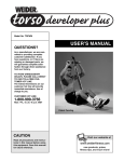
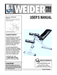
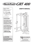
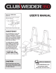
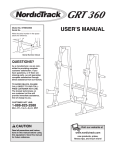
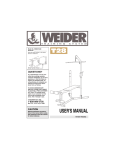
How to Order Replacement Parts
¨
To order replacement parts, contact the ICON Health & Fitness Ltd. office, or write:
ICON Health & Fitness, Ltd.
Greenwich House
223 North Street
Sheepscar
Leeds LS7 2AA
West Yorkshire
Class HC Fitness Product
Model No. WEEVBE70300
Serial No.
Tel: Country Code:
0345-089009
Write the serial number in the
space above for reference.
USERÕS MANUAL
Fax: 0113-2411120
When ordering parts, please be prepared to give the following information:
¥ The MODEL NUMBER OF THE PRODUCT (WEEVBE70300)
¥ The NAME OF THE PRODUCT (WEIDER¨ PRO125)
¥ The SERIAL NUMBER OF THE PRODUCT (see the front cover of this manual)
¥ The KEY NUMBER OF THE PART(S) (see the PART LIST and the EXPLODED DRAWING attached in the centre of this manual)
¥ The DESCRIPTION OF THE PART(S) (see the PART LIST and the EXPLODED DRAWING attached in the centre of this manual).
Serial Number Decal
QUESTIONS?
As a manufacturer, we are
committed to providing
complete customer satisfaction.
If you have questions, or if
there are missing parts, we will
guarantee complete satisfaction
through our Customer Service
Department.
0345-089009
Please CALL:
Or WRITE:
ICON Health & Fitness Ltd.
Greenwich House
223 North Street
Sheepscar
Leeds LS7 2AA
West Yorkshire
CAUTION
Read all precautions and instructions in this manual before
using this equipment. Save this
manual for future reference.
Part No. 169596 R0900A
Printed in China © 2000 ICON Health & Fitness, Inc.
Visit our website at
www.weiderfitness.com
new products, prizes,
fitness tips, and much more!
Table of Contents
Warning Decal Placement . . . . . . . . . . . . . . . . . . . . . . . . . . . . . . . . . . . . . . . . . . . . . . . . . . . . . . . . . . . . . . . . 2
Important Precautions . . . . . . . . . . . . . . . . . . . . . . . . . . . . . . . . . . . . . . . . . . . . . . . . . . . . . . . . . . . . . . . . . . . 3
Before You Begin . . . . . . . . . . . . . . . . . . . . . . . . . . . . . . . . . . . . . . . . . . . . . . . . . . . . . . . . . . . . . . . . . . . . . . 4
Assembly . . . . . . . . . . . . . . . . . . . . . . . . . . . . . . . . . . . . . . . . . . . . . . . . . . . . . . . . . . . . . . . . . . . . . . . . . . . . 5
Adjusting the Weight Bench . . . . . . . . . . . . . . . . . . . . . . . . . . . . . . . . . . . . . . . . . . . . . . . . . . . . . . . . . . . . . . 9
Exercise Guidelines . . . . . . . . . . . . . . . . . . . . . . . . . . . . . . . . . . . . . . . . . . . . . . . . . . . . . . . . . . . . . . . . . . . 10
How to Order Replacement Parts . . . . . . . . . . . . . . . . . . . . . . . . . . . . . . . . . . . . . . . . . . . . . . . . . . Back Cover
Note: A Part List, an Exploded Drawing, and a Part Identification Chart are attached in the centre of this manual.
Remove these pages before beginning assembly.
Rest for a short period of time after each set. The
ideal resting periods are:
¥ Rest three minutes after each set for a muscle building workout
¥ Rest one minute after each set for a toning workout
¥ Rest 30 seconds after each set for a weight loss
workout.
Plan to spend the first couple of weeks familiarising
yourself with the equipment and learning the proper
form for each exercise.
slowly as you stretch and do not bounce. Ease into
each stretch gradually and go only as far as you can
without strain. Stretching at the end of each workout
is very effective for increasing flexibility.
STAYING MOTIVATED
For motivation, keep a record of each workout. List
the date, the exercises performed, the weight plus the
numbers of sets and repetitions completed. Record
your weight and key body measurements at the end
of every month. Remember, the key to achieving the
greatest results is to make exercise a regular and
enjoyable part of your everyday life.
COOLING DOWN
End each workout with 5 to 10 minutes of stretching.
Include stretches for both your arms and legs. Move
SUGGESTED EXERCISES
These pictures show a variety of exercises that can be performed with your weight bench. Note: Your bench
may differ in appearance from the benches shown in the photos.
Warning Decal Placement
The decals shown at the right
have been placed on the
weight bench. If either of the
decals is missing or illegible,
please call our Customer
Service Department toll-free
at 0345-089009 to order a free
replacement decal. Apply the
replacement decal in the location shown.
Roman Chair
Alternate French Curl
Flyes
Incline Sit-up
Leg Raise
Bench Press
WEIDER is a registered trademark of ICON Health & Fitness, Inc.
2
11
Exercise Guidelines
Important Precautions
THE FOUR BASIC TYPES OF WORKOUTS
PERSONALIZING YOUR EXERCISE PROGRAM
Muscle Building
The only way to increase the size and strength of
your muscles is to push them close to their maximum
capacity. When you progressively increase the intensity of your exercise, your muscles will continually
adapt and grow. You can tailor the individual exercise
to the proper intensity level in two ways:
¥ by changing the amount of weight used
¥ by changing the number of repetitions or sets performed (A ÒrepetitionÓ is one complete cycle of an
exercise, such as one sit-up. A ÒsetÓ is a series of
repetitions).
Specifying the exact length of time for each workout,
as well as the number of repetitions or sets for each
exercise, is a highly individual matter. It is very important to avoid overdoing it during the first few months
of your exercise program. You should progress at
your own pace and be sensitive to your bodyÕs signals. If you experience pain or dizziness at any time
while exercising, stop immediately and begin cooling
down. Find out what is wrong before continuing.
Remember that adequate rest and a proper diet are
important factors in any exercise program.
WARMING UP
The proper amount of weight for each exercise obviously depends upon the individual user. You must
gauge your limits and select the amount of weight that
is right for you. Begin with 3 sets of 8 repetitions for
each exercise you perform. Rest for 3 minutes after
each set. When you can complete 3 sets of 12 repetitions without difficulty, increase the amount of weight.
Begin each workout with 5 to 10 minutes of stretching
and light exercise to warm up. Warming up prepares
your body for more strenuous exercise by increasing
circulation, raising your body temperature and delivering more oxygen to your muscles.
WORKING OUT
Toning
You can tone your muscles by pushing them to a
moderate percentage of their capacity. Select a moderate amount of weight and increase the number of
repetitions in each set. Complete as many sets of 15
to 20 repetitions as possible without discomfort. Rest
for 1 minute after each set. Work your muscles by
completing more sets rather than by using high
amounts of weight.
Each workout should include 6 to 10 different exercises. Select exercises for every major muscle group
with emphasis on the areas that you want to develop
the most. To give balance and variety to your workouts, vary the exercises from session to session.
Weight Loss
To lose weight, use a low amount of weight and
increase the number of repetitions in each set.
Exercise for 20 to 30 minutes, resting for a maximum
of 30 seconds between sets.
1. Read all instructions in this manual before
using the weight bench.
11. The weight bench is intended for home use
only. Do not use the weight bench in any
commercial, rental or institutional setting.
2. Use the weight bench only as described in
this manual.
12. Always make sure that the locking pins are
fully inserted and in the proper position for
the exercise you are performing.
3. It is the responsibility of the owner to ensure
that all users of the weight bench are adequately informed of all precautions.
13. When the seat is tilted to the upright position,
always insert the locking pin into the hole in
the seat frame as shown below. Do not insert
the locking pin into the welded tube.
4. Use the weight bench only on a level surface.
Cover the floor beneath the weight bench to
protect the floor.
14. When the seat is in the lower position, insert
the locking pin into the welded tube to prevent the seat from pivoting during exercise.
5. Inspect and tighten all parts each time you
use the weight bench. Replace any worn
parts immediately.
Seat
Frame
6. Keep children under the age of 12 and pets
away from the weight bench at all times.
7. Always wear athletic shoes for foot protection while exercising.
Welded
Tube
8. Keep hands and feet away from moving parts.
Schedule your workouts for the time of day when your
energy level is the highest. Each workout should be
followed by at least one day of rest. Once you find the
schedule that is right for you, stick with it.
9. The weight bench is designed to support a
maximum of 165 kg, including the user and
dumbbells.
EXERCISE FORM
10. If you feel pain or dizziness at any time while
exercising, stop immediately and begin cooling down.
You will gain the greatest benefits from exercising by
maintaining proper form. This requires moving
through the full range of motion for each exercise and
moving only the appropriate parts of the body.
Exercising in an uncontrolled manner will leave you
feeling exhausted.
Cross Training
Many people desire a complete and well-balanced fitness program, and cross training is a very efficient
way to accomplish this. One example of a balanced
program is:
¥ Plan weight training workouts on Monday,
Wednesday and Friday.
¥ Plan 20 to 30 minutes of aerobic exercise, such as
cycling or swimming on Tuesday and Thursday.
¥ Rest from both weight training and aerobic exercise
for at least one full day each week to give your body
time to regenerate.
The combination of weight training and aerobic exercise will reshape and strengthen your body plus
develop your heart and lungs.
WARNING:
To reduce the risk of serious injury, read the following important precautions
before using the weight bench.
WARNING:
Before beginning this or any exercise program, consult your physician. This
is especially important for persons over the age of 35 or persons with pre-existing health problems.
Read all instructions before using. ICON assumes no responsibility for personal injury or property
damage sustained by or through the use of this product.
The repetitions in each set should be performed
smoothly and without pausing. The exertion stage of
each repetition should last about half as long as the
return stage. Proper breathing is important. Exhale
during the exertion stage of each repetition and inhale
during the return stroke. Never hold your breath!
10
Locking
Pin
3
Adjusting the Weight Bench
Before You Begin
Thank you for selecting the versatile WEIDER¨ PRO
125 weight bench. The WEIDER¨ PRO 125 is
designed to help you develop every major muscle
group of the body. Whether your goal is a shapely figure, dramatic muscle size and strength or a healthier
cardiovascular system, the PRO 125 weight bench will
help you achieve the specific results you want.
Service Department 0345-089009. To help us assist
you, please note the product model number and serial
number before calling. The model number is WEEVBE70300. The serial number can be found on a
decal attached to the weight bench (see the front
cover of this manual).
This section explains how to adjust the weight bench. See the EXERCISE GUIDELINES on page 10 for important information on how to get the most benefit from your exercise program.
Inspect and tighten all parts each time you use the weight bench. Replace any worn parts immediately. The
weight bench can be cleaned with a damp cloth and a mild, non-abrasive detergent. Do not use solvents.
ADJUSTING THE BACKREST
Before reading further, please review the drawing
below and familiarise yourself with the parts that are
labelled.
For your benefit, read this manual carefully before
using the WEIDER¨ PRO 125 weight bench. If you
have additional questions, please call our Customer
Backrest
Foam Pad
The Backrest (8) can be used in a level position, two
inclined positions, and a declined position. To adjust the
Backrest to a level position or an inclined position, first
remove the Locking Pin (16). Raise or lower the
Backrest and insert the Locking Pin through one of the
three lower sets of holes in the adjustment bracket and
through the welded tube in the Main Frame (1).
To use the Backrest (8) in a declined position, remove
the Locking Pin (16), lower the Backrest until it rests on
the Main Frame (1), and then re-insert the Locking Pin.
8
Adjustment
Bracket
1
16
Welded Tube
Seat Adjustment Bracket
ADJUSTING THE HEIGHT OF THE WEIGHT BENCH
Seat
Backrest
Adjustment
Bracket
Foam Pads
Leg
1
6
To adjust the height of the weight bench, loosen the
Adjustment Knob (23) and raise or lower the Main
Frame (1) to the desired height. Align the hole in the
Leg (6) with one of the holes in the Adjustment Leg (7).
Re-insert the Adjustment Knob and tighten it fully into
the welded nut.
23
Welded
Nut
Main Frame
7
Adjustment Knob
Adjustment Leg
SETTING UP THE WEIGHT BENCH FOR ROMAN
CHAIR EXERCISES
Stabiliser
To use the weight bench for roman chair exercises, first
raise the Seat Frame (5) to the upright position. Insert the
Locking Pin/w Ring (30) through the indicated hole in the
adjustment bracket and the hole in the Seat Frame.
Adjust the height of the weight bench as described above
so the Seat (9) is in a comfortable position.
Note: When the Seat (9) is in the lower position, insert
the Locking Pin/w Ring (30) through the welded tube to
prevent the Seat from pivoting during exercise.
9
5
Welded
Tube
30
WARNING:
When the Seat (9) is tilted to the upright position, always insert the
Locking Pin w/Ring (30) into the hole in the Seat
Frame (5) as shown. Do not insert the Locking
Pin into the welded tube.
4
Adjustment
Bracket
9
9. Attach the Seat (9) to the brackets on the Seat
Frame (5) with four M6 x 16mm Screws (15).
Assembly
9
9
5
The following tools (not included) are required
for assembly:
Before beginning assembly, carefully read the
following information and instructions. If assistance is needed, call 0345-089009.
¥ Two (2) adjustable wrenches
¥ Assembly requires two people.
¥ One (1) rubber mallet
15
¥ Place all parts in a cleared area and remove the
packing materials. Do not dispose of the packing
materials until assembly is completed.
¥ One (1) standard screwdriver
¥ One (1) phillips screwdriver
15
¥ Tighten all parts as you assemble them, unless
instructed to do otherwise.
¥ Lubricant, such as grease or petroleum jelly,
and soapy water.
¥ To identify small parts, use the PART IDENTIFICATION CHART in the centre of this manual.
10. Press 19mm Round Inner Caps (13) into the ends
of the Long Pad Tube (12) and the Short Pad Tube
(31).
Assembly will be more convenient if you have a
socket set, a set of open-end or closed-end
wrenches, or a set of ratchet wrenches.
¥ As you assemble the weight bench, make sure all
parts are oriented as shown in the drawings.
10
11
3
Slide a Plastic Spacer (3) and a Foam Pad (11)
onto one end of the Long Pad Tube (12). Insert the
Long Pad Tube into the hole in the Seat Frame (5).
Slide a Plastic Spacer (3) and a Foam Pad (11)
onto the other end of the Long Pad Tube.
1. Before assembling this product, make sure that
you understand the information in the box
above.
12
13
3
13
5
3
31
Mount the Short Pad Tube (31) in the Leg (6) by
following the instructions above.
11
3
6
11. Make sure that all parts are tightened before
you use the weight bench. Cover the floor
beneath the weight bench to protect the floor.
1
Turn one of the Stabilisers (2) so the warning decal
is facing up as shown. Note that on one side of the
Stabiliser there is an indentation around each of the
two holes. Insert two M10 x 72mm Carriage Bolts
(21) through the holes in the Stabiliser so that the
bolt heads fit into the indentations.
1
18
10
Slide the bracket on the Main Frame (1) onto the
two M10 x 72mm Carriage Bolts (21) in the
Stabiliser (2). Make sure that the Main Frame is
turned as shown. Tighten an M10 Nylon Locknut
(18) onto each Carriage Bolt.
2
Decal
2. Insert two M10 x 70mm Bolts (19) through the holes
in the Support Plate (27) and then through the indicated holes in the Main Frame (1).
10
21
Press a 60mm Round Endcap (10) onto each end of
the Stabiliser (2).
2
19
27
Slide the bracket on the Leg (6) onto the two M10 x
70mm Bolts (19). Tighten two M10 Nylon Locknuts
(18) onto the Bolts.
Press a Square Bushing (22) onto the lower end of
the Leg (6). Press a 25mm Square Inner Cap (24)
into the tube on the Leg.
24
1
6
18
8
5
22
3. Locate the second Stabiliser (2) and note the indentations around the holes. Insert two M10 x 72mm
Carriage Bolts (21) through the holes in the
Stabiliser so that the bolt heads fit into the indentations.
6. Note that the bracket on the Backrest Frame (4)
has four sets of oval holes and one set of round
holes. Hold the 15mm x 10.5mm x 67mm Spacer
(28) between the round holes in the bracket. Insert
an M10 x 85mm Bolt (29) through the bracket and
the Spacer. Tighten an M10 Nylon Locknut (18)
onto the Bolt. Make sure that the Spacer is under
the Main Frame (1).
3
7
18
18
Slide the bracket on the Adjustment Leg (7) onto
the two M10 x 72mm Carriage Bolts (21) in the
Stabiliser (2). Tighten an M10 Nylon Locknut (18)
onto each Bolt.
10
Press a 60mm Round Endcap (10) onto each end
of the Stabiliser (2).
2
10
6
29
4
16
Round
Hole
Insert the Locking Pin (16) through one of the four
sets of oval holes in the bracket on the Backrest
Frame (4) and through the welded tube in the Main
Frame (1) (the welded tube is shown in drawing
5).
18
Oval
Adjustment
Holes
21
4. Slide the Adjustment Leg (7) up into the Leg (6).
Line up one of the holes in the Adjustment Leg with
the indicated hole in the Leg.
1
7. Attach the Backrest (8) to the brackets on the
Backrest Frame (4) with four M6 x 16mm Screws
(15).
4
7
8
6
Insert the Adjustment Knob (23) into the holes in
the Leg (6) and the Adjustment Leg (7). Fully tighten
the Adjustment Knob into the indicated welded nut.
28
Welded
Nut
1
Hole
7
23
4
15
15
5. Attach a 30mm x 25mm Bumper (26) to the indicated
hole in the Main Frame (1) with a Bumper Screw
(25).
8. Attach a 30mm x 25mm Bumper (26) to the indicated hole in the Main Frame (1) with a Bumper Screw
(25).
5
17
Hold the opposite end of the Backrest Frame (4)
inside the indicated bracket on the Main Frame (1).
Attach the Backrest Frame to the Main Frame with
an M10 x 80mm Bolt (17) and an M10 Nylon
Locknut (18). Do not overtighten the Nylon
Locknut; the Backrest Frame must pivot easily.
20
Press a 25mm x 50mm Inner Cap (14) into each
end of the Seat Frame (5).
Bracket
Press a 25mm x 50mm Inner Cap (14) into the indicated end of the Backrest Frame (4).
8
Note that the Seat Frame (5) has two welded
tubes. ÒTube AÓ passes through the Seat Frame
and Òtube BÓ is welded beneath the Seat Frame.
Do not confuse the two tubes in this step.
4
14
Welded
Tube A
14
Welded
Tube B
30
18
5
18
25
Welded
Tube
26
1
6
Align tube A in the Seat Frame (5) with the upper
hole in the indicated bracket on the Main Frame (1).
Attach the Seat Frame to the Main Frame with the
M10 x 95mm Bolt (20) and an M10 Nylon Locknut
(18). Do not overtighten the Nylon Locknut; the
Seat Frame must pivot easily.
Insert the Locking Pin w/Ring (30) through tube B
to prevent the Seat Frame (5) from pivoting.
7
Bracket
14
26
25
1
Part ListÑModel No. WEEVBE70300
Key No. Qty. Description
1
2
3
4
5
6
7
8
9
10
11
12
13
14
15
16
1
2
4
1
1
1
1
1
1
4
4
1
4
3
8
1
Main Frame
Stabiliser
Plastic Spacer
Backrest Frame
Seat Frame
Leg
Adjustment Leg
Backrest
Seat
60mm Round Endcap
Foam Pad
Long Pad Tube
19mm Round Inner Cap
25mm x 50mm Inner Cap
M6 x 16mm Screw
Locking Pin
R0900A
Part Identification ChartÑModel No. WEEVBE70300
R0900A
Key No. Qty. Description
17
18
19
20
21
22
23
24
25
26
27
28
29
30
31
#
1
9
2
1
4
1
1
1
2
2
1
1
1
1
1
1
M10 x 80mm Bolt
M10 Nylon Locknut
M10 x 70mm Bolt
M10 x 95mm Bolt
M10 x 72mm Carriage Bolt
Square Bushing
Adjustment Knob
25mm Square Inner Cap
Bumper Screw
30mm x 25mm Bumper
Support Plate
15mm x 10.5 x 67mm Spacer
M10 x 85mm Bolt
Locking Pin w/Ring
Short Pad Tube
UserÕs Manual
Note: Ò#Ó indicates a non-illustrated part. Specifications are subject to change without notice. See the back cover
of the userÕs manual for information about ordering replacement parts.
M10 x 70mm Bolt (19)Ð2
M10 Nylon Locknut (18)Ð9
M10 x 72mm Carriage Bolt (21)Ð4
Bumper Screw (25)Ð2
M10 x 80mm Bolt (17)Ð1
M10 x 85mm Bolt (29)Ð1
M10 x 95mm Bolt (20)Ð1
M6 x 16mm Screw (15)Ð8
Exploded DrawingÑModel No. WEEVBE70300
R0900A
11
3
11
13
9
12
14
3
13
13
20
3
31
8
30
19
13
5
27
29
18
15
17
14
25
15
24
16
26
18
18
4
3
15
18
28
14
15
25
1
26
11
6
18
23
22
7
18
18
10
18
18
10
10
2
21
2
10
21
11