1
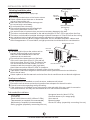
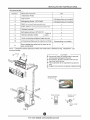
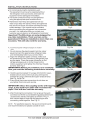
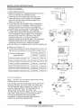
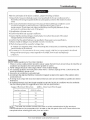
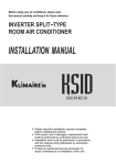
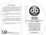
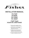
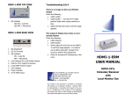
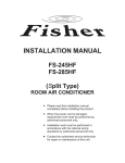
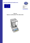
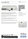
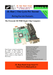
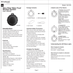
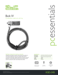
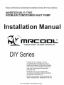
INSTALLATION INSTRUCTIONS
Selecting installation place
More than 15cm/5.9in
(to the ceiling)
Read completely, then follow step by step.
More than
More than
Indoor unit:
12cm/4.72in
12cm/4.72in
Do not expose the indoor unit to heat or steam.
Select a place where there are no obstacles
in front or around the unit.
Make sure that condensation drainage can
be conveniently routed away.
More than 2.3m/7.55ft
Do not install near a doorway.
(from the floor)
Ensure that the space on the left and right
Fig.1
of the unit is more than 12cm/4.72in.
Use a stud finder to locate studs to prevent unnecessary damage to the wall.
The indoor unit should be installed on the wall at a height of 2.3m/7.55ft or more from the floor.
The indoor unit should be installed allowing a minimum clearance of 15cm/5.9in from the ceiling.
Any variations in pipe length will/may require adjustment to refrigerant charge.
There should not be any direct sunlight. Otherwise, the sun will fade the plastic cabinet and
affect its appearance. If unavoidable, sunlight prevention should be taken into consideration.
More than30cm/11.81in
More than
Outdoor unit:
30cm/11.81in
If an awning is built over the outdoor unit to
prevent direct sunlight or rain exposure,
make sure that heat radiation from the
condenser is not restricted.
More than
Ensure that the clearance around the back
60cm/23.62in
of the unit is more than 30cm/11.81in and left
side is more than 30cm/11.81in. The front of the
More than 200cm/78.74in
unit should have more than 200cm/78.74in of
clearance and the connection side (right side)
Fig.2
should have more than 60cm/23.62in of clearance.
Do not place animals and plants in the path of the air inlet or outlet.
Take the air conditioner weight into account and select a place where noise and vibration
will not be an issue.
Select a place so that the warm air and noise from the air conditioner do not disturb neighbors.
Rooftop installation:
If the outdoor unit is installed on a roof structure, make sure unit is level.
Ensure the roof structure and anchoring method are adequate for the unit location.
Consult local codes regarding rooftop mounting.
If the outdoor unit is installed on roof structures or external walls, this may result in excessive
noise and vibration, and may also be classed as a non serviceable installation.
Tools needed for installation:
Level gauge
Screwdriver
Electric drill,Hole core drill (φ90mm/3.54in)
Thermometer (no required, but recommended)
Multimeter (no required, but recommended)
Saftey goggles (especially connecting line set)
Hexagonal wrench (4mm/0.157in)
Gas-leak detector (or a soapy spray)
User manual
Measuring tape
Gloves for saftey (especially connecting line set)
3
For more details visit www.MrCool.com
>12
TEST RUNNING
System
Power Supply
DIY-12
115/60/1
Eletrical Specifications
DIY-18
208-230/60/1
DIY-24
208-230/60/1
DIY-32
208-230/60/1
Min. Circuit Amps
20.0A
4.0A
15.0A
16.0A
Max Fuse
30.0A
20.0A
25.0A
25.0A
Terminal block of outdoor unit
L1 L2 S L1 L2
L1 L2 S L1 L2
To indoor unit
To power supply
To indoor unit
To power supply
Model A
1(L) 2(N) S L
To indoor unit
N
To power supply
Model B
Fig.27
Test running:
Perform test operation after completing gas leak check at the flare nut connections and
electrical safety check.
Check that all tubing and wiring have been properly connected.
Check that the gas and liquid side service valves are fully open.
1. Connect the power, press the ON/OFF button on the remote controller to turn the unit on.
2. Use the MODE button to select COOL, HEAT, AUTO and FAN to check if all the functions
works well.
3. When the ambient temperature is too low(lower than 63 °F), the unit cannot be controlled by
the remote controller to run at cooling mode, manual operation can be taken. Manual
operation is used when the remote controller is disabled or maintenance is necessary.
Hold the panel sides and lift the panel up to an angle until it remains fixed
with a clicking sound.
Press the Manual control button to select the AUTO or COOL, the unit will
operate under Forced AUTO or COOL mode(see User Manual for details).
4. The test operation should last 30 minutes.
Manual control
button
AUTO/COOL
Fig.28
14
13
For more details visit www.MrCool.com