1
INSTRUCTION MANUAL
MODEL4200
KEW4202
DIGITAL EARTH CLAMP TESTER
MODEL 4200/KEW 4202
KYORITSU ELECTRICAL INSTRUMENTS
WORKS,LTD.
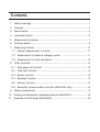
Contents
1. Safety warnings ............................................................................................. 1
2. Features .......................................................................................................... 3
3. Specification .................................................................................................. 4
4. Instrument layout ........................................................................................... 6
5. Measurement principle ................................................................................... 7
6. Getting started ................................................................................................. 9
7. Measuring method ...................................................................................... 10
7-1 Normal measurement of current .......................................................... 11
7-2 Measurement of balance leakage current ......................................... 11
7-3 Measurement of earth resistance ........................................................ 12
8. Other functions ............................................................................................ 13
8-1 Auto power-off function ........................................................................ 13
8-2 Data hold function ................................................................................. 13
8-3 Buzzer function ...................................................................................... 13
8-4 Backlight function ................................................................................... 13
8-5 Memory function ..................................................................................... 14
8-6 Bluetooth Communication Function (KEW4202 only) ....................... 15
9. Battery replacement .................................................................................... 17
10. Pairing with Bluetooth compatible devices (KEW4202) ......................... 18
11. Features of KEW Smart (KEW4202) ......................................................... 19
1. Safety Warnings
This instrument has been designed, manufactured and tested according to IEC
61010: Safety requirements for Electronic Measuring apparatus, and delivered
in the best condition after passing quality control tests. This instruction manual
contains warnings and safety procedures which have to be observed by the user to
ensure safe operation of the instrument and to maintain it in safe condition.
Therefore, read through these operating instructions before using the instrument.
# WARNING
Read through and understand the instructions contained in this manual
before using the instrument.
Keep the manual at hand to enable quick reference whenever necessary.
The instrument is to be used only in its intended applications.
Understand and follow all the safety instructions contained in the manual.
It is essential that the above instructions are adhered to. Failure to follow the
above instructions may cause injury, instrument damage and/or damage to
equipment under test.
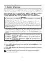
○ The symbol # indicated on the instrument means that the user must refer
to the related parts in the manual for safe operation of the instrument. It is
essential to read the instructions wherever the # symbol appears in the
manual.
: is reserved for conditions and actions that are likely to cause
serious or fatal injury.
# WARNING : is reserved for conditions and actions that can cause serious or
fatal injury.
# CAUTION : is reserved for conditions and actions that can cause injury or
instrument damage.
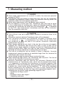
# DANGER
○ Following symbols are used on the instrument. Attention should be paid to each
symbol to ensure your safety.
This symbol indicates that the user must refer to the explanations in the
# instruction
manual.
This symbol indicates that the instrument is protected by double or reinforced
insulation.
This symbol indicates that this instrument can clamp on bare conductors.
∼This symbol indicates AC.
̶1̶
# DANGER
Never make measurement on a circuit in which the electrical potential exceeds
AC300V.
Do not make measurement when thunder is rumbling. Stop measurement and
take off the instrument from the object under test.
Do not attempt to make measurement in the presence of flammable gasses.
Otherwise, the use of the instrument may cause sparking, which can lead to an
explosion.
To avoid electrical shock by touching the equipment under test or its
surroundings, be sure to wear insulated protective gear.
Transformer jaws are made of metal and their tips are not completely insulated.
Be especially careful about the possible shorting where the equipment under test
has exposed metal parts.
Never attempt to use the instrument if its surface or your hand is wet.
Do not exceed the maximum allowable input of any measuring range.
Do not measure a current over 30A. Transformer jaws may heat to cause a fire or
deformation of molding parts, which will degrade insulation. When clamping the
conductors on which over 30A flowing and " " is displayed on the LCD, stop
measurement immediately and take off the instrument from the conductor under test.
Never open the Battery cover during a measurement.
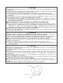
When the transformer jaws are worn to the wear line (see the figure below), stop
the use of the instrument.
# WARNING
Never attempt to make any measurement if any abnormal conditions, such as a
broken cover or exposed metal parts are present on the instrument.
Do not install substitute parts or make any modification to the instrument. Return
the instrument to your local KYORITSU distributor for repair or re-calibration.
Do not try to replace the batteries if the surface of the instrument is wet.
Ensure that the instrument is switched off when opening the Battery cover for
battery replacement.
Always be sure to keep your fingers and hands behind the Safety barrier.
(see the figure below) Otherwise, user may be exposed to the danger of
electrical shock.
# CAUTION
Press the Function button and confirm the appropriate function is selected before
starting a measurement.
Do not expose the instrument to direct sunlight, high temperatures and humidity
or dew.
Press the Power button and turn off the instrument after use. When the instrument
will not be in use for a long period, place it in storage after removing the
batteries.
Use a damp cloth with water or neutral detergent for cleaning the instrument. Do
not use abrasives or solvents.
Take sufficient care not to apply shock such as drop. Otherwise, precisely
adjusted Transformer jaws will be damaged.
Be careful not to pinch some foreign substances with the Transformer jaw tips.
Care should be taken not to pinch your fingers when opening or closing the
Jaws.
Pass your hand through the Strap band and use the instrument.
̶2̶
2. Features
This instrument is a digital clamp-on earth resistance tester, and it is used in multiearthed systems. Can measure the earth resistance by simply clamping around the
earthed wires.
This instrument also equips AC current function to measure current up to 30A
same as our traditional leakage clamp meters.
A single earthing cannot be measured. (only for multiple-earthing system)
Wide measuring range (Auto-ranging)
Earth/ground resistance Max. 1200Ω
AC current
Max. 30A
Min. resolution 0.01Ω
Min. resolution 0.1mA
Noise check function
A function to detect current, which effects on an earth resistance measurement
and display the NOISE symbol on the LCD.
True RMS
Accurate true RMS readings of AC current with distorted waveform.
Auto power-off function
A function to prevent the instrument from being left turned on and conserve
battery power.
Data hold function
A function to freeze the measured value on the display.
Buzzer function
A function to give audible warning to the user when the measurement result is
10Ω or less.
Backlight function
A function to facilitate working at dimly lit areas.
Memory function
A function to save and display the measurement result.
Designed to following safety standard.
IEC61010-1 (CAT.IV 300V Pollution degree 2), IEC61010-2-032
This instrument is protected by double or reinforced insulation .
● Bluetooth Communication Function (KEW4202 only)
Remote checking of measurements is possible without accessing KEW4202
unit by connecting KEW4202 and Android devices via Bluetooth.
̶3̶
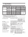
3. Specification
Measuring range and accuracy
Function
Range
20Ω
200Ω
Resolution
0.01Ω
0.1Ω
600Ω
1Ω
1200Ω
100mA
1000mA
10A
30A
10Ω
0.1mA
1mA
0.01A
0.1A
Earth resistance
(Auto-ranging)
AC current (ACA)
(50Hz/60Hz)
(Auto-ranging)
Measuring range
Accuracy
0.00 - 20.00Ω ±1%±5dgt
20.0 ‒ 200.0Ω ±3%±5dgt
200 - 399Ω ±6%±5dgt
400 - 599Ω ±10%±10dgt
600 - 1260Ω
0.0 - 100.0mA
100 - 1000mA ±2%±5dgt
1.00 - 10.00A (sine wave)
10.0 - 30.0A
* Crest factor ≦2.5 Accuracy at sine wave +1% (50Hz/60Hz, peak value shall not exceed 60A)
* In the following cases, zero will be displayed on the LCD.
- At 20Ω range of Earth resistance function: 0.04Ω or less
- At 100mA range of ACA function: 0.4mA or less
* A range shifts to upper range when the input exceeds 105% of the selected range, and shifts
to the lower range when the input falls under 80% of the range.
Operating system
Earth resistance function: Constant voltage injection,
Current detection,
(Frequency: Approx.2400Hz)
Dual Integration
AC current function:Successive Approximation(True-RMS)
Display
Liquid crystal display with a maximum count of 2099
Over-range indication
"OL" is displayed when input exceeds the upper limit
of the measuring range
Response time
Earth resistance function :Approx. 7 seconds
AC current function
:Approx. 2 seconds
Sample rate
Approx. once per second
Location for use
Altitude 2000m or less, Indoor/ outdoor use
IP protection degree
IP40
Temperature & humidity range 23℃ ±5℃ /Relative humidity 85% or less
(guaranteed accuracy) (no condensation)
Operating temperature & -10℃ to 40℃ /Relative humidity 85% or less
humidity range
(no condensation)
Storage temperature &
-20℃ to 60℃ /Relative humidity 85% or less
humidity range
(without batteries, no condensation)
Power source
DC6V: R6P (size AA manganese battery) x 4pcs, or
LR6 (size AA alkaline battery) x 4pcs
Current consumption
MODEL4200 : Approx. 50mA (max. 100mA)
KEW4202
: Approx. 90mA (max. 140mA)
Measurement time
MODEL4200 : Approx. 12 hours (when using R6P), or
24 hours (when using LR6)
KEW4202
: Approx. 5 hours (when using R6P), or
21 hours (when using LR6)
̶4̶
Auto power-off
Turns power off about 10 minutes after the last
button operation.
Applicable standards
IEC61010-1 (CAT. IV 300V Pollution degree2)
IEC61010-2-032
IEC61326-2-2 (EMC standard)
External communication Bluetooth Ver2.1+EDR Class2
method
Withstand voltage
AC5160Vrms/ 5 seconds
Between the Transformer jaws fitted parts and Case
enclosure (except for jaws)
Insulation resistance
50MΩ or more at 1000V
Between the Transformer jaws fitted parts and Case
enclosure (except for jaws)
Conductor size
Approx. 32mm in diameter max.
Dimension
246(L) x 120(W) x 54(D)mm
Weight
Approx. 780g (including batteries)
Accessories
Battery R6P: 4pcs (MODEL4200)
LR6: 4pcs (KEW4202)
Instruction manual
: 1pce
Resistor for operation check : 1pce
(MODEL8304)
Hard case MODEL9166
: 1pce (MODEL4200)
MODEL9167
: 1pce (KEW4202)
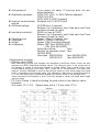
<Supplemental remarks>
○ Effective value (RMS)
Most alternating currents and voltages are expressed in effective values, which are also
referred to as RMS (Root-Mean-Square) values. The effective value is the square root of
the average of square of alternating current or voltage values. Many clamp meters using
a conventional rectifying circuit have "RMS" scales for AC measurement. The scales are,
however, actually calibrated in terms of the effective value of a sine wave though the clamp
meter is responding to the average value. The calibration is done with a conversion factor of
1.111 for sine wave, which is found by dividing the effective value by the average value.
These instruments are therefore in error if the input voltage or current has some other shape
than sine wave.
○ CF (Crest Factor) is found by dividing the peak value by the effective value.
Examples:
Sine wave: CF=1.414 Square wave with a 1: 9 duty ratio: CF=3
̶5̶
4. Instrument layout
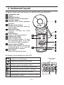
Name of each parts and buttons (for MODEL4200 and KEW4202)
1 Transformer jaw
2 Trigger
3 Backlight button
Switches on/off the backlight.
4 Function button
Switches ACA/ Earth resistance
functions.
5 Memory mode button
C heck the measured value by
Data number.
6 Data hold button
F reezes/ releases the fixed
readings.
7 Power button
Turns on/off the instrument.
8 Display unit (LCD)
9 Cursor button (UP)
S elects data number; to save
the measured value, or to view
the measured data in memory.
10 Cursor button (DOWN)
Selects data number; to save the
measured value, or to view the
measured data in memory.
11 Save button
Saves the measured value.
1
2
3
6
4
7
8
9
11
5
10
Symbols to be displayed on the LCD
Displayed when saving the measured value or when
instrument is in memory mode.
Data number
1 to 100
Displayed when batteries are exhausted.
Displayed at Earth resistance function when
Transformer jaws are not properly closed.
Displayed at Earth resistance function when current or
noise that affects on the measured value presents.
Displayed when data hold function is activated.
Displayed when ACA function is selected.
Displayed when instrument is in continuity mode at
Earth resistance function.
̶6̶
Measured value
Unit
5. Measurement principle
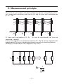
This instrument can measure the earth resistance to earth in multi-earthed system.
Let's regard earth resistance under test as Rx, and the other earth resistances as
R1, R2, …Rn.
Of these earth resistances, R1, R2, …Rn can be considered that they are
connected in parallel.
And can be regarded as a combined resistance Rs. The Rs can be regarded small
enough against Rx since a combined resistance consists of several resistances.
Following is an equivalent circuit diagram of this circuit.
̶7̶
By applying the Voltage (V) to the circuit from the Transformer jaw (CT1), current I
is (shall be flowed) flowed corresponding to the earth resistance. R can be put out
by the calculation after detecting the current with the other Transformer jaw (CT2).
In this case, R displayed in this instrument can be regarded as Rx because Rs can
be regarded small enough against Rx.
# CAUTION
This instrument is not supporting the measurement for the locations with
following earth systems.
Single-earth that is not connected to other earths. (Lightning rod, etc.)
Earth on which a current over 2A is measured at AC current function of this
instrument.
Earth with a larger earth resistance than an earth resistance of testing.
Earth with earth resistance over 1200Ω.
Precision measurement shall be performed with our Earth resistance tester:
M-4102A or M-4105A for the measurement of single-earthed wire.
M-4102A
̶8̶
6. Getting started
# CAUTION
This instrument performs self-calibration for about 3 seconds when it is turned
" is displayed on the LCD.) Do not clamp onto any conductor or
on. ("
open the jaws in this period. Otherwise, inaccurate measurement may occur.
(1) Check the battery voltage
When nothing is displayed on the LCD, press the power button
and turn
on the instrument. Battery voltage is enough when indication is clear and the
"
" symbol is not displayed on the LCD after turning on the instrument.
Follow the procedure described in“9. Battery replacement”and replace the
batteries with new ones when any of following symptoms is noted. Otherwise,
accurate measurement and proper saving cannot be ensured.
* "
" symbol is being displayed.
* indications are faint and difficult to read.
* nothing is displayed on the LCD.
(2) Verify the correct measurement of earth resistance
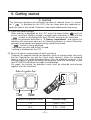
Clamp-on the supplied resistor for operation check as shown below, and verify
that the Transformer jaw and the circuit works correctly. When the indicated
value is within the range described below, they are operating correctly. If the
indicated value is greatly exceeding the accuracy, send the instrument to your
local KYORITSU distributor for repair or recalibration.
For repair, the resistor for operation check shall be attached and returned
together with the instrument.
Resistor for operation check
Allowable range
1Ω
0.93 ∼ 1.07
10 Ω
9.75 ∼ 10.25
̶9̶
7. Measuring method
# DANGER
Never make measurement on a circuit in which the electrical potential
exceeds AC300V.
Transformer jaws are made of metal and their tips are not completely
insulated. Be especially careful about the possible shorting where the
equipment under test has exposed metal parts.
Never make measurement with the Battery cover removed.
Do not measure a current over 30A. Transformer jaws may heat to cause
a fire or deformation of molding parts, which will degrade insulation. When
" is displayed
clamping the conductors on which over 30A flowing and "
on the LCD, stop measurement immediately and take off the instrument
from the conductor under test.
# CAUTION
Take sufficient care not to apply shock, vibration or excessive force to the
jaw tips.
Otherwise, precisely adjusted Transformer jaws will be damaged.
This instrument performs self-calibration for about 3 seconds when
" is displayed on the LCD.) Do not clamp onto
it is turned on. ("
any conductor or open the jaws in this period. Otherwise, inaccurate
measurement may occur.
When foreign substances are stuck in the jaw tips or they are not properly
engaged, the Transformer jaws do not fully close. In such a case, do not
release the jaw trigger abruptly or attempt to close the Transformer jaws by
applying external force. Make sure that the jaws close by themselves after
removing the foreign substance or making them free to move.
The size of a conductor can be tested is 30mm in diameter. Accurate
measurement cannot be made on a conductor larger than this, because the
Transformer jaws cannot fully close.
Never attempt to apply excessive force to close the jaws.
When measuring large current, the Transformer jaws may buzz. This has no
effect on the instrument's performance or safety.
Sensitive Transformer jaws are used for this instrument. Because of the
characteristics of Transformer jaws, which can be opened and closed,
it is impossible to eliminate the interference of external magnetic field
completely. If there are something, which generating large magnetic field, at
a nearby site, current value can be displayed (“0”may not be displayed)
before clamping on the conductor. For such a case, please use the
instrument at a location far from the thing, which generating magnetic field.
Following are the typical things generating magnetic field.
* Conductor fed large current
* Motor
* Equipment which has magnet
* Integrating wattmeter
̶ 10 ̶
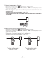
7-1 Normal measurement of current
and select the ACA function.
* Press the Function button
* Confirm the displayed unit is " mA ", and the " MEM " is not displayed at the
upper left on the LCD.
* Press the trigger to open the Transformer jaws, and close them over one
conductor only.
* Measured current value is displayed on the LCD.
(Earth leakage current that flows through an earthed wire can be measured by
this method.)
7-2 Measurement of balance leakage current
and select the ACA function.
* Press the Function button
* Confirm the displayed unit is " mA ", and the " MEM " is not displayed at the
upper left on the LCD.
* Clamp onto all conductors except for the earthed wire.
* Measured current value is displayed on the LCD.
Load
Load
Single-phase 2-wire system
Three-phase 3-wire system
In 3-wire system with neutral,
clamp onto all 3 wires.
In 4-wire system with neutral,
clamp onto all 4 wires.
̶ 11 ̶
7-3 Measurement of earth resistance
# CAUTION
Follow the procedure described in "7-1 Normal measurement of
current" and measure the current flowing on the earthed wire prior to the
measurement of earth resistance.
In case that the "
" symbol is displayed at the upper right of the
LCD, it means that a great error would be included in the measured result.
To avoid such inaccurate measurement, reduce the current flowing on the
earthed wire by turning off the device from which current is applied to the
earthed line under test.
Measurement cannot be made for the earth without multi-earthing system or
when the earth resistance under test is smaller than the other earth resistances.
To avoid inaccurate reading may be taken, never make a measurement for
the same earth system with multiple units of this instruments.
The "
" symbol may be displayed during a measurement of earth
resistance. It indicates that the jaws of the instrument are not properly
closed. Measurement is being stopped while this symbol is displayed on the
LCD. Close the Transformer jaws properly to re-start the measurement.
Response time at Earth resistance function is about 7 seconds. It takes
awhile until the readings become stable.
Measurement procedure
* Press the Function button
and select the Earth resistance function.
* Confirm the displayed unit is " Ω ", and " MEM " is not displayed at the upper
left on the LCD.
* Press the trigger to open the Transformer jaws, and close them over the
earthed wire under test.
* Measured resistance value is displayed on the LCD.
<Noise check function>
At the Earth resistance function, the "
" symbol is displayed on the LCD in
the following cases which may effect on a measurement.
* The current flowing on the earthed wire is exceeding the following value.
Range of Earth resistance function
Allowable current value
20Ω
2A or less
200Ω/600Ω/1200Ω
400mA or less
* The current flowing on the earthed wire includes a harmonic wave which
effects on the measurement.
<Jaws check function>
The "
" symbol is displayed when the Transformer jaws of the instrument are
not properly closed.
Measurement will be stopped when this symbol appears on the LCD.
̶ 12 ̶
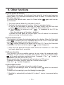
8. Other functions
8-1 Auto power-off function
This function is to prevent the instrument from being left turned on and conserve
battery power. The instrument automatically turns off about 10 minutes after the
last button operation.
To return to the normal mode, press the Power button
again and turns on
the instrument.
◇ The buzzer sounds before the instrument turns off.
◇ To disable the auto power-off function, follow the procedure below.
(1) Turn on the instrument by pressing the Power button with the Data hold
pressed down. Then release the Power button only.
button
(2) The instrument is turned on, and "
" is displayed on the LCD for
about 1 second.
Now, the auto power-off function is disabled.
To enable the auto power-off function again, turn off and on the instrument
without pressing the Data hold button.
8-2 Data hold function
This function is to freeze the indicated value on the display. When the Data hold
button
is pressed once, the indicated value on the LCD is fixed and does
not change even though current under test varies.
The "
" symbol is shown at the upper right on the LCD. To exit the Data hold
mode, press the Data hold button again. ("
" symbol disappears.)
◇ When the Auto power-off function works while the instrument is in the Data
hold mode, data hold is cancelled.
8-3 Buzzer function
This function is to give audible warning to user when the measured earth
resistance is 10Ω or less. To enable this function, press the Function button
at the earth resistance function at least 2 seconds. ( The "
" symbol is
displayed at the lower left on the LCD.)
Buzzer sounds when the measured earth resistance is 10Ω or less.
To disable the buzzer function, press the Function button again.
(Then, the "
" symbol disappears.)
8-4 Backlight function
This function is to view the test results in dimly lit areas.
To switch on the backlight, press the Backlight button
while the instrument
turned on.
To switch off the backlight, press the Backlight button again.
◇ Backlight is automatically switched off in about 1 minute to conserve battery
power.
̶ 13 ̶
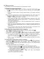
8-5 Memory function
This function is to save and display the measurement results.
Saving the measurement results
(1) Select any data number (from 1 to 100) by using the Cursor button
or
at ACA or Earth resistance function, and save the measurement
results.
◇ When the Cursor button is being pressed down, the number switches
quickly.
(2) To save the measurement result being displayed on the LCD, press the
Save button
. Then the result is saved to the selected data number.
(" MEM " is displayed for about 1 second.)
◇ After saving the data, data number automatically switches to the next
available data number (present data number +1) and the next measured
value can be saved to it.
(The data number returns to 1 after the measurement result is saved to
the data number 100.)
◇ When the new measurement result is saved to the data number on
which the previous measurement result is saved, previous data will be
overwritten.
◇ When saving a data while the data hold function is activated, the
readings which is being held on the LCD will be saved.
Recalling the measurement results in memory
To activate the memory function, press the Memory mode button
.
Then " MEM " is displayed on the LCD.
Pressing the Cursor button
or
changes the data number displayed
on the LCD, and the measurement result in memory is displayed accordingly.
◇ To disable the memory mode, press the Memory mode button again or
press the Function button
. (Then " MEM " symbol disappears.)
◇ Bars "
" are displayed for the Data number that does not contain
any test result.
Clearing the measurement results in memory
To clear the measurement result, press the Save button
with the Memory
pressed down. The message "
" is displayed on the
mode button
LCD for about 2 seconds and the measurement result on the selected data
number is cleared.
(Then the indication on the LCD becomes "
".)
◇ Follow the procedure below to delete the all measurement results.
(1) Press the Power button
, while the instrument is off, while the
Memory mode button and the Save button are being pressed down.
Then release the Power button only.
(2) Instrument is turned on; " MEM ", "
" and "
" are displayed
on the LCD for about 2 sec..
Now all the stored data are deleted.
̶ 14 ̶
8-6 Bluetooth Communication Function (KEW4202 only)
KEW4202 can perform data communication between Android devices via
Bluetooth communication.
Notes on using Bluetooth function:
This function is not available on MODEL4200 but available on KEW4202.
Before starting to use this function, download the special application“KEW
Smart”from the Internet site.
Some of the functions are available only while connected to the Internet. For
further details, please refer to“11. KEW Smart Functions”or“Help”for“KEW
Smart”.
# WARNING
Radio waves at Bluetooth communication may affect the operations of medical
electronic devices.
Special care should be taken when using Bluetooth connection in the areas
where such devices are present.
Cautions:
The maximum Bluetooth communication distance is approx. 10m. However,
it may be shortened if there are obstacles, such as walls, doors or people, or
depending on the radio wave condition or environment of usage.
Using KEW4202 or Android devices near wireless LAN devices (IEEE802.11.
b/g) may cause the radio interference, lowering of communication speed,
resulting in significant time lag in the display update rate between KEW4202
and Android device. In this case, keep KEW4202 and the Android device away
from the wireless LAN devices or turn off the wireless LAN devices, or shorten
the distance between KEW4202 and Android device.
It may be difficult to establish communication connection if either KEW4202
or Android device is in a metal box. In such cases, change the measurement
location or remove the metal obstacle between KEW4202 and Android device.
If any leaking of data or information occurs while making a communication
using Bluetooth function, we assume no responsibility for any released content.
Communication with KEW4202 may not be established even if using Android
device on which our special application operates. In that case, use the other
Android devices and check for connection.
If you cannot confirm the connection, there may be a problem with KEW4202
unit. Please contact your local KYORITSU distributor.
* The Bluetooth word mark and logos are owned by Bluetooth SIG, Inc. and any
use of such marks by Kyoritsu is licensed.
* Android and Google Map are the trademark or registered trade mark of Google
Inc..
* In this manual, the“TM”or“ ® ”mark is not specified.
̶ 15 ̶
Set-up:
First, set a Bluetooth connection (pairing) from an Android device. For further
details, please refer to the instruction manual for the Android device,“Help”for
“KEW Smart”or“10. Pairing with Bluetooth compatible devices”.
Communication with Android devices:
Measurement results of KEW4202 can be displayed on Android devices via
Bluetooth communication by using the special application“KEW Smart”.
Remote checking of measurements is possible without accessing KEW4202.
(1) Communication method
Power on KEW4202, select a measurement function, and then clamp onto
the object to be measured.
Activate“KEW Smart”on the Android device and select the device to
connect from the menu. Touch the“Start measurement”button on the
screen after the connection has been established. Then the measured
results will automatically be displayed on the Android device.
(2) Disconnection and Stop measurement
Touch the “Disconnect” button on the screen to disconnect the
communication. Touch the“Connect”button to reconnect.
Touch the“Stop measurement”button on the screen to stop measurement.
In this case, connection with KEW4202 will not be disconnected.
For various useful functions of“KEW Smart”, please refer to“11. KEW Smart
.
Functions”or“Help”for“KEW Smart”
̶ 16 ̶
9. Battery replacement
# WARNING
In order to avoid possible shock hazard, take off the instrument from the
conductor under test and turn off the instrument before trying to replace the
batteries.
# CAUTION
Do not mix new and old batteries. Never use the different kinds of batteries
at the same time.
Install batteries in correct polarity as marked inside.
When the battery voltage warning symbol "
" is displayed on the upper
"
left of the LCD, replace the batteries. Note that the display blanks and "
symbol is not displayed if the batteries are completely exhausted.
(1) Stop measurement when the warning symbol appears, and um-clamp from
the object under test.
(2) Ensure that the instrument is powered off.
(3) Loosen the Battery cover-fixing screw on the back of the instrument.
Then remove the Battery cover.
(4) Install new batteries (LR6 or R6P: 4pcs) in correct polarity as marked inside.
(5) Put the Battery cover in place and tighten the screw.
̶ 17 ̶
10. Pairing with Bluetooth compatible devices (KEW4202)
It is necessary to perform the pairing procedure to connect KEW4202 and Android
devices via Bluetooth communication.
If the“
“ symbol is displayed on the LCD of KEW4202, replace the
batteries with new ones before performing the pairing procedure.
(1) Power on KEW4202.
(2) Power on the Android device, and find the Setting menu. Look for the
Bluetooth setting in the Wireless Setting menu.
(3) On the Android device, choose Search for Bluetooth Devices. The model
s
name“KEW4202-XXXXXXX”will be displayed on the screen. The“X”
behind the model name is the serial no of the unit.
(4) Select and pair the device.
If the pairing setting fails, please check the following points.
- Distance between KEW4202 and the Android device
Move them closer, and perform the pairing procedure again.
- Bluetooth function on Android device
Turn on the Bluetooth function on the Android device and try again.
Depending on your network connection, it may take awhile to complete the pairing
procedure.
̶ 18 ̶
11. Features of KEW Smart (KEW4202)
Remote checking of measurements is possible without accessing KEW4202 using
.
the special Android application“KEW Smart”
The application“KEW Smart”is available on download site for free. (An Internet
access is required.)
Please note that communication charge is incurred separately for downloading
applications and using special features of them. For your information,“KEW
Smart”is provided on-line only.
Features of KEW Smart:
Remote checking of measurement is possible (earth/ground resistance and
AC current values)
Data hold function (on Android devices)
Save/ display measurement results
Measured results can be saved with comments. (max. 32 characters)
Save data includes measurement and GPS location while GPS feature has
been turned on.
Comparator function (earth/ground resistance value)
Informs when the measured value is lower or higher than the preset value.
Memory download function
Downloads the saved data from KEW4202 by pressing the Memory mode
Switch“
”on KEW4202. This function can be used while the instrument
is not performing measurements.
Features available using Internet connection:
E-mail
Measured data can be sent by E-mail while the connection to KEW4202 is
turned off.
Check on map
Measured locations can be checked on the Google Map if the saved data
includes GPS location.
On the Android device,“OPEN”or“NOISE”warning will be displayed in
conjunction with KEW4202.
.
For further details, please see“Help”for“KEW Smart”
Cautions:
Battery level of KEW4202 is not shown on Android devices. Ensure that the
battery level of KEW4202 is sufficient before starting to perform
measurements using these features. Replace batteries with new ones if
necessary.
Remote control, such as switching functions or activating data hold, of
KEW4202 from Android devices is not possible.
̶ 19 ̶
MEMO
̶ 20 ̶
MEMO
̶ 21 ̶
DISTRIBUTOR
Kyoritsu reserves the rights to change specifications or designs
described in this manual without notice and without obligations.
4-12
92-2088