1
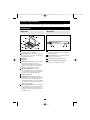
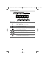
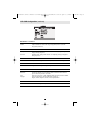
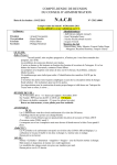
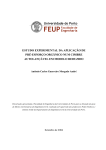
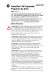
200708132 Owner’s Manual 93-2682 B021-000-19 Rackmount Console.qxd
Y
ce
NT ON: chanuct—
A
I
a d
RR RATay fore pro nty
A
t
i
d
T
W IS to p L warra
G line rip m/
RE er on REE Tlite.co
9/7/2007
Owner’s Manual
t
F pp
i
gis a
re win w.tr
to ww
1U Rackmount Console
with 19” Display
(for KVM Switch or Server)
Model #: B021-000-19
Tripp Lite World Headquarters
1111 West 35th Street, Chicago, IL 60609 USA
(773) 869-1234, www.tripplite.com
Note: Follow these instructions and operating procedures to ensure correct performance and to prevent damage
to this unit or to its connected devices.
Copyright © 2007 Tripp Lite. All rights reserved. All trademarks are the property of their respective owners.
The policy of Tripp Lite is one of continuous improvement. Specifications are subject to change without notice.
11:45 AM
Page 1
200708132 Owner’s Manual 93-2682 B021-000-19 Rackmount Console.qxd
9/7/2007
Package Content
• B021-000-19 1U Rackmount Console
• Mounting Hardware
• USB Cable Kit with PS/2 Adapter
• AC Power Cord
• Owner’s Manual
Table of Contents
Page
Overview
2
Features .......................................................................................................................................... 2
System Requirements ........................................................................................................................ 3
Introduction ...................................................................................................................................... 3
Front View .................................................................................................................................... 3
Rear View ...................................................................................................................................... 3
Installation ......................................................................................................................................4-7
LCD OSD (On-Screen Display) Configuration ........................................................................ 5-6
Rackmounting ................................................................................................................................ 7
Specifications ...................................................................................................................................... 8
Warranty ............................................................................................................................................ 8
Warranty Registration ........................................................................................................................8
Overview
The B021-000-19 1U Rackmount Console features an integrated LCD panel, full keyboard and touch pad
in a 1U rackmountable housing. These consoles are designed for use with a server or a KVM switch with
PS/2 or USB console port connectors.
Features Include
• Rackmount console (19” LCD display, keyboard, touch pad) in an integrated 1U
rackmountable housing
• Sleep mode when the monitor cover is closed
• Supports resolutions of up to 1024 x 768 pixels
• Rackmountable in 19" system rack (1U)
• Can be used with any device that includes PS/2 or USB console port connectors
2
11:45 AM
Page 2
200708132 Owner’s Manual 93-2682 B021-000-19 Rackmount Console.qxd
9/7/2007
System Requirements
• Supports most servers and KVM switches that have PS/2 or USB console port connectors
Introduction
Front View
Rear View
5
1
2
3
6
8
3
7
4
2
1
4
9
1 Hide-Away Handle: Pull to slide the module
1.
out; push to slide the module in.
2.
2 LCD Monitor: After sliding the module out,
flip up the cover to access the LCD monitor,
keyboard and touch pad.
3 Keyboard
3.
4.
4 Wrist Rests
5.
5 Slide Release: Mechanism to lock the drawer
closed when the console is not in use.
Prevents it from accidentally sliding open.
To slide the the console out, you must first
release it by moving this tab sideways.
6 Rackmounting Brackets: There are
6.
rackmounting brackets to secure the chassis
to a system rack located at each corner of the
unit. See p. 6 for rackmounting details.
7.
7 3-Button Touch Pad
8.
8 LCD Display Controls: The LCD OSD
controls located here control the position and
picture settings of the LCD display. See the
LCD OSD Configuration on p. 5-6 for details.
Also includes a power LED to indicate the
status of the LCD panel.
9.
9 Railway Release Tabs: When the drawer is
completely pulled out to the end, the railway
system will lock. Push these release tabs on
both sides to release the drawer so that it can
be pushed back in.
1.
1 Console Port Section: The cable kit to
connect the console to your server or KVM
switch plugs in here.
2 Power Socket: The power code plugs in here
2.
from the AC power source.
3 Power Switch: On/Off rocker switch.
3.
4 Auto-Detect (Internal): Automatically
3.
detects a PS/2 or USB connection.
3
11:45 AM
Page 3
200708132 Owner’s Manual 93-2682 B021-000-19 Rackmount Console.qxd
9/7/2007
Installation
2
1
3
Refer to the example installation diagram above as you perform the following steps:
1 Plug the cable kit (provided with this unit) into the port on the B021-000-19.
1.
2.
2 Plug the cable keyboard, monitor and mouse connectors on the other end of the USB cable kit into
their corresponding ports on the server or KVM switch. The cable kit includes a PS/2 adapter to
accommodate both USB and PS/2 connections.
3.
3 Plug the power cord into the B021-000-19’s power socket and into an AC power source.
4.
4 Power up your server or KVM installation.
5.
5 Turn on the power to the B021-000-19.
Note: The example diagram shows the B021-000-19 connecting to a B022-016 KVM switch. If you are
connecting to a different model, the console port connectors may be in a different location.
4
11:45 AM
Page 4
200708132 Owner’s Manual 93-2682 B021-000-19 Rackmount Console.qxd
9/7/2007
LCD OSD Configuration
Power LED
Power
Up
OSD Menu Controls
Down
Left
Menu/Selection
Right
Exit
Function
Power "ON/OFF" LED
Green = OSD menu "ON"
Orange = OSD menu "OFF" (power saving mode)
Press this to turn the monitor on or off.
Press this to bring up the configuration menu. Also, when scrolling through
the menu, press this to select an option.
Press these to scroll through the menu options.
Press these to increase or decrease the configuration settings.
Press this to return to the previous menu screen. Also, press this to perform
an auto adjust when not in the menu configuration.
5
11:45 AM
Page 5
200708132 Owner’s Manual 93-2682 B021-000-19 Rackmount Console.qxd
9/7/2007
LCD OSD Configuration (continue)
BRIGHTNESS / CONTRAST
Brightness:
Contrast:
Adjusts background black level of the screen image.
Adjusts the difference between the image background (black level) and the
foreground (white level).
AUTO ADJUST
Auto Adjust:
Auto Tune:
Fine-tunes the video signal to eliminate distortion. An "Adjusting" message is
displayed during the process.
Optimizes phase, clock, position and size. An "Adjusting" message is displayed
during the process.
PHASE/CLOCK
Phase / Clock:
Adjusts the vertical (phase) or horizontal (clock) size of the screen image.
H/V POSITION
H/V Position:
Aligns the screen image left or right and up or down.
MISC
Information:
OSD Timer:
Color:
Language:
Displays the current resolution, refresh rate and frequency information on the screen.
Sets the time duration in seconds that the OSD is visible after the last button is
pressed. The factory default is 10 seconds.
Selects the screen color - 5500K, 6500K & 9500K. The factory default is 9500K.
Selects the language in which the OSD menu is displayed English, Chinese, Japanese, German, French, Spanish, Italian.
RESET
Reset:
Restores the settings to factory defaults.
6
11:45 AM
Page 6
200708132 Owner’s Manual 93-2682 B021-000-19 Rackmount Console.qxd
Rackmounting
The B021-000-19 can be mounted in a 1U
system rack. For convenience and flexibility,
mounting hardware is provided with your
B021-000-19 package. The various options are
explained in the sections that follow.
Standard Rackmounting
The standard rackmounting brackets that come
with the B021-000-19 allow the unit to be
installed in standard 1U racks. If the unit can fit
into your rack “as is,” simply slide it into the rack
and screw it securely in place.
Optional Rackmounting
If there is not enough clearance for the unit to
slide into the rack when the rear flanges face
outward, the problem can be resolved with the
following procedure:
1. Locate the two included mounting brackets.
2. Turn the brackets so that the flanges face
inward; then screw them back into the chassis.
Note: Be sure to leave a 13mm gap between
the flange and the rear of the chassis in order
to have enough room to screw the tab to the
flange (referred to in step 4).
Steps 1-3
3. Slide the unit into the rack.
4. Screw the metal tabs to the rear flanges.
5. Secure the unit to the rack with the front
flanges and rear tabs.
Steps 4-5
The B021-000-19 can also be mounted in a 2post rack installation using the optional 2-Post
Rackmount Kit (model #: B019-000). The
mounting hardware allows for the consoles to be
opened with the drawer in any position. Heavyduty 14-gauge steel provides stability and
prevents console frame from twisting.
7
9/7/2007
11:45 AM
Page 7
200708132 Owner’s Manual 93-2682 B021-000-19 Rackmount Console.qxd
9/7/2007
Specifications
Function
Connectors
Console
Power
LEDs
Resolution
Environment
Housing
Weight
Dimensions (L x W x H)
Specification
1 x HD15 male
1 x AC Input socket (IEC-320-C14)
1 x Power (Green/Orange)
1024 x 768; DDC2B
Operating Temperature: 32°- 122° F
Storage Temperature: -4°- 140° F
Humidity: 0 - 80% RH Noncondensing
Metal
26.9 pounds
25.6 x 19.0 x 1.7 inches
Warranty
1-YEAR LIMITED WARRANTY
TRIPP LITE warrants its products to be free from defects in materials and workmanship for a period of one (1) year from the date of initial
purchase. TRIPP LITE's obligation under this warranty is limited to repairing or replacing (at its sole option) any such defective products.
To obtain service under this warranty, you must obtain a Returned Material Authorization (RMA) number from TRIPP LITE or an authorized
TRIPP LITE service center. Products must be returned to TRIPP LITE or an authorized TRIPP LITE service center with transportation
charges prepaid and must be accompanied by a brief description of the problem encountered and proof of date and place of purchase.
This warranty does not apply to equipment, which has been damaged by accident, negligence or misapplication or has been altered or
modified in any way.
EXCEPT AS PROVIDED HEREIN, TRIPP LITE MAKES NO WARRANTIES, EXPRESS OR IMPLIED, INCLUDING WARRANTIES OF
MERCHANTABILITY AND FITNESS FOR A PARTICULAR PURPOSE. Some states do not permit limitation or exclusion of implied
warranties; therefore, the aforesaid limitation(s) or exclusion(s) may not apply to the purchaser.
EXCEPT AS PROVIDED ABOVE, IN NO EVENT WILL TRIPP LITE BE LIABLE FOR DIRECT, INDIRECT, SPECIAL, INCIDENTAL OR
CONSEQUENTIAL DAMAGES ARISING OUT OF THE USE OF THIS PRODUCT, EVEN IF ADVISED OF THE POSSIBILITY OF SUCH
DAMAGE. Specifically, TRIPP LITE is not liable for any costs, such as lost profits or revenue, loss of equipment, loss of use of equipment,
loss of software, loss of data, costs of substitutes, claims by third parties, or otherwise.
Warranty Registration
Visit www.tripplite.com/warranty today to register the warranty for your new Tripp Lite product.You'll be automatically entered into a drawing
for a chance to win a FREE Tripp Lite product! *
* No purchase necessary. Void where prohibited. Some restrictions apply. See website for details.
FCC Radio / TV Interference Notice
Note: This equipment has been tested and found to comply with the limits for a Class B digital device, pursuant to Part 15 of the FCC
Rules. These limits are designed to provide reasonable protection against harmful interference in a residential installation. This equipment
generates, uses and can radiate radio frequency energy, and if not installed and used in accordance with the instruction manual, may
cause interference to radio communications. However, there is no guarantee that interference will not occur in a particular installation. If
this equipment does cause harmful interference to radio or television reception, which can be determined by turning the equipment off
and on, the user is encouraged to try to correct the interference using one or more of the following measures: reorient or relocate the
receiving antenna; increase the separation between the equipment and the receiver; connect the equipment into an outlet on a circuit
different from that which the receiver is connected; consult the dealer or an experienced radio/television technician for help. The user must
use shielded cables and connectors with this product. Any changes or modifications to this product not expressly approved by the party
responsible for compliance could void the user's authority to operate the equipment. This device complies with part 15 of the FCC rules.
Operation is subject to the following 2 conditions: (1) This device may not cause harmful interference, and (2) This device must accept any
interference received, including interference that may cause undesired operation.
Regulatory Compliance Identification Numbers
For the purpose of regulatory compliance certifications and identification, your Tripp Lite product has been assigned a unique series
number.The series number can be found on the product nameplate label, along with all required approval markings and information.When
requesting compliance information for this product, always refer to the series number. The series number should not be confused with the
marking name or model number of the product.
Tripp Lite World Headquarters
1111 West 35th Street, Chicago, IL 60609 USA
(773) 869-1234, www.tripplite.com
8
200708132 93-2682
11:45 AM
Page 8